wheel bolts CHEVROLET CAMARO 1967 1.G Chassis Owner's Guide
[x] Cancel search | Manufacturer: CHEVROLET, Model Year: 1967, Model line: CAMARO, Model: CHEVROLET CAMARO 1967 1.GPages: 659, PDF Size: 114.24 MB
Page 246 of 659
Installation
1.
Pass end of cable and conduit tip through flange
plate entry hole, making sure that conduit locking
fingers all expand fully.
2.
Compress retaining spring and place cable end in
actuating lever.
3.
Install secondary shoe hold-down pin and spring.
4.
Install secondary shoe return spring.
5. Install drum and wheel.
6. Snap cable conduit into spring clip at shock ab-
sorber lower mount.
7. Install cable conduit in bracket at center body bump-
er bracket.
8. Position cable conduit ends in cable bracket and
install retainers in grooves.
9. Place equalizer on cable and insert forward cable
stud. Install check nut and return spring.
NOTE:
To perform its intended function, equal-
izer must be free to slide on rear cable. Lubri-
cate cable at equalizer with chassis grease.
10.
Adjust rear service brakes and parking brake as
outlined in this section.
BRAKES 5-13
PARKING BRAKE-CORVETTE (Fig. 22)
Lever Assembly
Removal
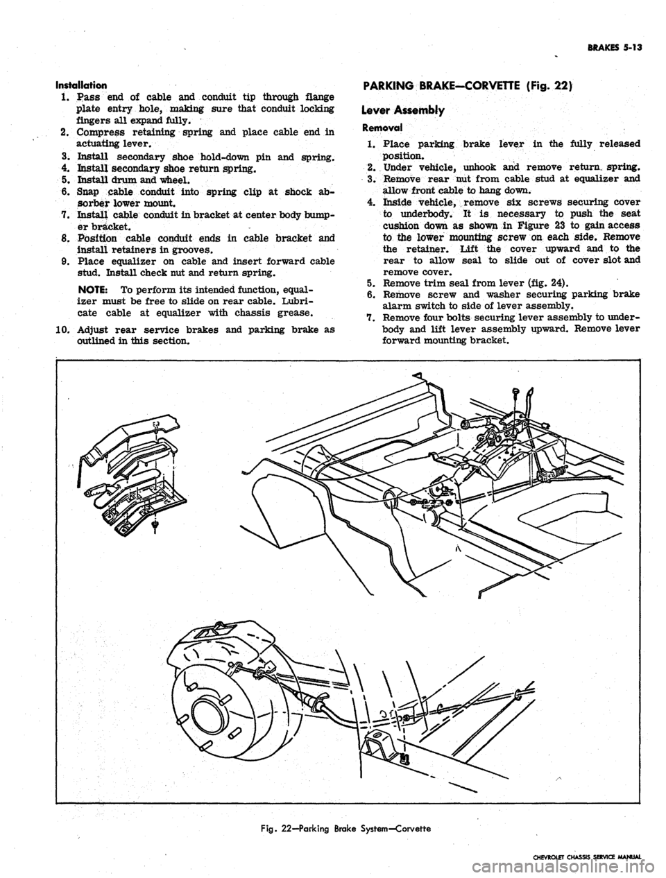
1.
Place parking brake lever in the fully released
position.
2.
Under vehicle, unhook and remove return, spring.
3.
Remove rear nut from cable stud at equalizer and
allow front cable to hang down.
4.
Inside vehicle, remove six screws securing cover
to underbody. It is necessary to push the seat
cushion down as shown in Figure 23 to gain access
to the lower mounting screw on each side. Remove
the retainer. Lift the cover upward and to the
rear to allow seal to slide out of cover slot and
remove cover.
5. Remove trim seal from lever (fig. 24).
6. Remove screw and washer securing parking brake
alarm switch to side of lever assembly.
7. Remove four bolts securing lever assembly to under-
body and lift lever assembly upward. Remove lever
forward mounting bracket.
Fig.
22—Parking Brake System—Corvette
CHEVROLET CHASSIS SERVICE MANUAL
Page 247 of 659
BRAKES 5-14
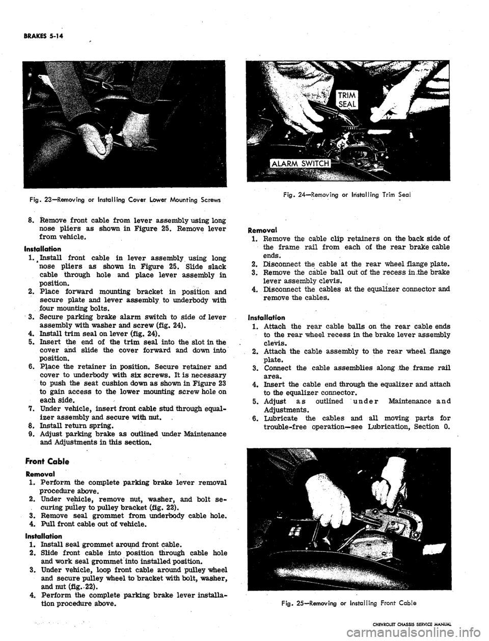
Fig.
23—Removing or Installing Cover Lower Mounting Screws
Fig.
24—Removing or Installing Trim Seal
8. Remove front cable from lever assembly using long
nose pliers as shown in Figure 25. Remove lever
from vehicle.
Installation
1.^
Install front cable in lever assembly using long
nose pliers as shown in Figure 25. Slide slack
cable through hole and place lever assembly in
position.
2.
Place forward mounting bracket in position and
secure plate and lever assembly to underbody with
four mounting bolts.
3.
Secure parking brake alarm switch to side of lever
assembly with washer and screw (fig. 24).
4.
Install trim seal on lever (fig. 24).
5. Insert the end of the trim seal into the slot in the
cover and slide the cover forward and down into
position.
6. Place the retainer in position. Secure retainer and
cover to underbody with six screws. It is necessary
to push the seat cushion down as shown in Figure 23
to gain access to the lower mounting screw hole on
each side.
7. Under vehicle, insert front cable stud through equal-
izer assembly and secure with nut.
8. Install return spring.
9. Adjust parking brake as outlined under Maintenance
and Adjustments in this section.
Front Cable
Removal
1.
Perform the complete parking brake lever removal
procedure above.
2.
Under vehicle, remove nut, washer, and bolt se-
. curing pulley to pulley bracket (fig. 22).
3.
Remove seal grommet from underbody cable hole.
4.
Pull front cable out of vehicle.
Installation
1.
Install seal grommet around front cable.
2.
Slide front cable into position through cable hole
and work seal grommet into installed position.
3.
Under vehicle, loop front cable around pulley wheel
and secure pulley wheel to bracket with bolt, washer,
and nut (fig..22).
4.
Perform the complete parking brake lever installa-
tion procedure above.
Removal
1.
Remove the cable clip retainers on the back side of
the frame rail from each of the rear brake cable
ends.
2.
Disconnect the cable at the rear wheel flange plate.
3.
Remove the cable ball out of the recess in .the brake
lever assembly clevis.
4.
Disconnect the cables at the equalizer connector and
remove the cables.
Installation
1.
Attach the rear cable balls on the rear cable ends
to the rear wheel recess in the brake lever assembly
clevis.
2.
Attach the cable assembly to the rear wheel flange
plate.
3.
Connect the cable assemblies along the frame rail
area.
4.
Insert the cable end through the equalizer and attach
to the equalizer connector.
5. Adjust as outlined under Maintenance and
Adjustments.
6. Lubricate the cables and all moving parts for
trouble-free operation—see Lubrication, Section 0.
Fig.
25—Removing or Installing Front Cable
CHEVROLET CHASSIS SERVICE MANUAL
Page 249 of 659
BRAKES 5-16
6Y. Adjust clutch pedal travel as outlined in
Section 7.
SHOES AND LININGS
Organic Linings
NOTE:
If brake drums are worn severely, it
may be necessary to retract the adjusting screw.
To gain access to the adjusting screw star
wheel, knock out the lanced area in the web of
the brake drum using a chisel or similar tool.
Release the actuator from the star wheel by
lifting with a small screw driver and back off
the star wheel with a second screw driver (press
down on the handle to retract shoes).
CAUTION: After knocking out the metal, be
sure to remove it from the inside of the drum .
and clean all metal from the brake compartment.
A new hole cover must be installed when drum
is reinstalled.
Removal
1.
Raise the vehicle and plate on jack stands.
2.
Loosen check nuts at parking brake equalizer suffi-
ciently to remove, all tension from brake cable.
3.
Remove brake drums.
NOTE:
Since there are wheel cylinder piston
stops to prevent pistons from leaving cylinders,
it is not necessary to install wheel cylinder
clamps when brake shoes are removed; however,
brake pedal must not be depressed while drums
are removed.
4.
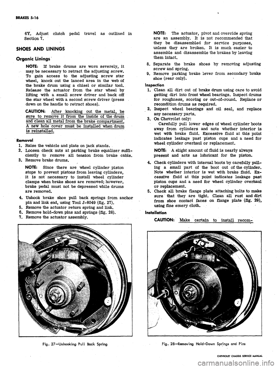
Unhook brake shoe pull back springs from anchor
pin and link end, using Tool J-8049 (fig. 27).
5. Remove the actuator return spring and link.
6. Remove hold-down pins and springs (fig. 28).
7. Remove the actuator assembly.
NOTE:
The actuator, pivot and override spring
are an assembly. It is not recommended that
they be disassembled for service purposes,
unless they are broken. It is much easier to
assemble and disassemble the brakes by leaving
them intact.
8. Separate the brake shoes by removing adjusting
screw and spring.
9. Remove parking brake lever from secondary brake
shoe (rear only).
Inspection
1.
Clean all dirt out of brake drum using care to avoid
getting dirt into front wheel bearings. Inspect drums
for roughness, scoring or out-of-round. Replace or
recondition drums as required.
2.
Inspect wheel bearings and oil seal, and replace
any necessary parts.
3.
On Chevrolet only:
Carefully pull lower edges of wheel cylinder boots
away from cylinders and note whether interior is
wet with brake fluid. Excessive fluid at this point
indicates leakage past piston cups and a need for
wheel cylinder overhaul or replacement.
NOTE:
A slight amount of fluid is nearly always
present and acts as lubricant for the piston.
4.
Check cylinders with internal boots by carefully pull-
ing a small part of the boot out of the cylinder.
Note whether interior is wet with brake fluid. Ex-
cessive fluid at this point indicates leakage past
piston cups and a need for wheel cylinder overhaul
or replacement.
5. Check all brake flange plate attaching bolts to make
sure that they are tight. Clean all rust and dirt
from shoe contact faces on flange plate (fig. 29),
using fine emery cloth.
Installation
CAUTION: Make certain to install recom-
Fig.
27-Unhooking Pull Back Spring
Fig.
28—Removing Hold-Down Springs and Pins
CHEVROLET CHASSIS SERVICE MANUAL
Page 254 of 659
BRAKES 5-21
brake fluid. Coat the primary and secondary seals
on the secondary piston with clean brake fluid. Insert
the secondary piston spring retainer into the sec-
ondary piston spring. Place the retainer and spring
down over the end of the secondary piston until the
retainer locates inside of the lips of the primary
cup.
10.
Hold the master cylinder with the open end of the
bore down. Push the secondary piston into the bore
until the spring seats against the closed end of the
bore.
11.
Position the master cylinder in a vise with the
open end of the bore up. Coat the primary and
secondary seal on the primary piston with clean
brake fluid. Push the primary piston assembly,
spring end first, into the bore of the master cylinder*
Hold the piston down and snap the lock ring into
position in the small groove in the I.D. of the bore.
12.
Push the primary piston down to move the secondary
piston forward far enough to clear the stop screw
hole in the bottom of the front fluid reservoir. Install
the stop screw.
13.
Install reservoir diaphragm in the reservoir cover
and install the cover on the main cylinder. Push
bail wire into position to secure the reservoir cover.
Installation
1.
Assemble the push rod through the push rod retainer,
if it has been disassembled.
2.
Push the retainer over the end of the main cylinder.
Assemble new boot over push rod and press it down
over the push rod retainer. Slide new mounting
gasket into position.
3.
Secure .the main cylinder to the firewall with mount-
ing bolts.
4.
Connect the push rod clevis to the brake pedal with
pin and retainer.
5. Connect the brake lines to the main cylinder.
6. Fill the main cylinder reservoirs to the levels
shown in Figure 8. Bleed the brake system as out-
lined in this section.
7. K necessary, adjust the brake pedal free play as
outlined in this section.
WHEEL CYLINDER (Fig. 33)
The wheel cylinder boots should be removed from a
cylinder body only when they are visibly damaged or
leaking fluid. Wheel cylinders having torn, cut, or heat-
cracked boots should be completely overhauled.
Removal
1.
Raise vehicle and place on jack stands.
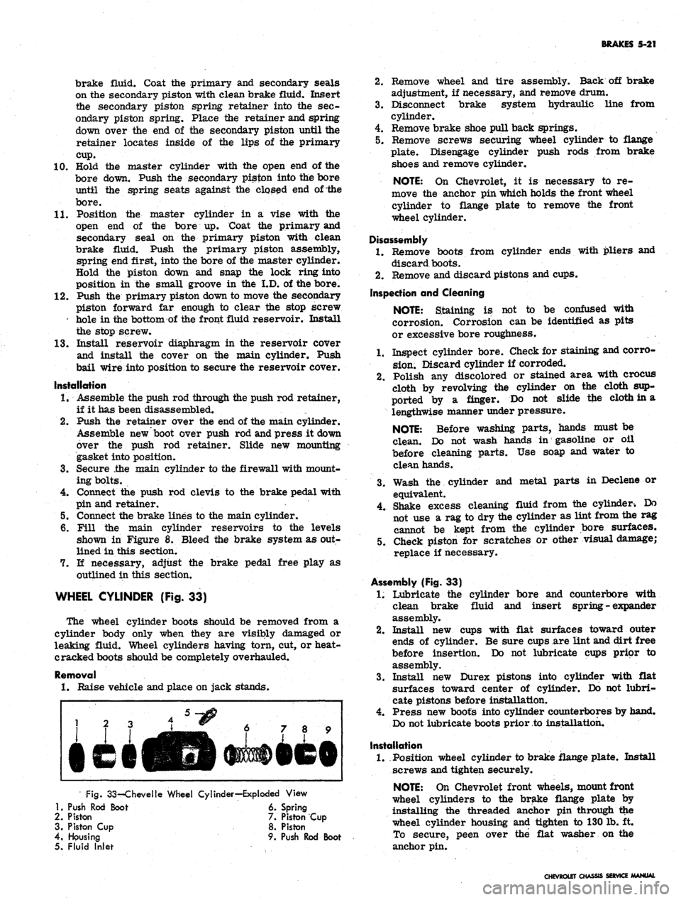
Fig.
33-Chevelle Wheel Cylinder—Exploded View
1.
Push Rod Boot 6. Spring
2.
Piston 7. Piston Cup
3. Piston Cup 8. Piston
4.
Housing 9. Push Rod Boot
5. Fluid Inlet
2.
Remove wheel and tire assembly. Back off brake
adjustment, if necessary, and remove drum.
3.
Disconnect brake system hydraulic line from
cylinder.
4.
Remove brake shoe pull back springs.
5. Remove screws securing wheel cylinder to flange
plate. Disengage cylinder push rods from brake
shoes and remove cylinder.
NOTE:
On Chevrolet, it is necessary to re-
move the anchor pin which holds the front wheel
cylinder to flange plate to remove the front
wheel cylinder.
Disassembly
1.
Remove boots from cylinder ends with pliers and
discard boots.
2.
Remove and discard pistons and cups.
Inspection and Cleaning
NOTE:
Staining is not to be confused with
corrosion. Corrosion can be identified as pits
or excessive bore roughness.
1.
Inspect cylinder bore. Check for staining and corro-
sion.
Discard cylinder if corroded.
2.
Polish any discolored or stained area with crocus
cloth by revolving the cylinder on the cloth sup-
ported by a finger. Do not slide tfce cloth in a
lengthwise manner under pressure.
NOTE:
Before washing parts, hands must be
clean. Do not wash hands in gasoline or oil
before cleaning parts. Use soap and water to
clean hands.
3.
Wash the cylinder and metal parts in Declene or
equivalent.
4.
Shake excess cleaning fluid from the cylinder-. Do
not use a rag to dry the cylinder as lint from the rag
cannot be kept from the cylinder bore surfaces.
5. Check piston for scratches or other visual damage;
replace if necessary.
Assembly (Fig. 33)
1.
Lubricate the cylinder bore and counterbore with
clean brake fluid and insert spring - expander
assembly.
2.
Install new cups with flat surfaces toward outer
ends of cylinder. Be sure cups are lint and dirt free
before insertion. Do not lubricate cups prior to
assembly.
3.
Install new Durex pistons into cylinder with flat
surfaces toward center of cylinder. Do not lubri-
cate pistons before installation.
4.
Press new boots into cylinder counterbores by hand.
Do not lubricate boots prior to installation.
Installation
1.
Position wheel cylinder to brake flange plate. Install
screws and tighten securely.
NOTE:
On Chevrolet front wheels, mount front
wheel cylinders to the brake flange plate by
installing the threaded anchor pin through the
wheel cylinder housing and tighten to 130 lb. ft.
To secure, peen over the flat washer on the
anchor pin.
CHEVROLET CHASSIS SERVICE MANUAL
Page 257 of 659
BRAKES
5-24
DISC BRAKES
INDEX
Page
General Description
. 5-24
Maintenance
and
Adjustments
5-24
Bleeding Hydraulic System
5-24
Parking Brake Adjustment
-
Corvette
5-24
Component Replacement
and
Repairs
5-25
Page
Brake Shoes
. . . . . 5-25
Brake Caliper
5-26
Brake Disc
5-29
Main Cylinder.
5-30
Parking Brake Shoes
-
Corvette
5-30
GENERAL DESCRIPTION
Four wheel disc brakes
are
standard equipment
on
the
1967
Corvette,
as in 1966. The
Corvette
may
also
be equipped with heavy duty disc brakes which include
new front calipers, shoes, linings,
and
rear pressure
regulator valve. This heavy duty option
is
used
in
conjunction with
a
vacuum power unit. Front wheel disc
brakes
are
installed
as
optional equipment
on
Chevrolet,
Chevelle, Camaro,
and
Chevy
II
models.
The disc brake,
(fig. 35),
consists
of a
fixed caliper,
rotating disc, splash shield,
and
mounting bracket.
The
caliper assembly contains four pistons and two shoe
and
lining assemblies with
the
lining riveted
to the
steel
shoes.
A
seal
and
dust boot
are
installed
on
each piston,
with
a
piston spring
in the
caliper cylinder bore beneath
each piston.
A
retaining pin extends through each caliper
half
and
both shoes
to
hold
the
shoes and linings
in
posi-
tion
in the
caliper.
On
Corvette heavy duty disc brakes,
two retaining cotter pins
are
used
at
each end
of the
caliper
to
secure
the
shoes
and
linings. Machined
sur-
faces within
the
caliper prevent
the
shoe
and
lining
assembly from rotating with
the
brake disc when pres-
sure
is
applied.
The disc, which
has a
series
of air
vent louvers
to
provide cooling,
is
mounted
on the
front wheel-hub.
The caliper straddles
the
disc and mounts
on a
mounting
bracket attached
to the
steering knuckle with
two
bolts.
The Corvette heavy duty option includes
a
pressure
regulator valve mounted
in the
rear brake line just
below
the
main cylinder. Chevrolet, Chevelle, Camaro,
and Chevy
n
models with disc brakes have
a
pressure
regulator valve mounted
in the
front brake line just
below
the
main cylinder. The valve controls
the
hydraulic
pressure
to the
front
or
rear brakes,
as
applicable,
resulting,
in the
correct pressure balance between
the
front
and
rear hydraulic systems. This valve guards
against premature .lock-up
of
front
or
rear wheels when
brakes
are
applied.
Maintenance, adjustment,
and
service operations which
are
not
included
in
this section
are the
same
as for
the Duo-Servo type brakes.
MAINTENANCE
AND
ADJUSTMENTS
BLEEDING HYDRAULIC SYSTEM
The operation
of
bleeding
the
disc brake hydraulic
system
is the
same
as for
Duo-Servo system outlined
in
the
front
of
this section. Note
the
exceptions below
and refer
to
bleeding procedures under Duo-Servo
brakes.
1.
When pressure bleeding equipment
is
used,
the
correct pressure setting
for
bleeding disc brakes
is 10-2.0
lbs. on
Corvette,
and 40 lbs. on all
other
models.
2.
The
front calipers contain
one
bleeder valve.
The
rear calipers
on
Corvette contain two bleeder valves
(one inboard
and one
outboard) which necessitates
the removal
of the
rear wheels
for
bleeding.
3.
Tapping
the
caliper with
a
rawhide mallet
as the
fluid
is
flowing
out may
assist
in
obtaining
a
good
bleeding
job.
4.
On
Chevrolet, Chevelle, Camaro
and
Chevy
II, the
spring loaded
end of the
pressure regulator valve
(fig.
36)
must
be
held (valve
in
open position) while
bleeding. This
is
done
by
depressing
and
holding
in
the
plunger
in the
end
of
the valve either
by
hand,
by taping,
or by
clamping.
PARKING BRAKE-CORVETTE
Adjustment
1.
Raise rear
end of
vehicle
and
place
on
jack stands.
2.
Remove rear wheels.
3/
Loosen brake cables
at the
equalizer until
the
park-
ing brake levers move freely
to the "off"
position
with slack
in the
cables.
4.
Turn
the
disc until
the
adjusting screw can
be
seen
through
the
hole
in the
disc.
5. Insert
an
adjusting tool
or
screw driver through
the
hole
in the
disc
and
tighten
the
adjusting screw
by
moving your hand away from
the
floor
on
both
the
left and right sides
(fig. 37).
6. Tighten until
the
disc will
not
move, then back
off
ten
(10)
notches.
7. Apply
the
parking brake four
(4)
notches from inside
the
car.
8. Tighten
the
brake cables
at the
equalizer
to
produce
a light drag with
the
wheels mounted.
9. Fully release
the
parking brake handle
and
rotate
the rear wheels.
No
drag should be evident with
the
handle released.
CHEVROLET CHASSIS SERVICE MANUAL
Page 261 of 659
BRAKES 5-28
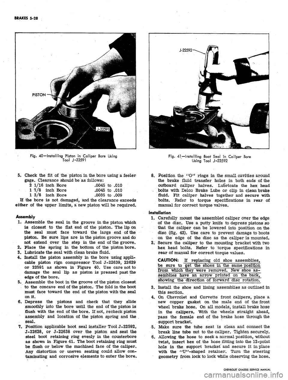
Fig.
40—Installing Piston in Caliper Bore Using
Tool J-22591
Fig.
41—Installing Boot Seal in Caliper Bore
Using Tool J-22592
5.
Check the fit of the piston in the bore using a feeler
gage.
Clearance should be as follows:
2 1/16 inch Bore .0045 to .010
1 7/8 inch Bore .0045 to .010
1 3/8 inch Bore .0035 to .009
If the bore is not damaged, and the clearance exceeds
either of the upper limits, a new piston will be required.
Assembly
1.
Assemble the seal in the groove in the piston which
is closest to the flat end of the piston. The lip on
the seal must face toward the large end of the
piston. Be sure lips are in the piston groove and do
not extend over the step in the end of the groove.
2.
Place the spring in the bottom of the piston bore.
3.
Lubricate the seal with dean brake fluid.
4.
Install the piston assembly in the bore using appli-
cable piston rign compressor Tool J-22639, 22629
or 22591 as shown in Figure 40. Use care not to
damage the seal lip as piston is pressed past the
edge of the bore. .
5.
Assemble the boot in the groove of the piston closest
to the concave end of the piston. The fold in the boot
must face toward the end of the piston with the seal
on it.
6. Depress the pistons and check that they slide
smoothly into the bore until the end of the piston is
flush with the end of the bore. If not, re check piston
assembly and location of the piston spring and the
seal.
7.
Position applicable boot seal installer Tool J-22592,
J-22628, or J-22638 over the piston and seat the
steel boot retaining ring evenly in the counterbore
as shown in Figure 41. The boot retaining ring must
be flush or below the machined face of the caliper.
Any distortion or uneven seating could allow con-
taminating and corrosive elements to enter the bore.
8. Position the t:O}> rings in the small cavities around
the brake fluid transfer holes in both ends of the
outboard caliper halves. Lubricate the hex head
. bolts with Delco Brake Lube or clip in clean brake
fluid. Fit caliper halves together and secure with
bolts.
Refer to torque specifications in rear of
manual for correct torque valves.
Installation
1.
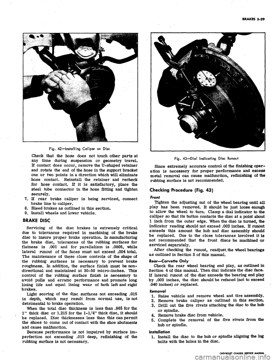
Carefully mount the assembled caliper over the edge
of the disc. Use a putty knife to depress pistons so
that the caliper can be lowered into position on the
disc (fig. 42). Use care to prevent damage to boots
• on the edge of the disc as the caliper is mounted.
2.
Secure the caliper to the mounting bracket with two
hex head bolts. Refer to torque specifications in
rear of manual for correct torque values.
CAUTION: If replacing old shoe assemblies,
be sure to get the shoes in the same position
from which they were removed. New shoe as-
semblies have an arrow printed on the back,
showing the direction of forward disc rotation.
3.
Install the shoe and lining assemblies as outlined in
this section.
4.
On Chevrolet and Corvette front calipers, place a
new copper gasket on the male end of the front
wheel brake hose. On all models, install brake hose
in the calipers. With the wheels straight ahead,
pass the female end of the brake hose through the
support bracket.
5.
Make sure the tube seat is clean and connect the
break line tube nut to the caliper. Tighten securely.
6. Allowing the hose to seek a normal position, without
twist, insert hex of the hose fitting into the 12-point
hole in the support bracket and secure it in place
with the "V"-shaped retainer. Turn the steering
geometry from lock to lock while observing the hose.
CHEVROLET CHASSIS SERVICE MANUAL
Page 262 of 659
BRAKES 5-29
Fig.
42—Installing Caliper on Disc
Check that the hose does not touch other parts at
any time during suspension or geometry travel.
If contact does occur, remove the U-shaped retainer
and rotate the end of the hose in the support bracket
one or two points in a direction which will eliminate
hose contact. Reinstall the retainer and recheck
for hose contact. If it is satisfactory, place the
steel tube connector in the hose fitting and tighten
securely.
If rear brake caliper is being serviced, connect
brake line to caliper.
Bleed brakes as outlined in this section.
Install wheels and lower vehicle.
BRAKE DISC
Servicing of the disc brakes is extremely critical
due to tolerances required in machining of the brake
disc to insure proper brake operation. In manufacturing
the brake disc, tolerances of the rubbing surfaces for
flatness is .001 and for parallelism is .0005, while
lateral runout of the faces must not exceed .004 total.
The maintenance of these close controls of the shape of
the rubbing surfaces is necessary to prevent brake
roughness. In addition, the surface finish must be non-
directional and maintained at 30-50 micro-inches. This
control of the rubbing surface finish is necessary to
avoid pulls and erratic performance and promote long
lining life and equal lining wear of both left and right
brakes.
tight scoring of the disc surfaces not exceeding .015
in depth, which may result from normal use, is not
detrimental to brake operation.
When the total disc thickness is less than .965 for the
1"
thick disc or 1.215 for the 1-1/4" thick disc, it should
be replaced. Disc thicknesses less than this can permit
the shoes to come out of contact with the shoe abutments
and cause malfunction.
Because performance is not impaired by surface im-
perfection not exceeding .015 deep, refinishing of the
rubbing surface is not necessary.
Fig.
43—Dial Indicating Disc Runout
Since extremely accurate control of the finishing oper-
ation is necessary for proper performance and excess
metal removal can cause malfunction, refinishing of the
rubbing surface is not recommended.
Checking Procedure (Fig. 43)
Front
Tighten the adjusting nut of the wheel bearing until all
play has been removed. It should be just loose enough
to allow the wheel to turn. Clamp a dial indicator to the
caliper so that its button contacts the disc at a point about
1 inch from the outer edge. When the disc is turned, the
indicator reading should not exceed .002 inches. If runout
exceeds this amount the hub and disc assembly should
be replaced. Due to the close tolerances involved it is
not recommended that the front discs be machined or
serviced separately.
After checking the runout, readjust, the wheel bearings
as outlined in Section 3 of this manual.
Rear—Corvette Only
Check the rear wheel bearing end play, as outlined in
Section 4 of this manual. Then dial indicate the disc face.
If lateral runout of the disc exceeds the bearing end play
by .003 inches, the disc should be refaced (not to exceed
.040 inches) or replaced.
Removal
1.
Raise vehicle and remove wheel and tire assembly.
/ 2. Remove brake caliper as outlined in this section.
3.
Drill out the five rivets attaching the disc to the hub
or spindle.
4.
Remove brake disc from vehicle.
5. Complete the removal of the five rivets from the
hub or spindle.
Installation
1.
Install the disc to the hub or spindle aligning the lug
bolts with the holes in the disc.
CHEVROLET CHASSIS SERVICE MANUAL
Page 264 of 659
BRAKES
5-31
POWER BRAKES
INDEX
General Description 5-31
Maintenance
and"
Adjustments 5-31
Inspection . ... 5_31
Lubrication 5-31
Bleeding Instructions . . . 5.31
Air Cleaner Service . . . , 5.31
Page
Component Replacement 5-31
Power Brake Cylinder ......* 5-31
Removal . . 5-31
Disassembly and Assembly See Overhaul Manual
Installation . . . . 5-31
GENERAL DESCRIPTION
The Power Brake Unit is a self-contained hydraulic
and vacuum unit, utilizing manifold vacuum and atmos-
phere pressure for its power.
This unit permits the use of a low brake pedal as well
as less pedal effort than is required with the conventional
(nonpower) hydraulic brake system. Only two external
line connections are necessary -
one
a vacuum connection
from manifold to check valve located on front shell; the
other, a hydraulic connection from the main cylinder
outlet directly into the hydraulic system. The unit is
mounted on the engine side of the fire wall and directly
connected to the brake pedal.
MAINTENANCE AND ADJUSTMENTS
INSPECTIONS
1.
Check vacuum line and vacuum line connections as
well as vacuum check valve in front shell of power
unit for possible vacuum loss.
2.
Inspect all hydraulic lines and connections at the
wheel cylinders and main cylinder for possible
hydraulic leaks.
3.
Check brake assemblies for scored drums, grease
or brake fluid on linings, worn or glazed linings,
and make necessary adjustments.
4.
Check brake fluid level in the hydraulic reser-
voirs.
The reservoirs should be filled to the levels
shown in Figure 8.
5. Check for loose mounting bolts at main cylinder and
at power section.
6. Check air cleaner filter in power piston extension
and replace filter if necessary.
7. Check brake pedal for binding and misalignment
between pedal
-and
push rod.
LUBRICATION
The power brake unit is lubricated at assembly and
needs no further lubrication other than maintaining
normal reservoir fluid level. The reservoir should be
filled as described in this section.
BLEEDING INSTRUCTIONS
The power system may be bled manually or with a
pressure bleeder as outlined in this section. Use only
GM
Supreme 11 Brake Fluid or equivalent. Do not use the
power assist while bleeding. The engine should not be
running and the vacuum reserve should be reduced to
zero by applying the brake several times before starting
the bleeding procedure.
AIR CLEANER SERVICE
Servicing of the air cleaner is recommended and the
element replaced when restriction becomes severe
enough to affect power brake response. At any other
time, if cleaning of the filter is felt necessary, it should
be shaken free of dirt or washed in soap and water and
thoroughly dried.
COMPONENT REPLACEMENT
POWER BRAKE CYLINDER
Removal
1.
Remove vacuum hose from vacuum check valve.
2.
Disconnect hydraulic lines at main cylinder.
Disconnect push rod at brake pedal assembly.
Remove nuts and lock washers securing power unit
to fire wall, and remove power unit from engine
compartment.
3.
4.
NOTE:
Chevy
to fire wall.
has a three stud attachment
Repair procedures for the power cylinder are outlined
in the Brake Section of the Overhaul Manual-for service
of the main cylinder refer to applicable portion of
"Standard Brakes" in this manual.
Installation
1.
Mount the power brake assembly in place and install
the attaching nuts and lock washers.
2.
Attach vacuum line to check valve.
3.
Secure hydraulic lines to main cylinder.
4.
Attach push rod to brake pedal assembly, and check
operation of stop light.
5. Bleed brakes as outlined in this section.
CAUTION: After replacing the unit on the vehi-
cle,
start the engine and allow vacuum to build
up before applying the brake.
CHEVROLET CHASSIS SERVICE
Page 278 of 659
ENGINE 6-13
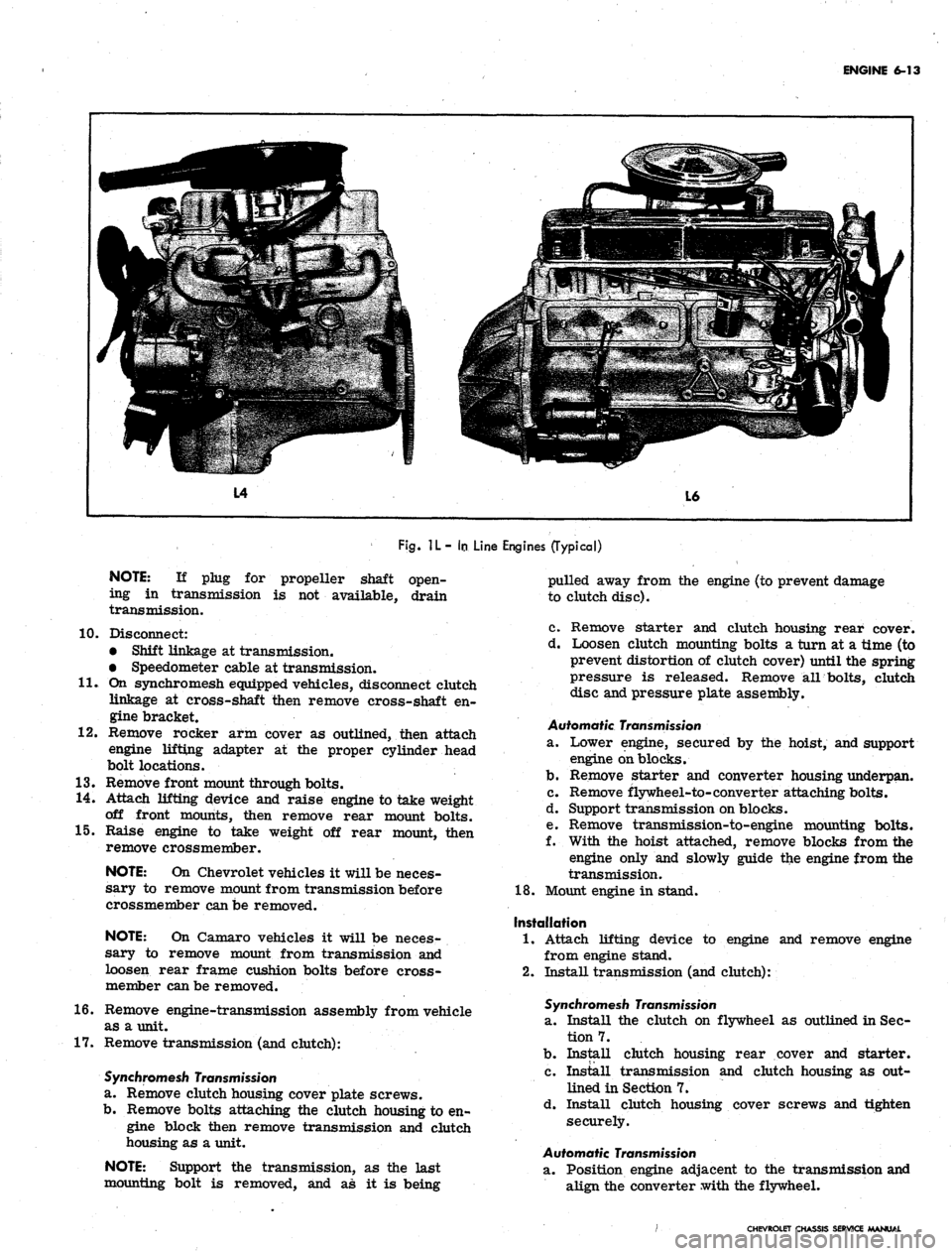
Fig.
1L- In
Line Engines (Typical)
NOTE:
If plug for propeller shaft open-
ing in transmission is not available, drain
transmission.
10.
11.
12.
Disconnect:
• Shift linkage at transmission.
• Speedometer cable at transmission.
On synchromesh equipped vehicles, disconnect clutch
linkage at cross-shaft then remove cross-shaft en-
gine bracket.
Remove rocker arm cover as outlined, then attach
engine lifting adapter at the proper cylinder head
bolt locations.
13.
Remove front mount through bolts.
14.
Attach lifting device and raise engine to take weight
off front mounts, then remove rear mount bolts.
15.
Raise engine to take weight off rear mount, then
remove crossmember.
NOTE:
On Chevrolet vehicles it will be neces-
sary to remove mount from transmission before
crossmember can be removed.
NOTE:
On Camaro vehicles it will be neces-
sary to remove mount from transmission and
loosen rear frame cushion bolts before cross-
member can be removed.
16.
Remove engine-transmission assembly from vehicle
as a unit.
17.
Remove transmission (and clutch):
Synchromesh Transmission
a. Remove clutch housing cover plate screws.
b.
Remove bolts attaching the clutch housing to en-
gine block then remove transmission and clutch
housing as a unit.
NOTE:
Support the transmission, as the last
mounting bolt is removed, and as it is being
pulled away from the engine (to prevent damage
to clutch disc).
c. Remove starter and clutch housing rear cover.
d. Loosen clutch mounting bolts a turn at a time (to
prevent distortion of clutch cover) until the spring
pressure is released. Remove all bolts, clutch
disc and pressure plate assembly.
Automatic Transmission
SL.
Lower engine, secured by the hoist, and support
engine on blocks.
b.
Remove starter and converter housing underpan.
c. Remove flywheel-to-converter attaching bolts.
d. Support transmission on blocks.
e. Remove transmission-to-engine mounting bolts.
f. With the hoist attached, remove blocks from the
engine only and slowly guide the engine from the
transmission.
18.
Mount engine in stand.
Installation
1.
Attach lifting device to engine and remove engine
from engine stand.
2.
Install transmission (and clutch):
Synchromesh Transmission
a. Install the clutch on flywheel as outlined in Sec-
tion 7.
b.
Install clutch housing rear cover and starter.
c. Install transmission and clutch housing as out-
lined in Section 7.
d. Install clutch housing cover screws and tighten
securely.
Automatic Transmission
a. Position engine adjacent to the transmission and
align the converter with the flywheel.
CHEVROLET CHASSIS SERVICE MANUAL
Page 279 of 659
ENGINE 6-14
b.
Bolt transmission to engine, then raise engine and
transmission assembly and install flywheel to
converter attaching bolts.
c. Install converter
housing*
underpan and starter.
3.
Tilt and lower engine and transmission assembly into
the chassis as a unit, guiding engine to align front
mounts with frame supports.
4.
Install front mount through bolts and torque to
specifications.
5.
Raise engine enough to install rear crossmember,
then install crossmember, install rear mount, lower
engine and torque bolts to specifications.
6. Remove lifting device and lifting adapter then install
rocker arm cover as outlined.
7.
On synchromesh equipped vehicles, install clutch
cross shaft engine bracket, then adjust and connect
clutch as outlined in Section 7.
8. Connect:
• Speedometer cable.
• Shift linkage at transmission.
9; Install propeller shaft.
10.
Remove jack stands and lower vehicle.
11.
Connect:
Power steering pump lines (if disconnected).
Vacuum line to power brake unit (if disconnected).
Fuel line at fuel pump.
Exhaust pipe at manifold flange.
Accelerator linkage at manifold bellcrank.
12.
Connect wires at:
Coil
Oil pressure switch
Temperature switch
Delcotron
Starter solenoid
13.
Install pulley, fan blade and fan belt as outlined in
Section 6K.
14.
Install radiator and shroud as outlined in Section 13.
15.
Install and adjust hood as outlined in Section 11.
16.
Connect battery cables.
17.
Fill with coolant, engine oil and transmission oil,
then start engine and check for leaks.
18.
Perform necessary adjustments and install air
cleaner.
MANIFOLD ASSEMBLY
Removal
1.
Remove air cleaner.
2.
Disconnect both throttle rods at bellcrank and re-
move throttle return spring.
3.
Disconnect fuel and vacuum lines at carburetor.
Disconnect choke cable on \A engines.
4.
Disconnect crankcase ventilation hose at rocker arm
cover.
5.
Disconnect exhaust pipe at manifold flange and dis-
card packing.
6. Remove manifold attaching bolts and clamps then
remove manifold assembly and discard gaskets.
7.
Check for cracks in manifold castings.
8. If necessary to replace either intake or exhaust
manifolds, separate them by removing one bolt and
two nuts at center of assembly. Reassemble mani-
folds using a new gasket. Tighten finger tight and
torque to specifications after assembly to cylinder
head. Transfer all necessary parts.
Installation
1.
Clean gasket surfaces on cylinder head and
manifolds*
2.
Position new gasket over manifold end studs on head
and carefully install the manifold in position making
sure the gaskets are in place.
3.
Install bolts and clamps while holding manifold in
place with hand.
4.
Torque bolts to specifications.
NOTE: On L6 engines center bolt and end bolt
torque differ.
5.
Connect exhaust pipe to manifold using a new
packing.
6. Connect crankcase ventilation hose at rocker arm
cover.
7.
Connect fuel and vacuum lines at carburetor.
8. On L4 engines connect choke cable and adjust as out-
lines in Section 6M.
9. Connect throttle rods at bellcrank and install throttle
return spring.
10.
Install air cleaner, start engine, check for leaks and
adjust carburetor idle speed and mixture.
ROCKER ARM COVER
Removal
1.
Disconnect crankcase ventilation hose(s) at rocker
arm cover.
2.
Remove air cleaner.
3.
Disconnect temperature wire from rocker arm cover
clips.
4.
Remove rocker arm cover. '
CAUTION: Do Not pry rocker arm cover loose
Gaskets adhering to cylinder head and rocker
arm cover may be sheared by bumping end of
rocker arm cover rearward with palm of hand or
a rubber mallet.
Installation
1.
Clean gasket surfaces on cylinder head and rocker
arm cover with degreaser then, using anew gasket,
install rocker arm cover and torque bolts to
specifications.
2.
Connect temperature wire at rocker arm cover clips.
3.
Install air cleaner.
4.
Connect crankcase ventilation hoses.
VALVE MECHANISM
Removal
1.
Remove rocker arm cover as outlined.
2.
Remove rocker arm nuts, rocker arm
balls,
rocker
arms and push rods.
NOTE:
Place rocker arms, rocker arm balls
and push rods in a rack so they may be rein-
stalled in the same location.
Installation and Adjustment
NOTE:
Whenever new rocker arms and/or
rocker arm balls are being installed, coat bear-
ing surfaces of rocker arms and rocker arm
balls with Molykote or its equivalent.
1.
Install push rods,
socket.
Be sure push rods seat in lifter
CHEVROLET CHASSIS SERVICE MANUAL