service indicator CHEVROLET CAMARO 1967 1.G Chassis Workshop Manual
[x] Cancel search | Manufacturer: CHEVROLET, Model Year: 1967, Model line: CAMARO, Model: CHEVROLET CAMARO 1967 1.GPages: 659, PDF Size: 114.24 MB
Page 196 of 659
REAR SUSPENSION AND DRIVE LINE 4-6
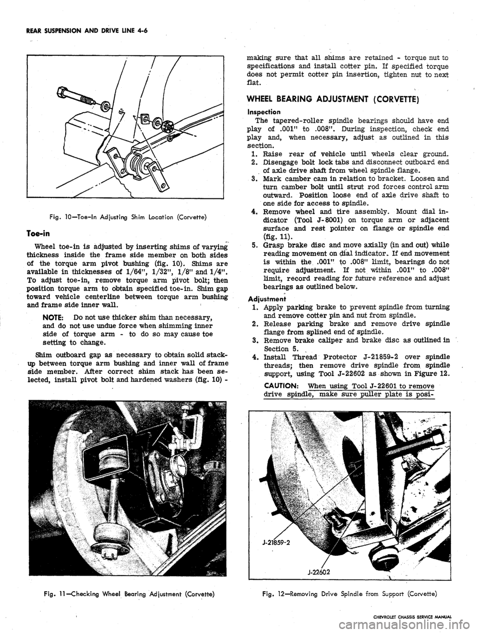
Fig.
10—Toe-in Adjusting Shim Location (Corvette)
Toe-in
Wheel toe-in is adjusted by inserting shims of varying
thickness inside the frame side member on both sides
of the torque arm pivot bushing (fig. 10). Shims are
available in thicknesses of
1/64",
1/32",
1/8" and 1/4".
To adjust toe-in, remove torque arm pivot bolt; then
position torque arm to obtain specified toe-in. Shim gap
toward vehicle centerline between torque arm bushing
and frame side inner wall.
NOTE: Do not use thicker shim than necessary,
and do not use undue force when shimming inner
side of torque arm - to do so may cause toe
setting to change.
Shim outboard gap as necessary to obtain solid stack-
up between torque arm bushing and inner wall of frame
side member. After correct shim stack has been se-
lected, install pivot bolt and hardened washers (fig. 10) -
making sure that all shims are retained - torque nut to
specifications and install cotter pin. If specified torque
does not permit cotter pin insertion, tighten nut to next
flat.
WHEEL BEARING ADJUSTMENT (CORVETTE)
inspection
The tapered-roller spindle bearings should have end
play of .001" to
.008".
During inspection, check end
play and, when necessary, adjust as outlined in this
section.
1.
Raise rear of vehicle until wheels clear ground.
2.
Disengage bolt lock tabs and disconnect outboard end
of axle drive shaft from wheel spindle flange.
3.
Mark camber cam in relation to bracket. Loosen and
turn camber bolt until strut rod forces control arm
outward. Position loose end of axle drive shaft to
one side for access to spindle.
4.
Remove wheel and tire assembly. Mount dial in-
dicator (Tool J-8001) on torque arm or adjacent
surface and rest pointer on flange or spindle end
(fig. H).
5.
Grasp brake disc and move axially (in and out) while
reading movement on dial indicator. If end movement
is within the .001" to .008" limit, bearings do not
require adjustment. If not within .001" to .008"
limit, record reading for future reference and adjust
bearings as outlined below.
Adjustment
1.
Apply parking brake to prevent spindle from turning
and remove cotter pin and nut from spindle.
2.
Release parking brake and remove drive spindle
flange from splined end of spindle.
3.
Remove brake caliper and brake disc as outlined in
Section 5.
4.
Install Thread Protector J-21859-2 over spindle
threads; then remove drive spindle from spindle
support, using Tool J-22602 as shown in Figure 12.
CAUTION: When using Tool J-22601 to remove
drive spindle, make sure puller plate is posi-
Fig.
11—Checking Wheel Bearing Adjustment (Corvette)
Fig. 12—Removing Drive Spindle from Support (Corvette)
CHEVROLET CHASSIS SERVICE MANUAL
Page 197 of 659
REAR SUSPENSION AND DRIVE LINE 4-7
tioned vertically in the torque arm before ap-
plying pressure to the puller screw.
5.
Remove shim and bearing spacer from spindle
support.
6. Note size of shim used. If dial indicator reading
was more than
.008",
select a shim thinner by the
amount needed to bring end play within limits. If
dial indicator reading was less than
.001",
select a
shim thicker by the amount needed to bring end play
within limits.
NOTE: Shims are available in thicknesses from
.097"
to .148" in increments of
.003".
EXAMPLE: Bearing end play reading obtained
on dial indicator was
.011",
.003" over limit.
Bearing shim removed from spindle measures
.145".
New shim installed measures .139", .006"
smaller. End play is now decreased by .006" and
is
.005",
which is within the .001" to .008" limit.
7.
After determining shim thickness, install bearing
spacer and shim on spindle. Position spindle in
spindle support.
8. Press inner bearing race and roller assembly on
spindle as follows.
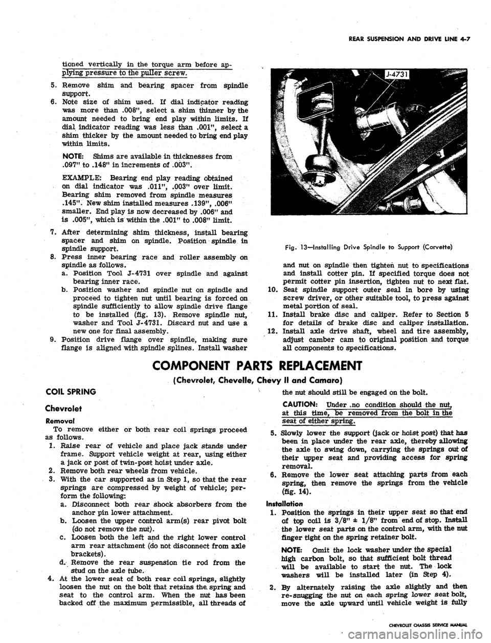
a. Position Tool J-4731 over spindle and against
bearing inner race.
b.
Position washer and spindle nut on spindle and
proceed to tighten nut until bearing is forced on
spindle sufficiently to allow spindle drive flange
to be installed (fig. 13). Remove spindle nut,
washer and Tool
J-4731.
Discard nut and use a
new one for final assembly.
9. Position drive flange over spindle, making sure
flange is aligned with spindle splines. Install washer
Fig.
13—Installing Drive Spindle to Support (Corvette)
and nut on spindle then tighten nut to specifications
and install cotter pin. If specified torque does not
permit cotter pin insertion, tighten nut to next flat.
10.
Seat spindle support outer seal in bore by using
screw driver, or other suitable tool, to press against
metal portion of seal.
11.
Install brake disc and caliper. Refer to Section 5
for details of brake disc and caliper installation.
12.
Install axle drive shaft, wheel and tire assembly,
adjust camber cam to original position and torque
all components to specifications.
COMPONENT PARTS REPLACEMENT
(Chevrolet, Chevelle, Chevy II and Camaro)
COIL SPRING
Chevrolet
Removal
To remove either or both rear coil springs proceed
as follows.
1.
Raise rear of vehicle and place jack stands under
frame. Support vehicle weight at rear, using either
a jack or post of twin-post hoist under axle.
2.
Remove both rear wheels from vehicle.
3.
With the car supported as in Step 1, so that the rear
springs are compressed by weight of vehicle; per-
form the following:
a. Disconnect both rear shock absorbers from the
anchor pin lower attachment.
b.
Loosen the upper control arm(s) rear pivot bolt
(do not remove the nut).
C. Loosen both the left and the right lower control
arm rear attachment (do not disconnect from axle
brackets).
d. Remove the rear suspension tie rod from the
stud on the axle tube.
4.
At the lower seat of both rear coil springs, slightly
loosen the nut on the bolt that retains the spring and
seat to the control arm. When the nut has been
backed off the maximum permissible, all threads of
the nut should still be engaged on the bolt.
CAUTION: Under ,no condition should the nut,
at this time, be removed from the bolt in the
seat of either spring.
5.
Slowly lower the support (jack or hoist post) that has
been in place under the rear axle, thereby allowing
the axle to swing down, carrying the springs out of
their upper seat and providing access for spring
removal.
6. Remove the lower seat attaching parts from each
spring, then remove the springs from the vehicle
(fig. 14).
Installation
1.
Position the springs in their upper seat so that end
of top coil is 3/8" ± 1/8" from end of stop. Install
the lower seat parts on the control arm, with the nut
finger tight on the spring retainer bolt.
NOTE: Omit the lock washer under the special
high carbon bolt, so that sufficient bolt thread
will be available to start the nut. The lock
washers will be installed later (in Step 4).
2.
By alternately raising the axle slightly and then
re-snugging the nut on each spring lower seat bolt,
move the axle upward until vehicle weight is fully
CHEVROLET CHASSIS SERVICE MANUAL
Page 233 of 659
REAR SUSPENSION AND DRIVE LINE 4-43
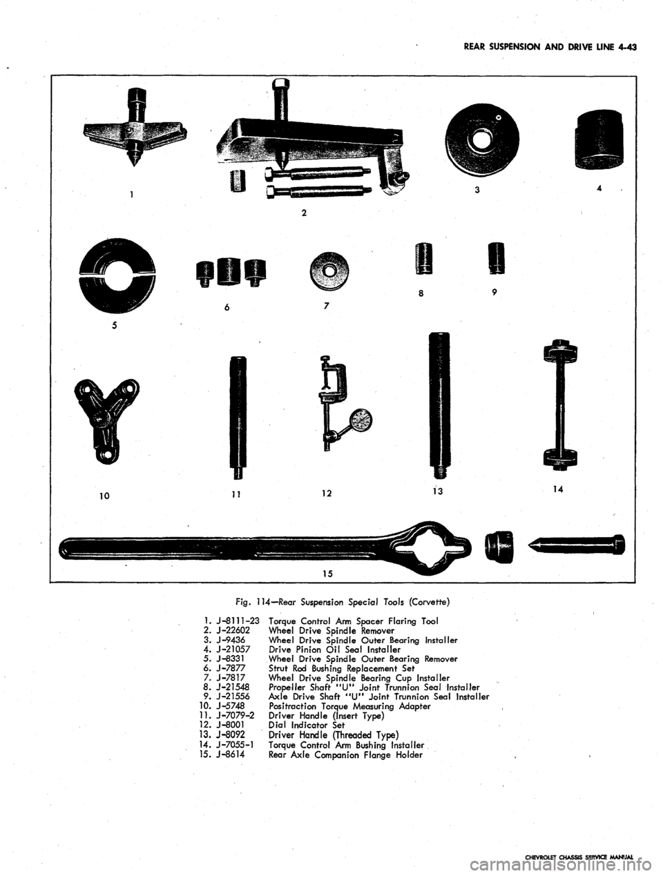
Fig.
114—Rear Suspension Special Tools (Corvette)
1.
J-8111-23 Torque Control Arm Spacer Flaring Tool
2.
J-22602 Wheel Drive Spindle Remover
3.
J-9436 Wheel Drive Spindle Outer Bearing Installer
4.
J-21057 Drive Pinion Oil Seal Installer
5. J-8331 Wheel Drive Spindle Outer Bearing Remover
6.
J-7877 Strut Rod Bushing Replacement Sef
7. J-7817 Wheel Drive Spindle Bearing Cup Installer
8.
J-21548 Propeller Shaft "U" Joint Trunnion Seal Installer
9. J-21556 Axle Drive Shaft "U" Joint Trunnion Sea! Installer
10.
J-5748 Positraction Torque Measuring Adapter
11.
J-7079-2 Driver Handle (Insert Type)
12.
J-8001 Dial Indicator Set
13.
J-8092 Driver Handle (Threaded Type)
14.
J-7055-1 Torque Control Arm Bushing Installer
15.
J-8614 Rear Axle Companion Flange Holder
CHEVROLET CHASSIS SERVICE MANUAL
Page 234 of 659
BRAKES
SECTION 5
CONTENTS OF THIS SECTION
Duo Servo Brakes
Disc Brakes
Page
5-1 Power Brakes
5-24 Special Tools
Page
5-31
5-32
DUO-SERVO BRAKES
INDEX
Page
General Description 5-1
Maintenance and Adjustments 5-3
Hydraulic Brake Fluid .. . 5-3
Bleeding Hydraulic System 5-3
Pressure Bleeding 5-3
Manual Bleeding 5_4
Push Rod to Main Cylinder Clearance 5-5
Hydraulic Brake Lines 5-5
Hydraulic Brake Hose 5-5
Hydraulic Brake Tubing 5-6
Brake Adjustment. .................... 5-7
Service Brake 5-7
Parking Brake 5-8
Component Replacement and Repairs 5-9
Parking Brake - Chevrolet, Chevelle and
Camaro 5^9
Pedal Assembly 5-9
Front Cable ,. . . 5-9
Center Cable 5-9
Rear Cables. . 5-9
Parking Brake - Chevy n 5-9
Lever Assembly 5-9
Idler Lever 5-11
Front Cable 5-11
Rear Cable . . ; 5-12
Parking Brake - Corvette 5-13
Lever Assembly . . . . 5-13
Front Cable 5-14
Rear Cable . . 5-14
Brake Pedal 5-15
Shoes and Linings 5-16
Organic 5-16
Metallic 5-17
Main Cylinder 5-18
Wheel Cylinders 5-21
Anchor Pin 5-22
Front Wheel 5-22
Rear Wheel 5-22
Brake Drums • 5-22
Brake Pipe Distribution and Switch Assembly . . . . . 5-23
Camaro Pressure Regulator Valve 5-23
GENERAL DESCRIPTION
All 1967 models are equipped with a new split brake
system as a safety feature. If a wheel cylinder or brake
line should fail at either the front end or rear end of
the vehicle, the operator can still bring the vehicle to
a controlled stop. The system is designed with separate
hydraulic systems for the front and rear brake using
a dual master cylinder (fig. 1). The design of the master
cylinder is similar to that used on the 1966 Corvette
in that it has two entirely separate reservoirs and outlets
in a common body casting. The front reservoir and outlet
is connected to the front wheel brakes, and the rear
reservoir and outlet is connected to the rear wheel
brakes. Two pistons within the master cylinder receive
mechanical pressure from the brake pedal push rod and
transmit it through the brake lines as hydraulic pressure
to the wheel cylinders. The filler cap is accessible from
inside the engine compartment.
A new brake pipe distribution and switch assembly
is mounted below the main cylinder. The front and rear
hydraulic brake lines are routed from the main cylinder,
through the brake pipe distribution and switch assembly,
to the front and rear brakes as shown in Figure 2. The
switch is wired electrically to the brake alarm indicator
light on the instrument panel. In the event of fluid loss
in either the front or rear brake system the indicator
on the instrument panel will illuminate red. (The indi-
cator will also' be illuminated when the parking brake is
applied.)
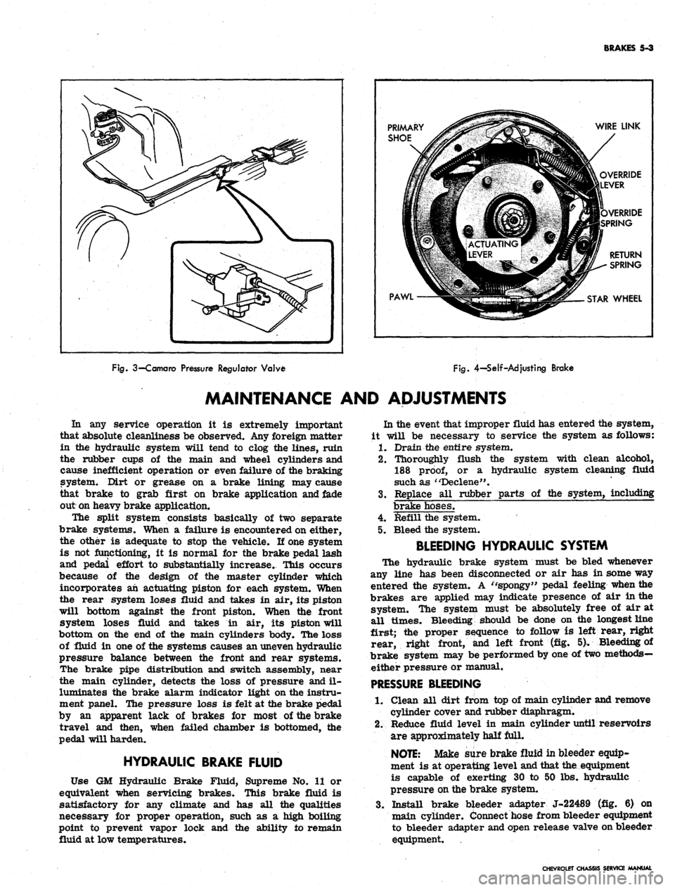
On Camaro models equipped with air conditioning, the
rear brake hydraulic line is routed through a pressure
regulator valve mounted on the left frame side rail
(fig. 3). The valve controls the hydraulic pressure to
the rear brakes resulting in the correct pressure balance
between the front and rear hydraulic systems.
The self-adjusting brakes (fig. 4), used on both front
and rear of all models, are the Duo-Servo single anchor
type which utilize the momentum of the vehicle to assist
in the brake application. The self-energizing or
self-
actuating force is applied to both brake shoes at each
wheel in both forward and reverse motion. The brake
shoe linings are bonded to the shoes.
Wheel cylinders are the double piston type permitting
even distribution of pressure to each brake shoe. To
keep out dust and moisture, both ejads of each wheel
cylinder are sealed with a rubber booC The wheel
cylinders have no adjustments.
The Chevrolet, Chevelle, and Camaro parking brakes
have a foot operated ratchet type pedal mounted to the
left of the steering column. A cable assembly connects
the pedal to an intermediate cable by means of an equal-
izer, where the adjustment for the parking brake is
incorporated. The intermediate cable attaches to the
CHEVROLET CHASSIS SERVICE MANUAL
Page 236 of 659
BRAKES
5-3
PRIMARY
SHOE
PAWL
WIRE LINK
OVERRIDE
LEVER
VERRIDE
SPRING
RETURN
SPRING
STAR
WHEEL
Fig.
3—Camaro
Pressure
Regulator
Valve
Fig.
4-Self-Adjusting
Brake
MAINTENANCE AND ADJUSTMENTS
In any service operation it is extremely important
that absolute cleanliness be observed. Any foreign matter
in the hydraulic system will tend to clog the lines, ruin
the rubber cups of the main and wheel cylinders and
cause inefficient operation or even failure of the braking
system. Dirt or grease on a brake lining may cause
that brake to grab first on brake application and fade
out on heavy brake application.
The split system consists basically of two separate
brake systems. When a failure is encountered on either,
the other is adequate to stop the vehicle. If one system
is not functioning, it is normal for the brake pedal lash
and pedal effort to substantially increase. This occurs
because of the design of the master cylinder which
incorporates ah actuating piston for each system. When
the rear system loses fluid and takes in air, its piston
will bottom against the front piston. When the front
system loses fluid and takes in air, its piston will
bottom on the end of the main cylinders body. The loss
of fluid in one of the systems causes an uneven hydraulic
pressure balance between the front and rear systems.
The brake pipe distribution and switch assembly, near
the main cylinder, detects the loss of pressure and il-
luminates the brake alarm indicator light on the instru-
ment panel. The pressure loss is felt at the brake pedal
by an apparent lack of brakes for most of the brake
travel and then, when failed chamber is bottomed, the
pedal will harden.
HYDRAULIC BRAKE FLUID
Use GM Hydraulic Brake Fluid, Supreme No. 11 or
equivalent when servicing brakes. This brake fluid is
satisfactory for any climate and has all the qualities
necessary for proper operation, such as a high boiling
point to prevent vapor lock and the ability to remain
fluid at low temperatures.
In the event that improper fluid has entered the system,
it will be necessary to service the system as follows:
1.
Drain the entire system.
2.
Thoroughly flush the system with clean alcohol,
188
proof,
or a hydraulic system cleaning fluid
such as "Declene".
3.
Replace all rubber parts of the system, including
brake hoses.
4.
Refill the system.
5. Bleed the system.
BLEEDING HYDRAULIC SYSTEM
The hydraulic brake system must be bled whenever
any line has been disconnected or air has in some way
entered the system. A ''spongy" pedal feeling when the
brakes are applied may indicate presence of air in the
system. The system must be absolutely free of air at
all times. Bleeding should be done on the longest line
first; the proper sequence to follow is left rear, right
rear, right front, and left front (fig. 5). Bleeding of
brake system may be performed by one of two methods—
either pressure or manual.
PRESSURE
BLEEDING
1.
Clean all dirt from top of main cylinder and remove
cylinder cover and rubber diaphragm.
2.
Reduce fluid level in main cylinder until reservoirs
are approximately half full.
NOTE:
Make sure brake fluid in bleeder equip-
ment is at operating level and that the. equipment
is capable of exerting 30 to 50 lbs. hydraulic
pressure on the brake system.
3.
Install brake bleeder adapter J-22489 (fig. 6) on
main cylinder. Connect hose from bleeder equipment
to bleeder adapter and open release valve on bleeder
equipment.
CHEVROLET CHASSIS SERVICE MANUAL
Page 255 of 659
BRAKES 5-22
2.
Replace ail push rods and pull back springs.
3.
Connect hose or line to wheel cylinder.
NOTE:
If replacing front wheel cylinder, con-
nect hose and inspect installation as outlined in
"Hydraulic Brake Hose Replacement".
4.
Install drum and wheel.
5. Bleed brakes as outlined in this section.
ANCHOR PIN
Front Wheel
1.
Raise front of vehicle and place on jack stands.
2.
Remove wheel and drum as outlined in this section.
3.
Remove brake shoe pull back springs, link and guide
plate.
4.
Disengage anchor pin lock and remove anchor pin by
turning counterclockwise.
5. Place new lock plate on anchor pin and pass pin
through the hole in flange plate and screw into tapped
hole in spindle support.
6. Torque pin to 130 lb. ft. and lock by peening over
washer tabs.
7. Install brake shoe guide plate, link and pull back
springs.
8. Adjust brakes, install drum and wheel as outlined
in this section. Test brake operation.
Rear Wheel
Two type anchor pins are used in production for the
rear wheels. The riveted type is not serviced and if
failure or damage should occur to either the anchor
pin or flange plate, both parts will have to be replaced
and the threaded type anchor pin used.
Threaded Type
1.
Raise rear of vehicle and place on jack stands,
2.
Remove wheel and drum as outlined in this section.
3.
Remove brake shoe pull back springs, link and guide
plate.
4.
Remove anchor pin retaining nut and washer and
remove pin from flange plate.
5. Position anchor pin to flange plate, install lock
washer and nut, and torque pin to 80 lb. ft.
6. Install brake shoe guide plate, link and pull back
springs.
7. Adjust brakes and install drum and wheel as outlined
in this section.
8. Test brake operation.
BRAKE DRUMS
Front brake drums are the demountable type; that is,
they can be removed without removing the hub. Rear
brake drums are demountable and may be removed
wihtout removing the axle shaft.
A lanced "knock out" area (fig. 34) is provided in
the web of the brake drum for servicing purposes in
the event retracting of the brake shoes is required in
order to remove the drum.
A small screw driver or hooked wire may be inserted
to disengage the automatic adjuster actuating lever so
the star wheel may be turned.
Removal
1.
Raise vehicle and place on jack stand.
2.
Remove wheel and tire assembly, back off brake
adjustment and remove drum.
Inspection and Reconditioning
Whenever brake drums are removed they should be
thoroughly cleaned and inspected for cracks, scores,
deep grooves, and out-of-round. Any of these conditions
must be corrected since they can impair the efficiency
of brake operation and also can cause premature failure
of other parts.
Smooth up any slight scores by polishing with fine
emery cloth. Heavy or extensive scoring will cause
excessive brake lining wear and it will probably be
necessary to rebore in order to true up the braking
surface.
An out-of-round drum makes accurate brake shoe
adjustment impossible and is likely to cause excessive
wear of other parts of brake mechanism due to its
eccentric action.
A drum that is more than .008" out-of-round on the
diameter is unfit for service and should be rebored.
Out-of^round, as well as taper and wear can be ac-
curately measured with an inside micrometer fitted
with proper extension rods.
If drum is to be rebored for use with standard size
brake facings which are worn very little, only enough
metal should be removed to obtain a true smooth braking
surface.
If drum has to be rebored more than .020" over the
standard diameter, it should be rebored to .060" diameter
oversize and the brake facing should be replaced with
.030"
oversize facings.
A brake drum must not be rebored more than .060"
over the maximum standard diameter, since removal
of more metal will effect, dissipation of heat and may
cause distortion of drum. Chevrolet brake facing is
not furnished larger than .030" oversize and this will
not work efficiently in drums bored more than .060"
oversize.
Brake drums may be refinished either by turning or
grinding. Best brake performance is obtained by turning
drums with a very fine feed. To insure maximum lining
life,
the refinished braking surface must be smooth and
free from chatter or tool marks, and run-out must not
exceed .005" total indicator reading.
Cleaning
New brake drums in parts stock are given a light.
coating of rust proofing oil to prevent the formation of
rust on the critical braking surfaces during the time
that the drums are in storage.
This rust proofing oil must be carefully removed
before the drum is placed in service to prevent any
of this oil from getting on the brake shoe facings, which
might cause an extreme brake grab condition.
It is recommended that a suitable volatile, non-toxic,
greaseless type solvent be used to clean the oil from the
braking surface of the new brake drums before they are
•placed in service to insure the cleanest possible surface.
Gasoline or kerosene should not be used as there is
danger that a portion of the diluated oil substance may
be left on the braking surface that may later cause
difficulty.
Installation
1.
Make brake adjustment as outlined in this section.
CHEVROLET CHASSIS SERVICE MANUAL
Page 262 of 659
BRAKES 5-29
Fig.
42—Installing Caliper on Disc
Check that the hose does not touch other parts at
any time during suspension or geometry travel.
If contact does occur, remove the U-shaped retainer
and rotate the end of the hose in the support bracket
one or two points in a direction which will eliminate
hose contact. Reinstall the retainer and recheck
for hose contact. If it is satisfactory, place the
steel tube connector in the hose fitting and tighten
securely.
If rear brake caliper is being serviced, connect
brake line to caliper.
Bleed brakes as outlined in this section.
Install wheels and lower vehicle.
BRAKE DISC
Servicing of the disc brakes is extremely critical
due to tolerances required in machining of the brake
disc to insure proper brake operation. In manufacturing
the brake disc, tolerances of the rubbing surfaces for
flatness is .001 and for parallelism is .0005, while
lateral runout of the faces must not exceed .004 total.
The maintenance of these close controls of the shape of
the rubbing surfaces is necessary to prevent brake
roughness. In addition, the surface finish must be non-
directional and maintained at 30-50 micro-inches. This
control of the rubbing surface finish is necessary to
avoid pulls and erratic performance and promote long
lining life and equal lining wear of both left and right
brakes.
tight scoring of the disc surfaces not exceeding .015
in depth, which may result from normal use, is not
detrimental to brake operation.
When the total disc thickness is less than .965 for the
1"
thick disc or 1.215 for the 1-1/4" thick disc, it should
be replaced. Disc thicknesses less than this can permit
the shoes to come out of contact with the shoe abutments
and cause malfunction.
Because performance is not impaired by surface im-
perfection not exceeding .015 deep, refinishing of the
rubbing surface is not necessary.
Fig.
43—Dial Indicating Disc Runout
Since extremely accurate control of the finishing oper-
ation is necessary for proper performance and excess
metal removal can cause malfunction, refinishing of the
rubbing surface is not recommended.
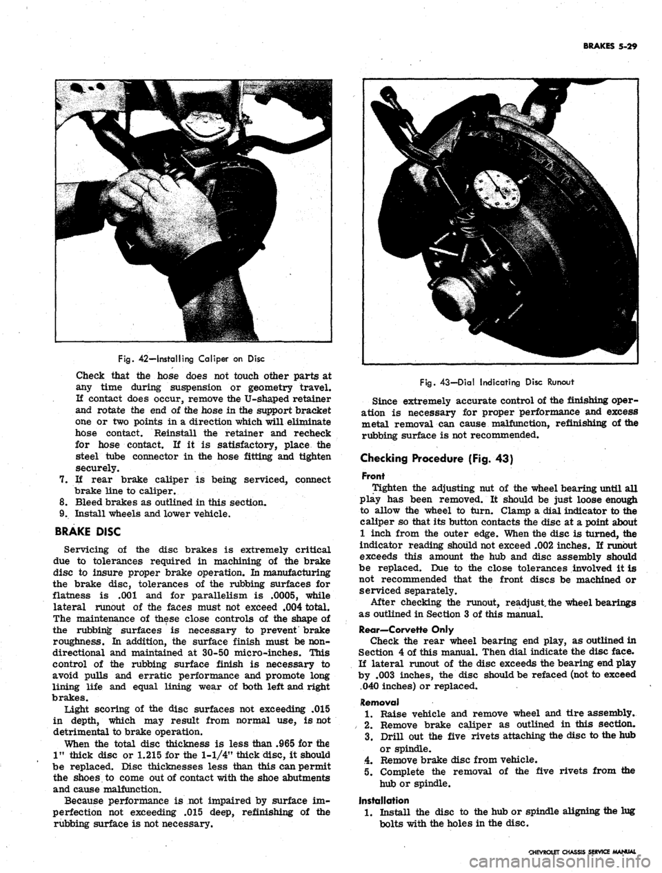
Checking Procedure (Fig. 43)
Front
Tighten the adjusting nut of the wheel bearing until all
play has been removed. It should be just loose enough
to allow the wheel to turn. Clamp a dial indicator to the
caliper so that its button contacts the disc at a point about
1 inch from the outer edge. When the disc is turned, the
indicator reading should not exceed .002 inches. If runout
exceeds this amount the hub and disc assembly should
be replaced. Due to the close tolerances involved it is
not recommended that the front discs be machined or
serviced separately.
After checking the runout, readjust, the wheel bearings
as outlined in Section 3 of this manual.
Rear—Corvette Only
Check the rear wheel bearing end play, as outlined in
Section 4 of this manual. Then dial indicate the disc face.
If lateral runout of the disc exceeds the bearing end play
by .003 inches, the disc should be refaced (not to exceed
.040 inches) or replaced.
Removal
1.
Raise vehicle and remove wheel and tire assembly.
/ 2. Remove brake caliper as outlined in this section.
3.
Drill out the five rivets attaching the disc to the hub
or spindle.
4.
Remove brake disc from vehicle.
5. Complete the removal of the five rivets from the
hub or spindle.
Installation
1.
Install the disc to the hub or spindle aligning the lug
bolts with the holes in the disc.
CHEVROLET CHASSIS SERVICE MANUAL
Page 286 of 659
ENGINE 6-21
CAUTION: Support cover
•
at sealing area.
(Tool J-971 may be used as support.)
Without Cover
Removal
1.
With crankshaft pulley and nub or torsional damper
removed, pry old seal out of cover from the front
with a large screw driver, being careful not to dam-
age the seal surface on the cover.
2.
Install new seal so that open end of seal is toward the
inside of cover and drive it into position with Tool
J-8340 (fig. 13L).
CAMSHAFT
Measuring Lobe Lift
NOTE: Procedure is similar to that used for
checking valve timing.. If improper valve
operation is indicated, measure the lift of each
push rod in consecutive order and record the
readings.
1.
Remove valve mechanism as outlined.
2.
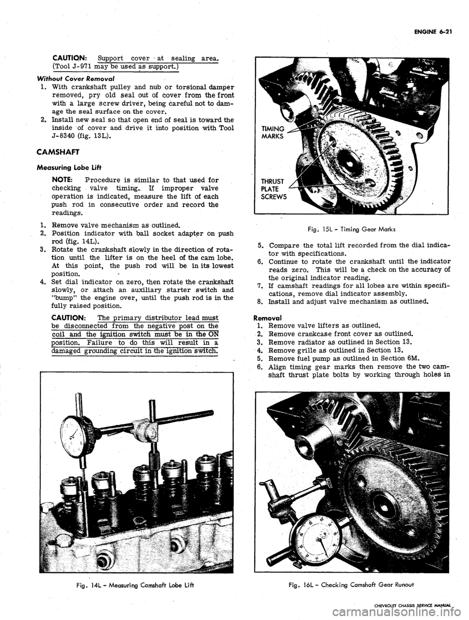
Position indicator with ball socket adapter on push
rod (fig. 14L).
3.
Rotate the crankshaft slowly in the direction of rota-
tion until the lifter is on the heel of the cam lobe.
At this point, the push rod will be in its lowest
position.
4.
Set dial indicator on zero, then rotate the crankshaft
slowly, or attach an auxiliary starter switch and
"bump" the engine over, until the push rod is in the
fully raised position.
CAUTION: The primary distributor lead must
be disconnected from the negative post on the
coil and the ignition switch must be in the ON
position. Failure to do this will result in a
damaged grounding circuit in the ignition switch.
Fig.
15L - Timing Gear Marks
5.
Compare the total lift recorded from the dial indica-
tor with specifications.
6. Continue to rotate the crankshaft until the indicator
reads zero. This will be a check on the accuracy of
the original indicator reading.
7.
If camshaft readings for all lobes are within specifi-
cations, remove dial indicator assembly.
8. Install and adjust valve mechanism as outlined.
Removal
1.
Remove valve lifters as outlined,
2.
Remove crankcase front cover as outlined.
3.
Remove radiator as outlined in Section 13.
4.
Remove grille as outlined in Section 13.
5.
Remove fuel pump as outlined in Section 6M.
6. Align timing gear marks then remove the two cam-
shaft thrust plate bolts by working through holes in
Fig.
ML - Measuring Camshaft Lobe Lift
Fig.
16L - Checking Camshaft Gear Runout
CHEVROLET CHASSIS SERVICE MANUAL
Page 287 of 659
ENGINE 6-22
the camshaft gear (fig. 15L).
7.
Remove the camshaft and gear assembly by pulling it
out through the front of the block.
NOTE: Support camshaft carefully when re-
moving so as not to damage camshaft bearings.
Installation
1.
Install the camshaft and gear assembly in the engine
block, being careful not to damage camshaft bearings
or camshaft.
2.
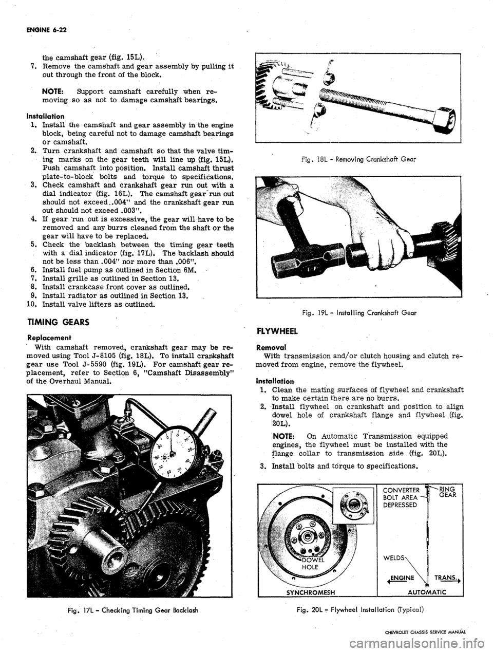
Turn crankshaft and camshaft so that the valve tim-
ing marks on the gear teeth will line up (fig. 15L).
Push camshaft into position. Install camshaft thrust
plate-to-block bolts and torque to specifications.
3.
Check camshaft and crankshaft gear run out with a
dial indicator (fig. 16L). The camshaft gear"run out
should not exceed,.004" and the crankshaft gear run
out should not exceed
.003".
4.
If gear mm out is excessive, the gear will have to be
removed and any burrs cleaned from the shaft or the
gear will have to be replaced.
5.
Check the backlash between the timing gear teeth
with a dial indicator (fig. 17L). The backlash should
not be less than .004" nor more than .006".
6. Install fuel pump as outlined in Section 6M.
7.
Install grille as outlined in Section 13.
8. Install crankcase front cover as outlined.
9. Install radiator as outlined in Section 13.
10.
Install valve lifters as outlined.
TIMING GEARS
Replacement
With camshaft removed, crankshaft gear may be re-
moved using Tool J-8105 (fig. 18L). To install crankshaft
gear use Tool J-5590 (fig. 19L). For camshaft gear re-
placement, refer to Section 6, "Camshaft Disassembly"
of the Overhaul Manual.
Fig.
18L
- Removing Crankshaft Gear
Fig.
19L- Installing Crankshaft Gear
FLYWHEEL
Removal
With transmission and/or clutch housing and clutch re-
moved from engine, remove the flywheel.
Installation
1.
Clean the mating surfaces of flywheel and crankshaft
to make certain there are no burrs.
2.
Install flywheel on crankshaft and position to align
dowel hole of crankshaft flange and flywheel (fig.
20L).
NOTE: On Automatic Transmission equipped
engines, the flywheel must be installed with the
flange collar to transmission side (fig. 20L).
3.
Install bolts and torque to specifications.
SYNCHROMESH
CONVERTER
BOLT AREA -
DEPRESSED
•RING
GEAR
TRANS.,
AUTOMATIC
Fig. 17L
—
Checking Timing Gear Backlash
Fig. 20L r Flywheel Installation (Typical)
CHEVROLET CHASSIS SERVICE MANUAL
Page 301 of 659
ENGINE 6-36
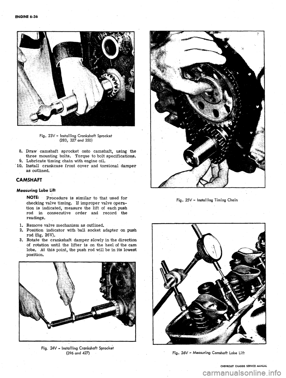
Fig.
23V - Installing Crankshaft Sprocket
(283,
327
and
350)
8* Draw camshaft sprocket onto camshaft, using the
three mounting bolts. Torque to bolt specifications.
9. Lubricate timing chain with engine oil.
10.
Install crankcase front cover and torsional damper
as outlined.
CAMSHAFT
Measuring Lobe Lift
NOTE: Procedure is similar to that used for
checking valve timing. If improper valve opera-
tion is indicated, measure the lift of each push
rod in consecutive order and record the
readings.
1.
Remove valve mechanism as outlined.
2.
Position indicator with ball socket adapter on push
rod (fig. 26V).
3.
Rotate the crankshaft damper slowly in the direction
of rotation until the lifter is on the heel of the cam
lobe.
At this point, the push rod will be in its lowest
position.
Fig.
25V- Installing Timing Chain
Fig.
24V - Installing Crankshaft Sprocket
(396 and 427)
Fig.
26V - Measuring Camshaft Lobe Lift
CHEVROLET CHASSIS SERVICE MANUAL