warning CHEVROLET CAMARO 1967 1.G Chassis Owner's Manual
[x] Cancel search | Manufacturer: CHEVROLET, Model Year: 1967, Model line: CAMARO, Model: CHEVROLET CAMARO 1967 1.GPages: 659, PDF Size: 114.24 MB
Page 552 of 659
ELECTRICAL-BODY AND CHASSIS 12-40
Fig.
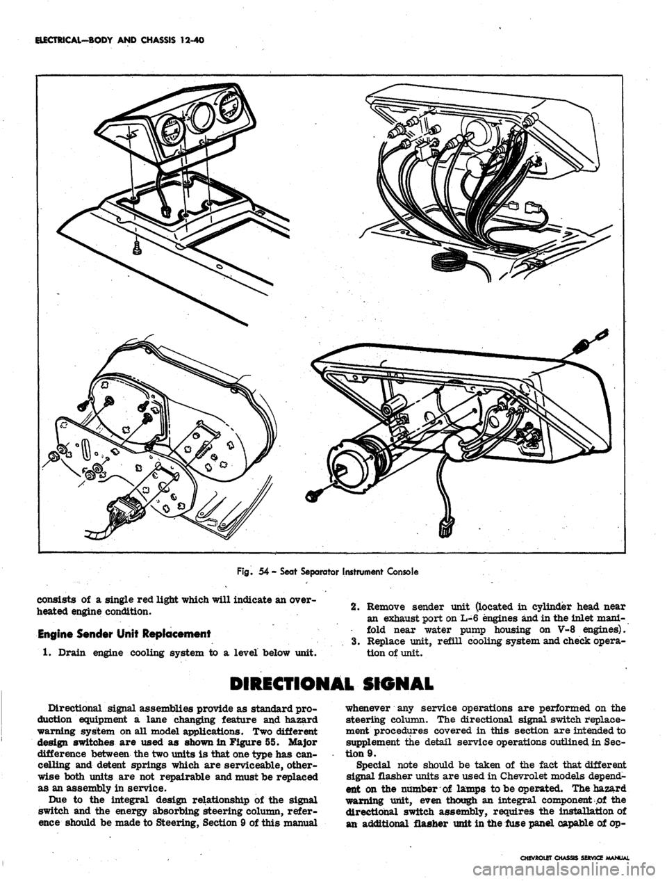
54 - Seat Separator Instrument Console
consists of a single red light which will indicate an over-
heated engine condition.
Engine Sender Unit Replacement
1.
Drain engine cooling system to a level below unit.
2.
Remove sender unit (located in cylinder head near
an exhaust port on L-6 engines and in the inlet mani-
fold near water pump housing on V-8 engines).
3.
Replace unit, refill cooling system and check opera-
tion of unit.
DIRECTIONAL SIGNAL
Directional signal assemblies provide as standard pro-
duction equipment a lane changing feature and hazard
warning system on all model applications. Two different
design switches are used as shown in Figure 55. Major
difference between the two units is that one type has can-
celling and detent springs which are serviceable, other-
wise both units are not repairable and must be replaced
as an assembly in service.
Due to the integral design relationship of the signal
switch and the energy absorbing steering column, refer-
ence should be made to Steering, Section 9 of this manual
whenever any service operations are performed on the
steering column. The directional signal switch replace-
ment procedures covered in this section are intended to
supplement the detail service operations outlined in Sec-
tion 9.
Special note should be taken of the fact that different
signal flasher units are used in Chevrolet models depend-
ent on the number of lamps to be operated. The hazard
warning unit, even though an integral component of the
directional switch assembly, requires the installation of
an additional flasher unit in the fuse panel capable of op-
CHEVROtET CHASSIS SERVICE MANUAL
Page 553 of 659

ELECTRICAL-BODY AND CHASSIS 12-41
HAZARD WARNING
SWITCHES
Fig.
55- Directional Signal Switches
erating six to eight lamps simultaneously depending ve-
hicle series and model.
DIRECTIONAL SIGNAL SWITCH REPLACEMENT
All steering columns except tilt and telescoping.
Chevrolet, Chevelle, Chevy II and Camaro (Fig. 56)
1.
Disconnect battery ground cable.
2.
Disconnect signal switch wiring from chassis har-
ness at multiple connector under instrument panel.
3.
Remove steering wheel assembly as outlined in Sec-
tion 9, Steering.
4.
Remove shift lever roll pin and shift lever from
column (if applicable).
5. Push in hazard warning switch knob and unscrew
knob.
Remove switch lever arm.
6. On Chevy U and Camaro models equipped with auto-
matic transmission remove column mounted dial in-
dicator housing and lamp assembly (if applicable).
7. Remove mast jacket lower trim cover retaining
screws and remove trim cover(s).
8. On Chevrolet and Chevelle models equipped with
automatic transmission loosen set screw and remove
quadrant dial pointer (if applicable).
9. Remove retaining
"C"
ring from upper steering shaft
using snap ring remover Tool J-22569 (Refer to
Steering, Section 9). Slide thrust and wave washers
from steering shaft.
10.
Loosen three signal switch mounting screws until
assembly can be rotated counterclockwise.
NOTE:
Do not remove three screws from as-
sembly until unit is on the bench.
11.
Rotate switch assembly counterclockwise and pull
unit from top of mast jacket. Allow unit to hang
from end of column.
Fig.
56 - Standard Steering Column
CHEVROLET CHASSIS SERVICE
Page 555 of 659
ELECTRICAL-BODY AND CHASSIS 12-43
23.
Install
MCtT
ring over steering shaft using snap ring
installer J-22659 (refer to Section 9).
NOTE: Be sure retaining ring is completely
seated into groove.
24.
Install dial pointer on Chevrolet and Chevelle models
equipped with automatic transmission (if applicable).
25.
Install dial indicator and lamp assembly on Camaro
and Chevy n models equipped with automatic
transmission.
26.
Install mast jacket lower trim covers (if applicable).
27.
Install hazard warning knob and turn signal lever.
28.
Install shift lever.
29.
Install steering wheel.
30.
Install multiple connector to switch wiring using old
harness for wire color guide and connect to body
harness connector.
31.
Connect battery ground cable and check operation of
assembly.
Tilt Steering Column (Fig. 57)
Chevrolet, Chevelle and Camaro
1.
Disconnect battery ground cable.
2.
Disconnect directional switch wiring harness from
body harness at multiple connector under instrument
panel.
3.
Remove steering wheel assembly (refer to Steering,
Section 9).
4.
Remove preload spring and cancelling cam from end
of shaft.
5.
Remove shift lever pin and lever from steering col-
umn (except floor shift).
6. Remove directional le*ver screw and lever.
7.
Push in hazard warning knob and unscrew knob.
8. On Camaro models equipped with automatic trans-
mission, remove quadrant dial and lamp assembly
from column.
9. Remove mast jacket trim cover
(s).
10.
On Chevrolet and Chevelle models with automatic
transmission, loosen set screw and remove quadrant
dial pointer.
11.
Assemble slide hammer Tool J-6585-1 to turn signal
cover remover Tool J-21486. Place cover remover
over turn signal cover, tighten clamp, and pull cover
from end of column with slide hammer (Refer to
Steering, Section 9).
12.
Remove three switch mounting screws, noting short
length of top screw.
13.
Cut multiple connector from switch wiring and slide
switch from end of column.
14.
To install new switch, feed wiring through the bear-
ing housing, around support, and through shift bowl
and shroud.
15.
Feed through wiring protector. If clearance is not
sufficient loosen mast jacket bracket retaining bolts.
16.
Insert switch wiring terminals in multiple connector.
Use old connector
and
wiring for color guide.
17.
Position switch and install three mounting screws
with short screw in top position.
18.
Be sure hazard warning switch is pushed in, then
install turn signal cover using special Tool J-21853.
On automatic columns align key in cover with keyway
in bearing housing.
19.
Install turn signal lever, hazard warning knob and
tilt lever.
20.
Install shift lever and roll pin (where applicable).
21.
Install dial pointer on Chevrolet and Chevelle. On
Camaro install dial indicator and lamp assembly.
22.
Install trim covers and retaining screws.
23.
Install cancelling cam and preload spring.
24.
Install steering wheel (Refer to Section 9).
25.
Connect switch wiring to body harness under instru-
ment panel.
26.
Connect battery ground cable and check operation of
unit.
Standard and Telescoping Steering Column
Corvette (Fig. 58)
1.
Disconnect battery ground cable.
2.
Disconnect signal switch harness wiring from chas-
sis wiring harness at multiple connector under in-
strument panel.
3.
Remove steering wheel assembly as outlined in
Steering, Section 9.
4.
Remove preload spring and cancelling cam.
5.
Remove directional signal lever screw and lever.
6. Push in hazard warning knob, unscrew and remove
knob.
7.
Remove lower trim cover retaining screws and
cover.
8. Remove retaining ring, thrust and wave washers
from upper end of shaft.
9. Cut wiring above connector.
10.
Remove three switch mounting screws, slide switch,
cover and upper bearing housing from column, pull-
ing wire through protector and escutcheon.
11.
To install replacement switch, assemble upper bear-
ing housing and turn signal switch into switch cover,
then feed wiring through escutcheon and protector
until switch can be positioned on mast jacket.
12.
With switch positioned on mast jacket, install three
switch mounting screws.
13.
Install thrust and wave washers and snap lock ring
in place.
14.
Install turn signal lever and hazard warning knob.
15.
Install cancelling cam and upper bearing preload
spring on steering shaft.
16.
Install steering wheel assembly.
NOTE:
Be sure directional signal switch is in
neutral position before installing wheel.
17.
Install connector on directional signal wiring har-
ness and connect to body harness connector.
CHEVROLET CHASSIS SERVICE
Page 578 of 659
ELECTRICAL-BODY
AND
CHASSIS
12-66
R.H. PARK
&DIR.
SIG. LP
L.H. PARK
& DQU SIG.
LP,
GROUND
TO
FENDER REINF
BRAKE FLUID
ill WARNING SW.
Fig.
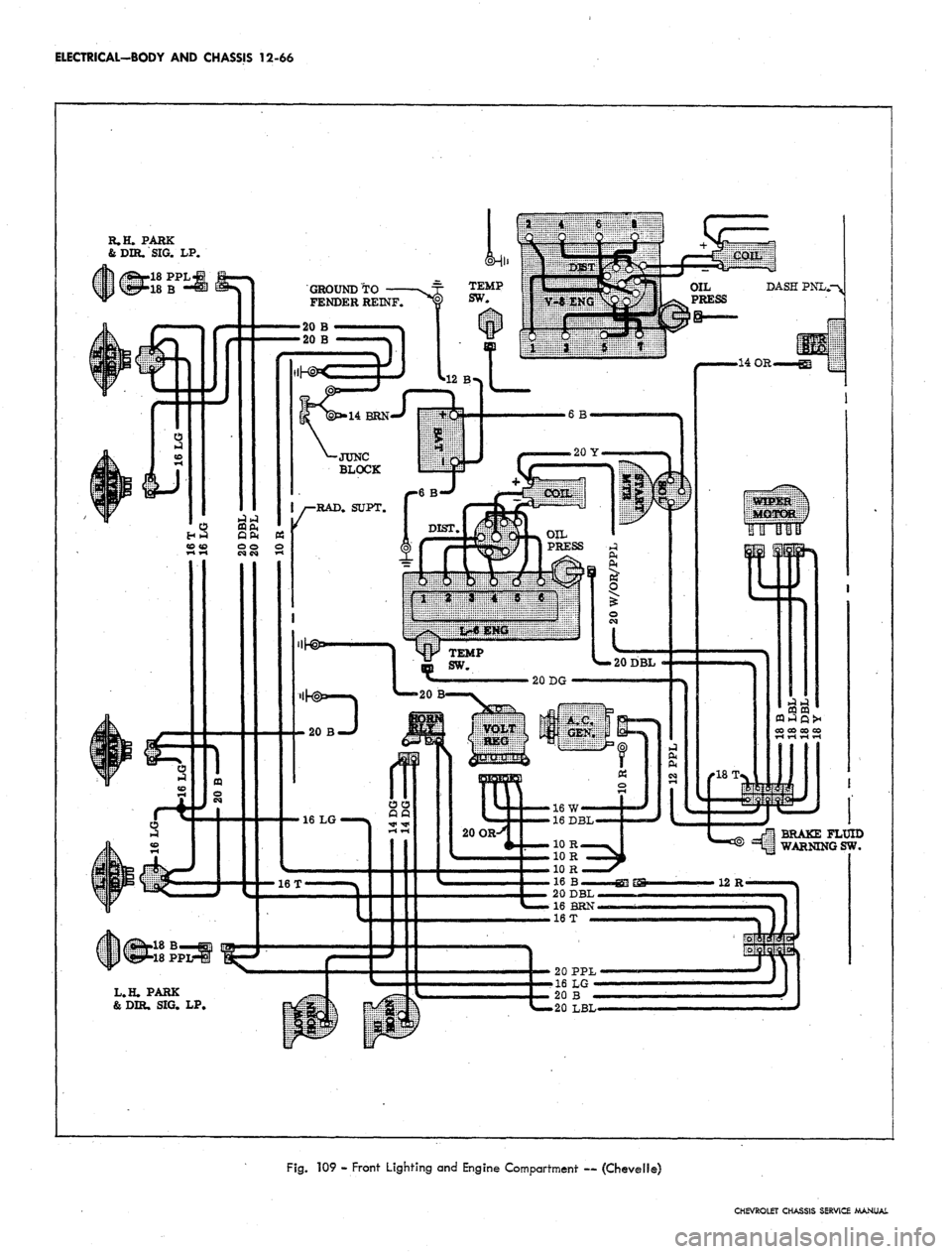
109 - Front Lighting and Engine Compartment — (Chevelie)
CHEVROLET CHASSIS SERVICE MANUAL
Page 586 of 659
ELECTRICAL-BODY AND CHASSIS 12-74
R.H. PARK&
DIR. SIG. LAMP
\L2 BRNf
18 Y—
12 BRN
18 LBL4-
18DBL
12 P
18 LG
18 P
DASH
PANEL
RESISTOR
TEMP.
SENDER
R.H. LIMIT SW.
L.H. LIMIT SW.
GY/B,
16 DBL
BRK FLUID
WARNING
16
W
20 OR
20 B
BACK-UP
LMP.
SW,
20 B
16 B/W
18 T
NEU.
SFT.
SW. I
RPO
M35
4BRN/W
16 B
M18DG
4 OR
DIR. SIG.
&
DIR.
SIG. LAMP
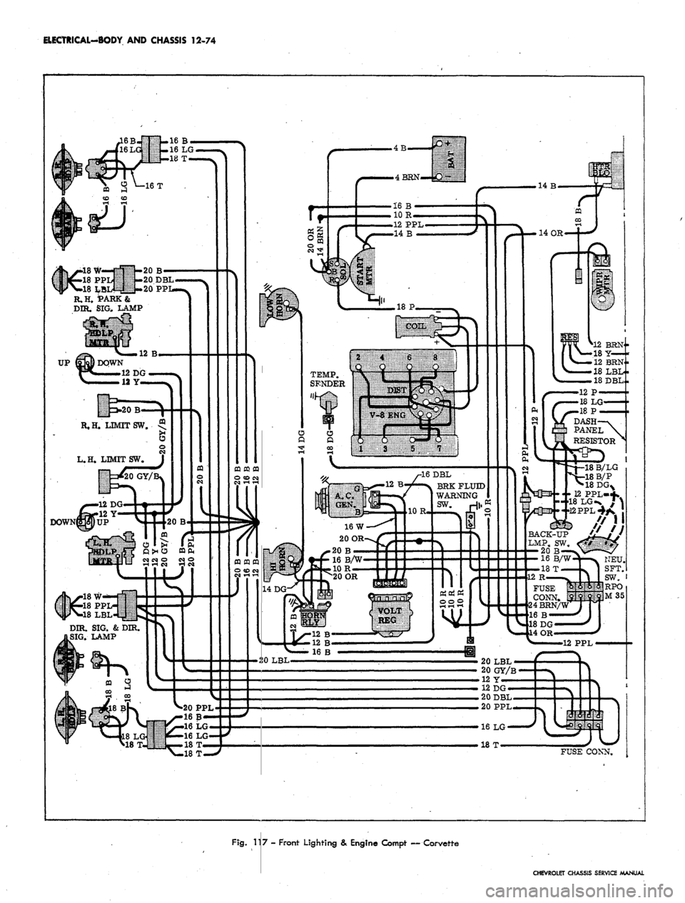
Fig. 117 - Front Lighting & Engine Compt — Corvette
CHEVROLET CHASSIS SERVICE MANUAL
Page 653 of 659
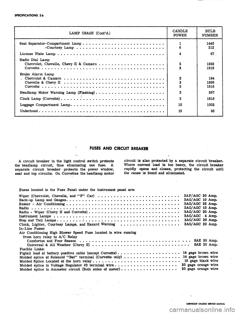
SPECIFICATIONS 26
LAMP USAGE (Cont'd.)
CANDLE
POWER
1
6
4
2
3
2
2
3
2
3
15
15
BULB
NUMBER
1445
212
67
1893
1816
194
1895
1816
257
1816
1003
93
Seat Separator-Compartment Lamp . . . . .
-Courtesy Lamp •
License Plate Lamp . .
Radio Dial Lamp
Chevrolet, Chevelle, Chevy n & Camaro
Corvette
Brake Alarm Lamp
. Chevrolet & Camaro . . .... . .
Chevelle & Chevy n . . . . .'. ;v . . . .
Corvette . . . . . . . .
Headlamp Mqtor Warning Lamp (Flashing) .
Clock Lamp (Corvette) .''> ....
Luggage Compartment Lamp. . ... . . . •
Underhood
FUSES AND CIRCUIT BREAKER
A circuit breaker in the light control switch protects
the headlamp circuit, thus eliminating one fuse. A
separate circuit breaker protects the power window,
seat and top circuits. On Corvettes the headlamp motor
circuit is also protected by a separate circuit breaker.
Where current load is too heavy, the circuit breaker
rapidly opens and closes, protecting the circuit until
the cause is found and eliminated.
louses located in the Fuse Panel under the instrument panel are:
Wiper (Chevrolet, Chevelle, and "F" Car) 3AF/AGC 20 Amp.
Back-up Lamp and Gauges. . . 3AG/AGC 10 Amp.
Heater - Air Conditioning 3AG/AGC 25 Amp.
Radio 3AG/AGC 10 Amp.
Radio - Wiper (Chevy II and Corvette) 3AG/AGC 20 Amp.
Instrument Lamps 3AG/AGC . 4 Amp.
Stop and Tail Lamps ........ t 3AG/AGC 20 Amp.
Clock, Lighter, Courtesy Lamps, and Hazard Warning 3AG/AGC 20 Amp.
In-Line Fuses:
Air Conditioning High Blower Speed Fuse located in wire running
from horn relay to A/C Relay
Comforton and Four Season SAE 30 Amp.
Universal & All Weather (Chevy H) SAE 20 Amp.
Fusible Links: ,
Pigtail lead at battery positive cable (except Corvette) 14 gage brown wire
Molded splice at Solenoid "Bat" terminal (Corvette only) 14 gage brown wire
Molded Splice Located at the horn relay 16 gage black wire
Molded splice in Voltage Regulator #3 terminal wire 20 gage orange wire
Molded splice in Ammeter circuit (Both sides of meter) 20 gage orange wire
CHEVROLET CHASSIS SERVICE MANUAL