drain bolt CHEVROLET CAMARO 1967 1.G Chassis Owner's Guide
[x] Cancel search | Manufacturer: CHEVROLET, Model Year: 1967, Model line: CAMARO, Model: CHEVROLET CAMARO 1967 1.GPages: 659, PDF Size: 114.24 MB
Page 594 of 659

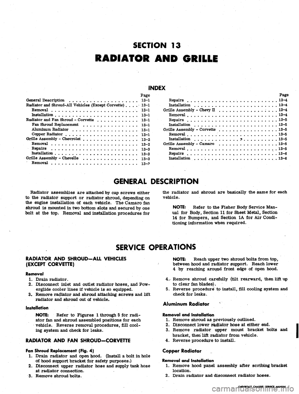
SECTION 13
RADIATOR AND GRILLE
INDEX
Page Page
General Description 13-1 Repairs 13-4
Radiator and Shroud-All Vehicles (Except Corvette) . . . . 13-1 Installation 13-4
Removal 13-1 Grille Assembly - Chevy II 13-4
Installation 13-1 Removal . 13-4
Radiator and Fan Shroud - Corvette . . . . 13-1 Repairs 13-5
Fan Shroud Replacement 13-1 Installation . 13-5
Aluminum Radiator 13-1 Grille Assembly - Corvette 13-5
Copper Radiator . 13-1 Removal . . . . 13-5
Grille Assembly - Chevrolet 13-2 Installation ....*... 13-5
Removal 13-2 Grille Assembly - Caxnaro 13-5
Repairs 13-3 Removal 13-5
Installation 13-3 Repairs . 13-6
Grille Assembly - Chevelle 13-3 Installation . . 13-6
Removal 13-.Q
GENERAL DESCRIPTION
Radiator assemblies are attached by cap screws either the radiator and shroud are basically the same for each
to the radiator support or radiator shroud, depending on vehicle,
the engine installation of each vehicle. The Camaro fan
Shroud is mounted in two bottom slots and secured by one NOTE: Refer to the Fisher Body Service Man-
bolt at the top. Removal and installation procedures for ual for Body, Section IX for Sheet Metal, Section
14 for Bumpers, and Section 1A for Air Condi-
tioning information when required.
SERVICE OPERATIONS
RADIATOR
AND
SHROUD—ALL VEHICLES
NOTE: Reach upper two shroud bolts from top,
(EXCEPT CORVETTE)
between hood and radiator support. Reach lower
4 by reaching around front edge of open hood.
Removal
1.
Drain radiator. 4.- Remove shroud carefully (tilt rearward, then lift up
2.
Disconnect inlet and outlet radiator hoses, and Pow- to clear fan blades).
erglide cooler lines if vehicle is so equipped. 5. Reverse procedure to install, fill cooling system and
3.
Remove radiator and shroud attaching screws and lift check for leaks.
radiator and shroud out of vehicle.
Aluminum Radiator
Installation
NOTE:
Refer to Figures 1 through 5 for radi- Removal and Installation
ator fan and shroud assembled positions for each 1. Remove shroud as previously outlined.
vehicle. Reverse removal procedures, fill cool- 2. Disconnect lower raciiator hose at either end.
ing system and check for leaks. 3. Remove radiator upper mount bracket bolts and
bracket, then lift radiator from vehicle.
RADIATOR AND FAN SHROUD-CORVETTE 4. Reverse procedure to install.
Fan Shroud Replacement (Fig. 4) Copper Radiator
1.
Drain radiator and open hood. (Install a bolt in hole
of hood support bracket for safety purposes.) Removal and Installation
2.
Disconnect upper radiator hose and supply tank hose 1. Remove hood panel assembly after scribing bracket
at radiator connection. location.
3.
Remove shroud bolts. 2. Drain radiator and disconnect radiator hoses.
CHEVROLET CHASSIS SERVICE MANUAL
Page 644 of 659

SPECIFICATIONS 17
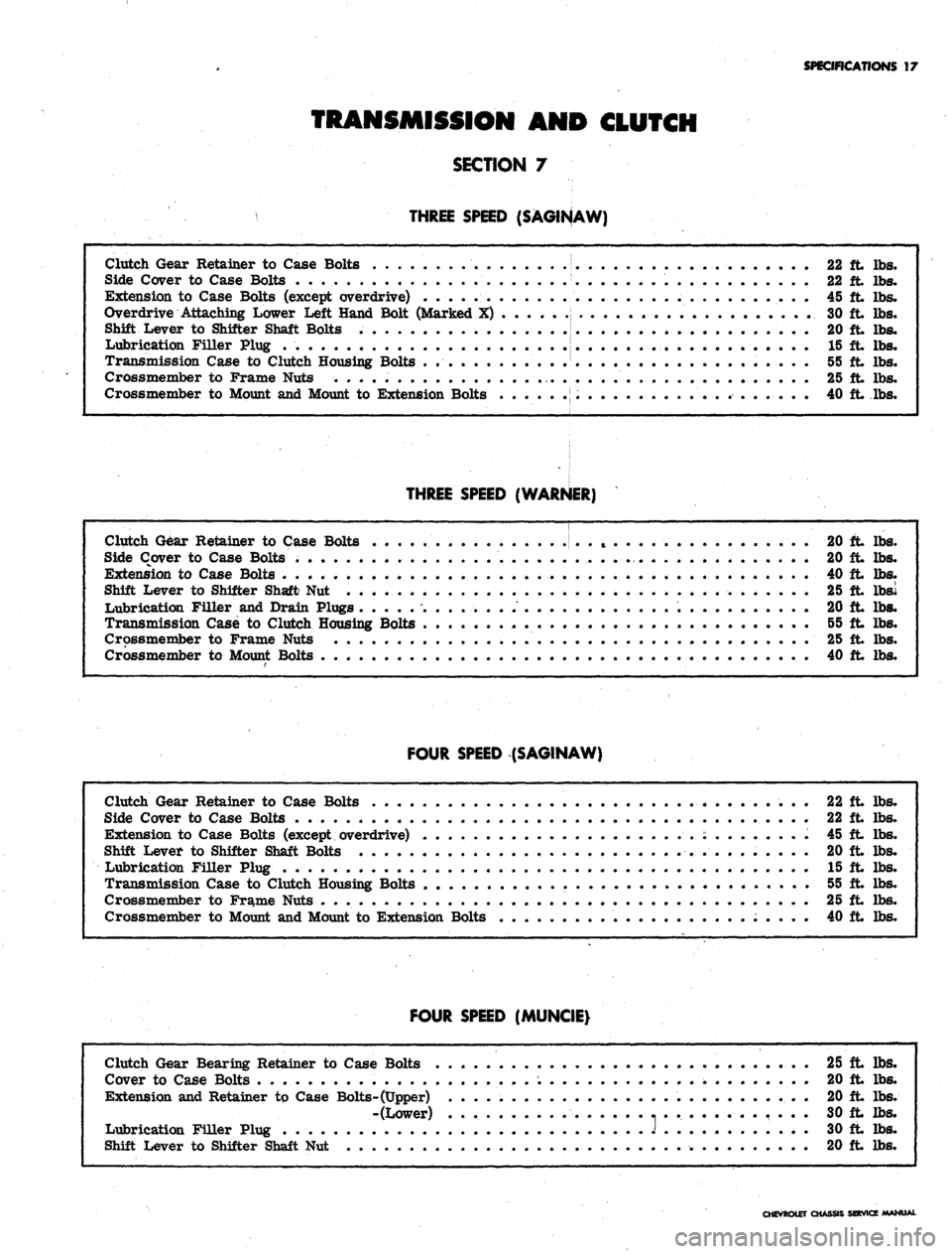
TRANSMISSION AND CLUTCH
SECTION 7
THREE SPEED (SAGINAW)
Clutch Gear Retainer to Case Bolts 22 ft lbs.
Side Cover to Case Bolts . . 22 ft lbs.
Extension to Case Bolts (except overdrive) . . . . 45 ft lbs.
Overdrive Attaching Lower Left Hand Bolt (Marked X) . 30 ft lbs.
Shift Lever to Shifter Shaft Bolts 20 ft lbs.
Lubrication Filler Plug . . . . 15 ft lbs.
Transmission Case to Clutch Housing Bolts 55 ft lbs.
Crossmember to Frame Nuts . . • 25 ft lbs.
Crossmember to Mount and Mount to Extension Bolts 40 ft lbs.
THREE SPEED (WARNER)
Clutch Gear Retainer to Case Bolts . t . . . 20 ft lbs.
Side Cover to Case Bolts 20 ft lbs.
Extension to Case Bolts . . 40 ft lbs.
Shift Lever to Shifter Shaft Nut 25 ft lbsi
Lubrication Filler and Drain Plugs 20 ft lbs.
Transmission Case to Clutch Housing Bolts 55 ft lbs.
Crossmember to Frame Nuts 25 ft lbs.
Crossmember to Mount Bolts 40 ft lbs.
FOUR SPEED (SAGINAW)
Clutch Gear Retainer to Case Bolts 22 ft lbs.
Side Cover to Case Bolts 22 ft lbs.
Extension to Case Bolts (except overdrive) ' . : 45 ft lbs.
Shift Lever to Shifter Shaft Bolts 20 ft lbs.
Lubrication Filler Plug . 15 ft lbs.
Transmission Case to Clutch Housing Bolts . 55 ft lbs.
Crossmember to Frame Nuts 25 ft lbs.
Crossmember to Mount and Mount to Extension Bolts 40 ft lbs.
FOUR SPEED (MUNCIE)
Clutch Gear Bearing Retainer to Case Bolts 25 ft lbs.
Cover to Case Bolts . 20 ft lbs.
Extension and Retainer tp Case Bolts-(Upper) . 20 ft lbs.
-(Lower) 30 ft lbs.
Lubrication Filler Plug J 30 ft lbs.
Shift Lever to Shifter Shaft Nut 20 ft lbs.
CHEVROLET CHASSIS SERVICE MANUAL
Page 645 of 659

SPECIFICATIONS
18
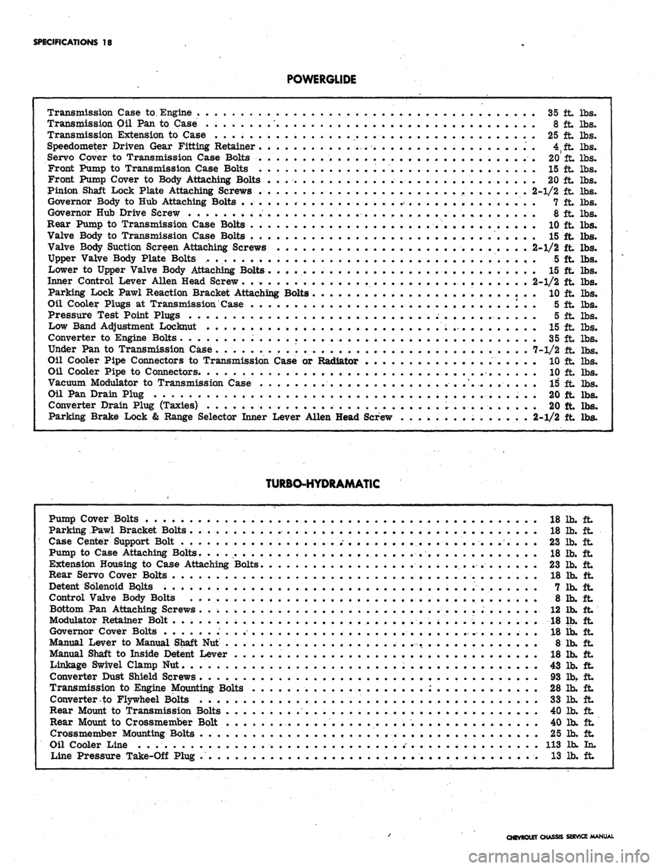
POWERGLIDE
Transmission Case to. Engine
35 ft. lbs.
Transmission
Oil Pan to
Case
* 8 ft lbs.
Transmission Extension
to
Case
25 ft lbs.
Speedometer Driven Gear Fitting Retainer
'.....- .......
4fft
lbs.
Servo Cover
to
Transmission Case Bolts
.....*.........
20 ft lbs.
Front Pump
to
Transmission Case Bolts
... 15 It lbs.
Front Pump Cover
to
Body Attaching Bolts
. . ..•. 20 ft lbs.
Pinion Shaft Lock Plate Attaching Screws
. . . 2-1/2 ft lbs.
Governor Body
to Hub
Attaching Bolts
•„•••........
7 ft lbs.
Governor
Hub
Drive Screw
8 ft lbs.
Rear Pump
to
Transmission Case Bolts
. •
..........
10 ft lbs.
Valve Body
to
Transmission Case Bolts
15 ft lbs.
Valve Body Suction Screen Attaching Screws
. . . . * . . 2-1/2 ft lbs.
Upper Valve Body Plate Bolts
5 ft lbs.
Lower
to
Upper Valve Body Attaching Bolts
15 ft lbs.
Inner Control Lever Allen Head Screw
2-1/2 ft lbs.
Parking Lock Pawl Reaction Bracket Attaching Bolts
10 ft lbs.
Oil Cooler Plugs
at
Transmission Case
. I . . 5 ft lbs.
Pressure Test Point Plugs
.
•-,•••
• •" 5 ft lbs.
Low Band Adjustment Locknut
.....;.
15 ft lbs.
Converter
to
Engine Bolts
......................
i . 35 ft lbs.
Under
Pan to
Transmission Case.
7-1/2 ft lbs.
Oil Cooler Pipe Connectors
to
Transmission Case
or
Radiator
10 ft lbs.
Oil Cooler Pipe
to
Connectors
10 ft lbs.
Vacuum Modulator
to
Transmission Case
15 ft lbs.
Oil
Pan
Drain Plug
20 ft lbs.
Converter Drain Plug (Taxies)
^
.........
20 ft lbs.
Parking Brake Lock
&
Range Selector Inner Lever Allen Head Screw
. . . »..,
......
... . 2-1/2 ft lbs.
TURBO-HYDRAMATIC
Pump Cover Bolts
18 lb. ft
Parking Pawl Bracket Bolts
18 Ib. ft
Case Center Support Bolt
. . .
......
. . . .
<
. . . . .
.........
. 23 lb. ft
Pump
to
Case Attaching Bolts.
. . ..- 18 lb. ft
Extension Housing
to
Case Attaching Bolts.
23 lb. ft
Rear Servo Cover Bolts
. . . . . . . 18 lb. ft
Detent Solenoid Bolts
7 lb. ft
Control Valve Body Bolts
8 lb. ft
Bottom
Pan
Attaching Screws
.. \ 12 lb. ft
Modulator Retainer Bolt
.*........
; . . . . . . . 18 lb. ft
Governor Cover Bolts
...........................
18 ib. ft
Manual Lever
to
Manual Shaft
Nut . . 8 lb. ft
Manual Shaft
to
Inside Detent Lever
. 18 lb. ft
Linkage Swivel Clamp
Nut 43 lb. ft
Converter Dust Shield Screws
93 lb. ft
Transmission
to
Engine Mounting Bolts
:............
28 lb. ft
Converter-to Flywheel Bolts
. . 33 lb. ft
Rear Mount
to
Transmission Bolts
. . . . 40 lb. ft
Rear Mount
to
Crossmember Bolt
* 40 lb. ft
Crossmember Mounting Bolts . .
...............
25 lb. ft
Oil Cooler Line . . . .' 113 lb. In.
Line Pressure Take-Off Plug . . .... 13 lb. ft
CHEVROLET CHASSIS SERVICE MANUAL