brakes CHEVROLET CAMARO 1967 1.G Chassis Workshop Manual
[x] Cancel search | Manufacturer: CHEVROLET, Model Year: 1967, Model line: CAMARO, Model: CHEVROLET CAMARO 1967 1.GPages: 659, PDF Size: 114.24 MB
Page 19 of 659
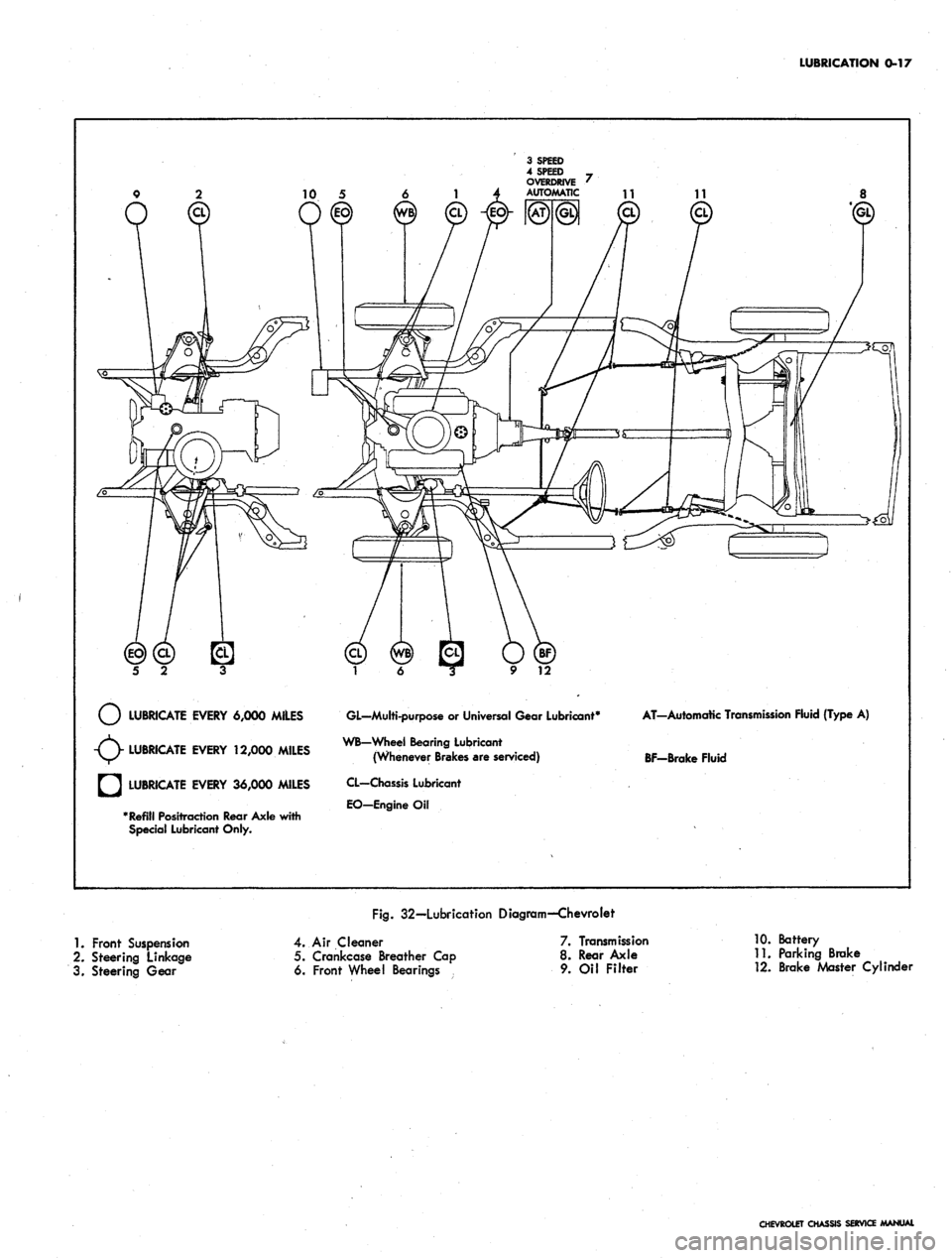
LUBRICATION 0-17
LUBRICATE EVERY 6,000 MILES
LUBRICATE EVERY 12,000 MILES
LUBRICATE EVERY 36,000 MILES
Refill Positraction Rear Axle with
Special Lubricant Only.
GL—Multi-purpose
or
Universal Gear Lubricant4
WB-Wheel Bearing Lubricant
(Whenever Brakes are serviced)
CL—Chassis Lubricant
EO-EngineOil
AT-Automatic Transmission Fluid {Type
A)
BF-Brake Fluid
Fig.
32—Lubrication Diagram—Chevrolet
1.
Front Suspension
2.
Steering Linkage
3. Steering Gear
4.
Air Cleaner
5. Crankcase Breather Cap
6. Front Wheel Bearings
7. Transmission
8. Rear Axle
9. Oil Filter
10.
Battery
11.
Parking Brake
12.
Brake Master Cylinder
CHEVROLET CHASSIS SERVICE MANUAL
Page 20 of 659
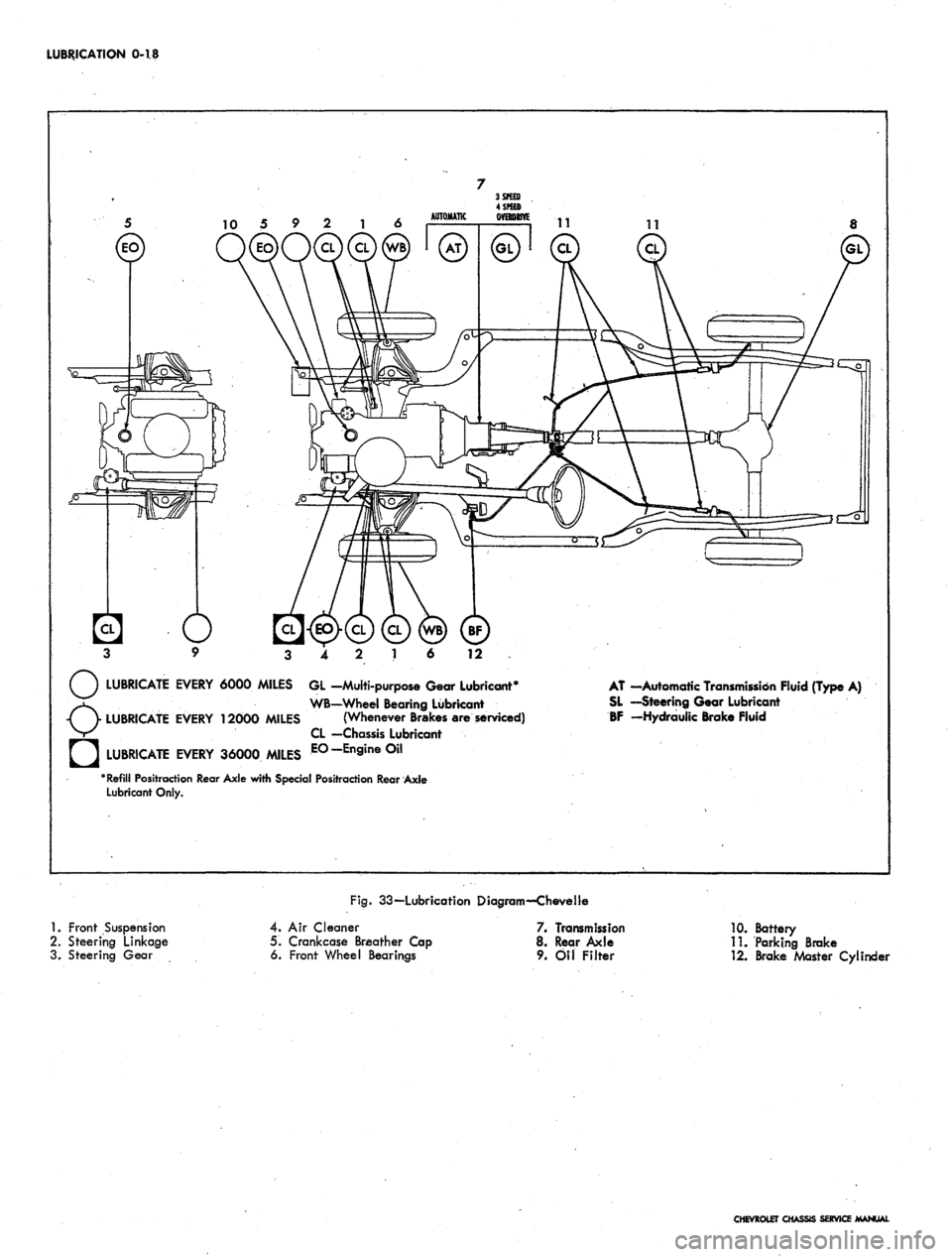
LUBRICATION 0-18
12
LUBRICATE EVERY 6000 MILES GL -Multi-purpose Gear Lubricant*
WB—Wheel Bearing Lubricant
LUBRICATE EVERY 12000 MILES (Whenever Brakes are serviced)
CL —Chassis Lubricant
LUBRICATE EVERY 36000 MILES E°-En9ine°il
"Refill Positraction Rear Axle with Special Positraction Rear Axle
Lubricant Only.
AT —Automatic Transmission Fluid (Type A)
SL —Steering Gear Lubricant
BF -Hydraulic Brake Fluid
1.
Front Suspension
2.
Steering Linkage
3. Steering Gear
Fig.
33—Lubrication Diagram—Chevelle
4.
Air Cleaner
5. Crankcase Breather Cap
6. Front Wheel Bearings
7. Transmission
8. Rear Axle
9. Oil Filter
10.
Battery
11.
Parking Brake
12.
Brake Master CylincU
CHEVROLET CHASSIS SERVICE MANUAL
Page 21 of 659
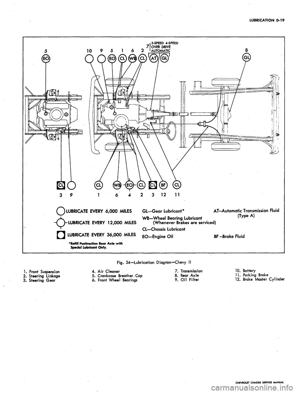
LUBRICATION
0-19
.
3-SPEED
4-SPEED
7 OVER DRIVE
10 9 5 1 6 2 '
AUTOMATIC
3 12 11
LUBRICATE EVERY 6,000 MILES GL-Gear Lubricant*
WB-Wheel Bearing Lubricant
(Wh Bk
AT-Automdtic Transmission Fluid
^ WB-Wheel Bearing Lubricant (Type A)
-TV
LUBRICATE
EVERY 12,000 MILES (Whenever Brakes are serviced)
' CL—Chassis Lubricant
• LUBRICATE EVERY 36,000 MILES EO_Engine Oil
BF
-Brake Fluid
•Refill Positt
Special Lubricant Only.
Axl«
with
1.
Front Suspension
2.
Steering Linkage
3. Steering Gear
Fig.
34—Lubrication Diagram—Chevy I!
4. Air Cleaner
5. Crankcase Breather. Cap
6. Front Wheel Bearings
7. Transmission
8. Rear Axle
9.
Oil Filter
10.
Battery
11.
Parking Brake
12.
Brake Master Cylinder
CHEVROLET CHASSIS SERVICE MANUAL
Page 22 of 659
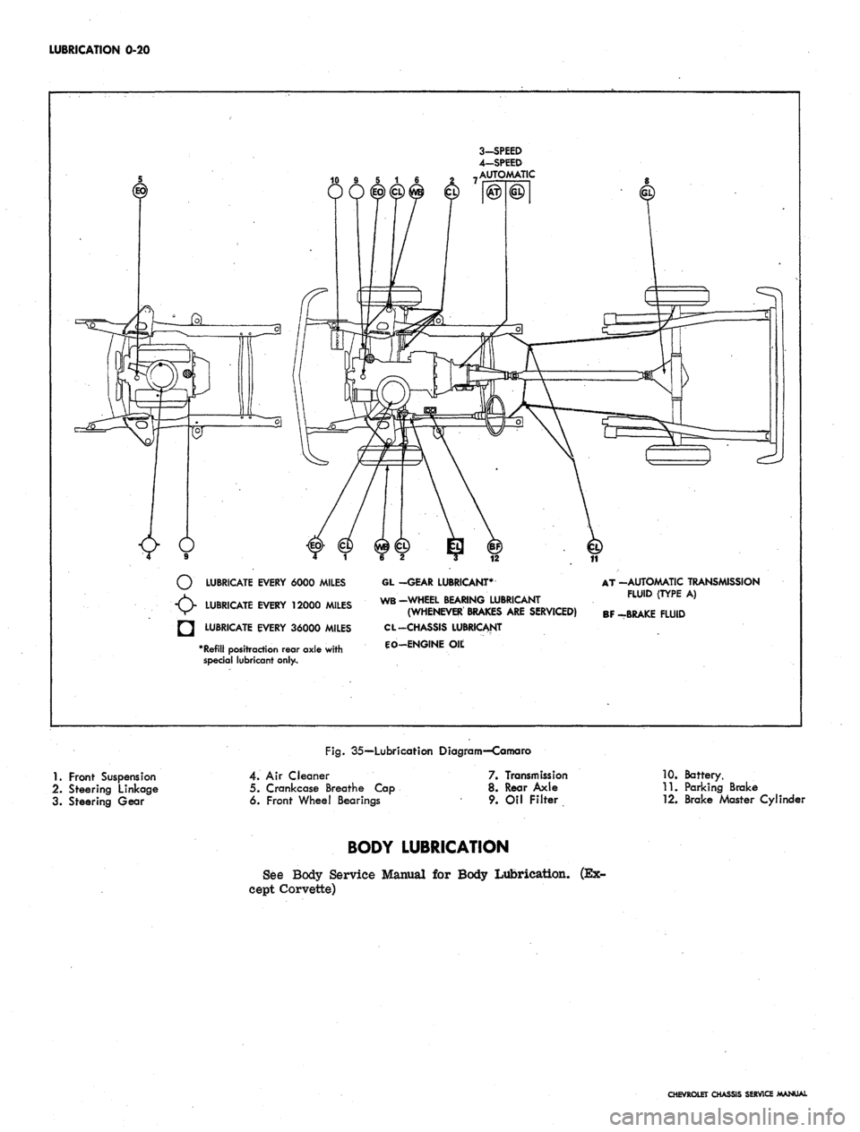
LUBRICATION 0-20
3-SPEED
4—SPEED
AUTOMATIC
LUBRICATE EVERY 6000 MILES
LUBRICATE EVERY 12000 MILES
LUBRICATE EVERY 36000 MILES
*
Refill
positraction rear axle with
special lubricant only.
GL -GEAR LUBRICANT*
WB-WHEEL BEARING LUBRICANT
(WHENEVER BRAKES
ARE
SERVICED)
CL -CHASSIS LUBRICANT
CO-ENGINE
Oil;
AT -AUTOMATIC TRANSMISSION
FLUID (TYPE
A)
BF -BRAKE FLUID
Fig.
35—Lubricafion Diagram—Camaro
1.
Front Suspension
2.
Steering Linkage
3. Steering Gear
4.
Air Cleaner
5. Crankcase Breathe Cap
6. Front Wheel Bearings
7. Transmission
8. Rear Axle
9. Oil Filter
10.
Battery,
11.
Parking Brake
12.
Brake Master Cylinder
BODY LUBRICATION
See Body Service Manual
for
Body Lubrication,
cept Corvette)
(Ex-
CHEVROLET CHASSIS SERVICE MANUAL
Page 23 of 659
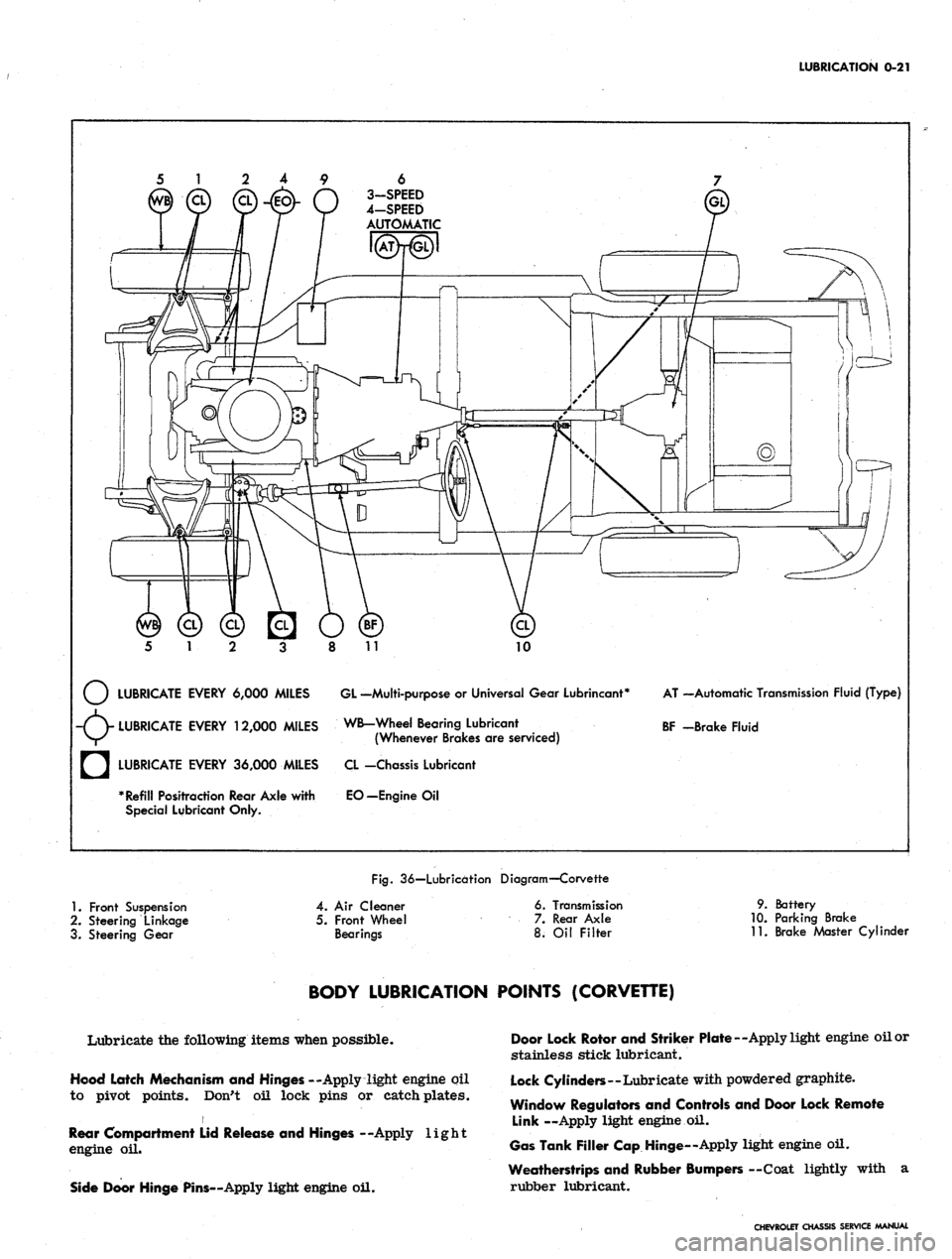
LUBRICATION
0-21
6
3-SPEED
4-SPEED
AUTOMATIC
10
LUBRICATE EVERY 6,000 MILES GL -Multi-purpose
or
Universal Gear Lubrincant*
-(V LUBRICATE EVERY 12,000 MILES WB-Wheel Bearing Lubricant
V/^ (Whenever Brakes
are
serviced)
AT —Automatic Transmission Fluid (Type)
BF -Brake Fluid
a
LUBRICATE EVERY 36,000 MILES
* Refill Positraction Rear Axle with
Special Lubricant Only.
CL -Chassis Lubricant
EO—Engine
Oil
Fig.
36—Lubrication Diagram—Corvette
1.
Front Suspension
2.
Steering Linkage
3. Steering Gear
4.
Air
Cleaner
5. Front Wheel
Bearings
6. Transmission
7. Rear Axle
8.
Oil
Filter
9. Battery
10.
Parking Brake
11.
Brake Master Cylinder
BODY LUBRICATION POINTS (CORVETTE)
Lubricate the following items when possible.
Hood Latch Mechanism and Hinges --Apply light engine oil
to pivot points. Don't oil lock pins or catch plates.
i
Rear Compartment Lid Release and Hinges --Apply light
engine
oil.
Side Door Hinge Pins—Apply light engine oil.
Door Lock Rotor and Striker Plate—Apply light engine oil or
stainless stick lubricant.
Lock Cylinders—Lubricate with powdered graphite.
Window Regulators and Controls and Door Lock Remote
Link —Apply light engine
oil.
Gas Tank Filler Cap Hinge—Apply light engine oil.
Weatherstrips and Rubber Bumpers —Coat lightly with
a
rubber lubricant.
CHEVROLET CHASSIS SERVICE MANUAL
Page 214 of 659
REAR SUSPENSION AND DRIVE LINE 4-24
4
i*
5
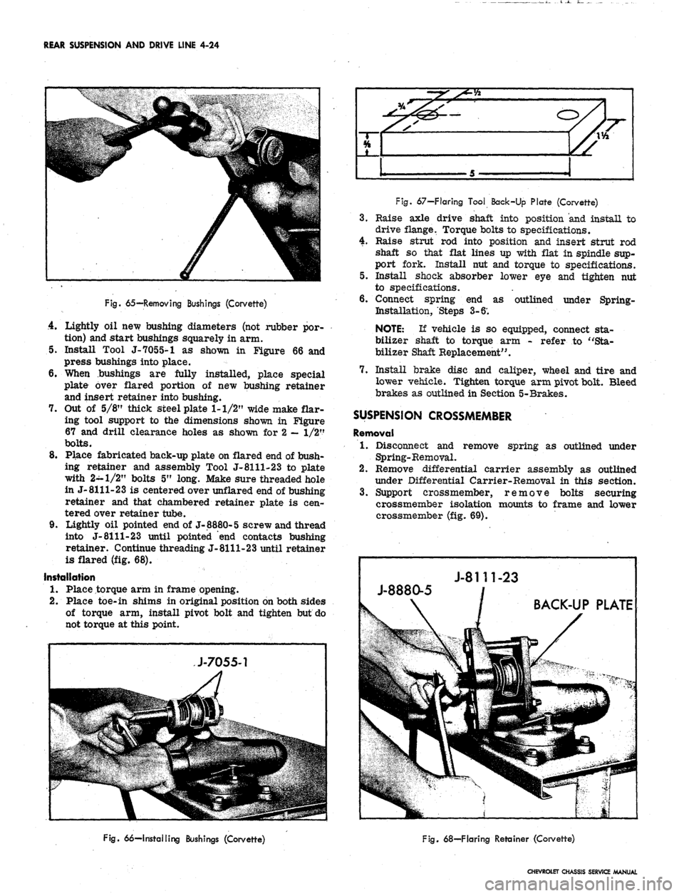
Fig.
65—Removing Bushings (Corvette)
4.
Lightly oil new bushing diameters (not rubber por-
tion) and start bushings squarely in arm.
5. Install Tool J-7055-1 as shown in Figure 66 and
press bushings into place.
6. When bushings are fully installed, place special
plate over flared portion of new bushing retainer
and insert retainer into bushing.
7. Out of 5/8" thick steel plate 1-1/2" wide make flar-
ing tool support to the dimensions shown in Figure
67 and drill clearance holes as shown for 2
—
1/2"
bolts.
8. Place fabricated back-up plate on flared end of bush-
ing retainer and assembly Tool J-8111-23 to plate
with 2-1/2" bolts 5" long. Make sure threaded hole
in J-8111-23 is centered over unflared end of bushing
retainer and that chambered retainer plate is cen-
tered over retainer tube.
9. Lightly oil pointed end of J-8880-5 screw and thread
into J-
8111-23
until pointed "end contacts bushing
retainer. Continue threading J-8111-23 until retainer
is flared (fig. 68).
Installation
1.
Place torque arm in frame opening.
2.
Place toe-in shims in original position on both sides
of torque arm, install pivot bolt and tighten but do
not torque at this point.
Fig.
67—Flaring Tool Back-Up Plate (Corvette)
3.
Raise axle drive shaft into position and install to
drive flange. Torque bolts to specifications.
4.
Raise strut rod into position and insert strut rod
shaft so that flat lines up with flat in spindle sup-
port fork. Install nut and torque to specifications.
5. Install shock absorber lower eye and tighten nut
to specifications.
6. Connect spring end as outlined under Spring-
Bistallation, Steps 3-6'.
NOTE:
If vehicle is so equipped, connect sta-
bilizer shaft to torque arm - refer to "Sta-
bilizer Shaft Replacement".
7. Install brake disc and caliper, wheel and tire and
lower vehicle. Tighten torque arm pivot bolt. Bleed
brakes as outlined in Section 5-Brakes.
SUSPENSION CROSSMEMBER
Removal
1.
Disconnect and remove spring as outlined under
Spring-Removal.
2.
Remove differential carrier assembly as outlined
under Differential Carrier-Removal in this section.
3.
Support crossmember, remove bolts securing
crossmember isolation mounts to frame and lower
crossmember (fig. 69).
Fig.
66—Installing Bushings (Corvette)
Fig.
68—Flaring Retainer (Corvette)
CHEVROLET CHASSIS SERVICE MANUAL
Page 220 of 659
REAR SUSPENSION AND DRIVE LINE 4-30
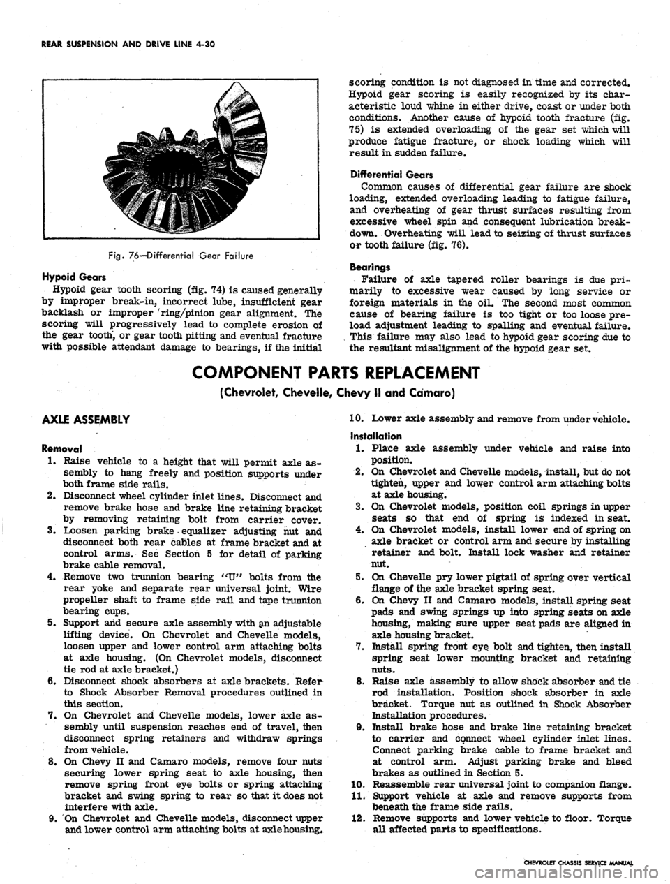
Fig.
76—Differential Gear Failure
Hypoid Gears
Hypoid gear tooth scoring (fig. 74) is caused generally
by improper break-in, incorrect lube, insufficient gear
backlash or improper 'ring/pinion gear alignment. The
scoring will progressively lead to complete erosion of
the gear tooth, or gear tooth pitting and eventual fracture
with possible attendant damage to bearings, if the initial
scoring condition is not diagnosed in time and corrected.
Hypoid gear scoring is easily recognized by its char-
acteristic loud whine in either drive, coast or under both
conditions. Another cause of hypoid tooth fracture (fig.
75) is extended overloading of the gear set which will
produce fatigue fracture, or shock loading which will
result in sudden failure.
Differential Gears
Common causes of differential gear failure are shock
loading, extended overloading leading to fatigue failure,
and overheating of gear thrust surfaces resulting from
excessive wheel spin and consequent lubrication break-
down. Overheating will lead to seizing of thrust surfaces
or tooth failure (fig. 76).
Bearings
• Failure of axle tapered roller bearings is due pri-
marily to excessive wear caused by long service or
foreign materials in the oil. The second most common
cause of bearing failure is too tight or too loose pre-
load adjustment leading to spalling and eventual failure.
This failure may also lead to hypoid gear scoring due to
the resultant misalignment of the hypoid gear set.
COMPONENT PARTS REPLACEMENT
(Chevrolet, Cheveile, Chevy II and Camaro)
AXLE ASSEMBLY
Removal
1.
Raise vehicle to a height that will permit axle as-
sembly to hang freely and position supports under
both frame side rails.
2.
Disconnect wheel cylinder inlet lines. Disconnect and
remove brake hose and brake line retaining bracket
by removing retaining bolt from carrier cover.
3.
Loosen parking brake equalizer adjusting nut and
disconnect both rear cables at frame bracket and at
control arms. See Section 5 for detail of parking
brake cable removal.
4.
Remove two trunnion bearing "U" bolts from the
rear yoke and separate rear universal joint. Wire
propeller shaft to frame side rail and tape trunnion
bearing cups.
5. Support arid secure axle assembly with an adjustable
lifting device. On Chevrolet and Cheveile models,
loosen upper and lower control arm attaching bolts
at axle housing. (On Chevrolet models, disconnect
tie rod at axle bracket.)
6. Disconnect shock absorbers at axle brackets. Refer
to Shock Absorber Removal procedures outlined in
this section.
7. On Chevrolet and Cheveile models, lower axle as-
sembly until suspension reaches end of travel, then
disconnect spring retainers and withdraw springs
from vehicle.
8. On Chevy II and Camaro models, remove four nuts
securing lower spring seat to axle housing, then
remove spring front eye bolts or spring attaching
bracket and swing spring to rear so that it does not
interfere with axle.
9. On Chevrolet and Cheveile models, disconnect upper
and lower control arm attaching bolts at axle housing*
10.
Lower axle assembly and remove from under vehicle.
Installation
1.
Place axle assembly under vehicle and raise into
position.
2.
On Chevrolet and Cheveile models, install, but do not
tighten, upper and lower control arm attaching bolts
at axle housing.
3.
On Chevrolet models, position coil springs in upper
seats so that end of spring is indexed in seat.
4.
On Chevrolet models, install lower end of spring on
axle bracket or control arm and secure by installing
retainer and bolt. Install lock washer and retainer
nut.
5. On Cheveile pry lower pigtail of spring over vertical
flange of the axle bracket spring seat.
6. On Chevy II and Camaro models, install spring seat
pads and swing springs up into spring seats on axle
housing, making sure upper seat pads are aligned in
axle housing bracket.
7. Install spring front eye bolt and tighten, then install
spring seat lower mounting bracket and retaining
nuts.
8. Raise axle assembly to allow shock absorber and tie
rod installation. Position shock absorber in axle
bracket. Torque nut as outlined in Shock Absorber
Installation procedures.
9. Install brake hose and brake line retaining bracket
to carrier and connect wheel cylinder inlet lines.
Connect parking brake cable to frame bracket and
at control arm. Adjust parking brake and bleed
brakes as outlined in Section 5.
10.
Reassemble rear universal joint to companion flange.
11.
Support vehicle at axle and remove supports from
beneath the frame side rails.
12.
Remove supports and lower vehicle to floor. Torque
all affected parts to specifications.
CHEVROLET CHASSIS SERVICE MANUAL
Page 222 of 659
REAR SUSPENSION AND DRIVE LINE 4-32
HP?
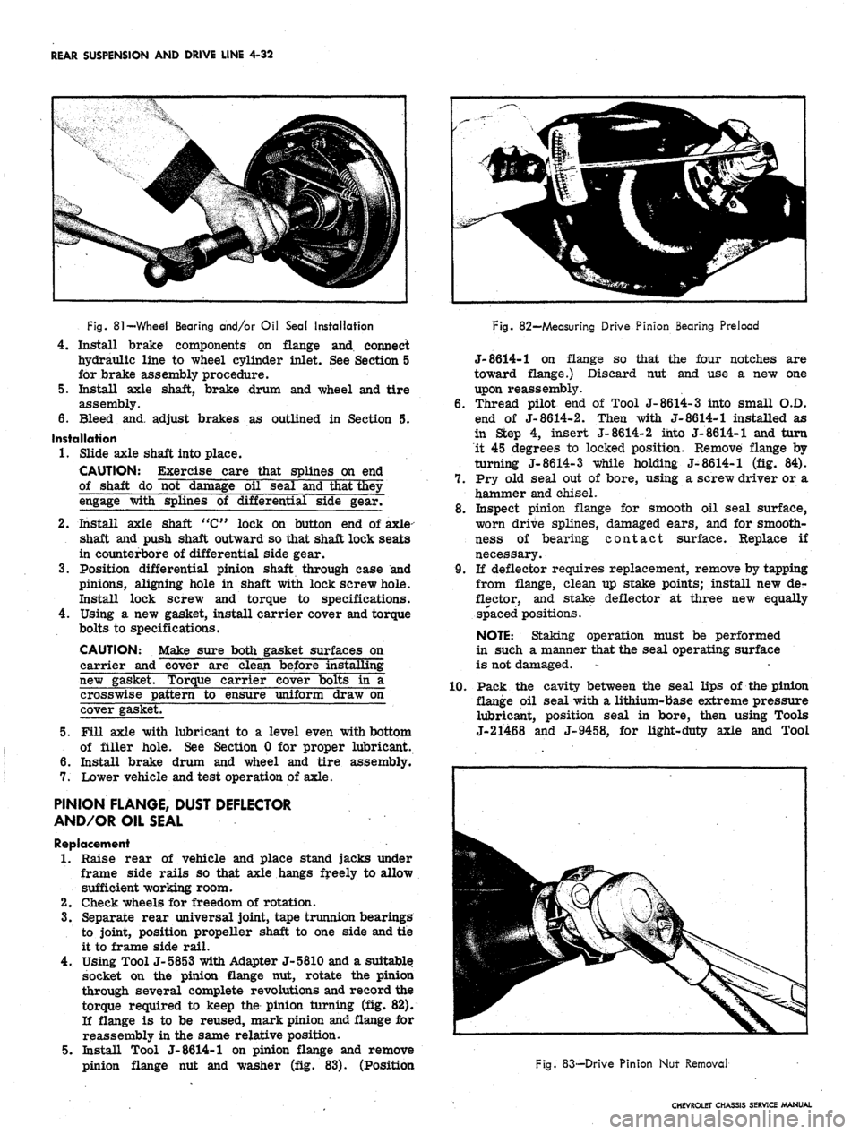
Fig.
81
—Whed Bearing and/or Oil Seal Installation
4.
Install brake components on flange and connect
hydraulic line to wheel cylinder inlet. See Section 5
for brake assembly procedure.
5. Install axle shaft, brake drum and wheel and tire
assembly.
6. Bleed and. adjust brakes as outlined in Section 5.
Installation
1.
Slide axle shaft into place.
CAUTION: Exercise care that splines on end
of shaft do not damage oil seal and that they
engage with splines of differential side gear/
2.
Install axle shaft "C" lock on button end of axle-
shaft and push shaft outward so that shaft lock seats
in counterbore of differential side gear.
3.
Position differential pinion shaft through case and
pinions, aligning hole in shaft with lock screw hole.
Install lock screw and torque to specifications.
4.
Using a new gasket, install carrier cover and torque
bolts to specifications.
CAUTION: Make sure both gasket surfaces on
carrier and cover are clean before installing
new gasket. Torque carrier cover bolts in a
crosswise pattern to ensure uniform draw on
cover gasket.
5. Fill axle with lubricant to a level even with bottom
of filler hole. See Section 0 for proper lubricant.
6. Install brake drum and wheel and tire assembly.
7. Lower vehicle and test operation of axle.
PINION FLANGE, DUST DEFLECTOR
AND/OR OIL SEAL
Replacement
1.
Raise rear of vehicle and place stand jacks under
frame side rails so that axle hangs freely to allow
sufficient working room.
2.
Check wheels for freedom of rotation.
3.
Separate rear universal joint, tape trunnion bearings
to joint, position propeller shaft to one side and tie
it to frame side rail.
4.
Using Tool J-5853 with Adapter J-5810 and a suitable
socket on the pinion flange nut, rotate the pinion
through several complete revolutions and record the
torque required to keep the pinion turning (fig. 82).
If flange is to be reused, mark pinion and flange for
reassembly in the same relative position.
5. Install Tool J-8614-1 on pinion flange and remove
pinion flange nut and washer (fig. 83). (Position
Fig. 82—Measuring Drive Pinion Bearing Preload
J-8614-1 on flange so that the four notches are
toward flange.) Discard nut and use a new one
upon reassembly.
6. Thread pilot end of Tool J-8614-3 into small O.D.
end of J-8614-2. Then with J-8614-1 installed as
in Step 4, insert J-8614-2 into J-8614-1 and turn
it 45 degrees to locked position. Remove flange by
turning J-8614-3 while holding J-8614-1 (fig. 84).
7. Pry old seal out of bore, using a screw driver or a
hammer and chisel.
8. Inspect pinion flange for smooth oil seal surface,
worn drive splines, damaged ears, and for smooth-
ness of bearing contact surface. Replace if
necessary.
9. If deflector requires replacement, remove by tapping
from flange, clean up stake points; install new de-
flector, and stake deflector at three new equally
spaced positions.
NOTE:
Staking operation must be performed
in such a manner that the seal operating surface
is not damaged.
1.0. Pack the cavity between the seal lips of the pinion
flange oil seal with a lithium-base extreme pressure
lubricant, position seal in bore, then using Tools
J-21468 and J-9458, for light-duty axle and Tool
Fig. 83-—Drive Pinion Nut Removal
CHEVROLET CHASSIS SERVICE MANUAL
Page 234 of 659
BRAKES
SECTION 5
CONTENTS OF THIS SECTION
Duo Servo Brakes
Disc Brakes
Page
5-1 Power Brakes
5-24 Special Tools
Page
5-31
5-32
DUO-SERVO BRAKES
INDEX
Page
General Description 5-1
Maintenance and Adjustments 5-3
Hydraulic Brake Fluid .. . 5-3
Bleeding Hydraulic System 5-3
Pressure Bleeding 5-3
Manual Bleeding 5_4
Push Rod to Main Cylinder Clearance 5-5
Hydraulic Brake Lines 5-5
Hydraulic Brake Hose 5-5
Hydraulic Brake Tubing 5-6
Brake Adjustment. .................... 5-7
Service Brake 5-7
Parking Brake 5-8
Component Replacement and Repairs 5-9
Parking Brake - Chevrolet, Chevelle and
Camaro 5^9
Pedal Assembly 5-9
Front Cable ,. . . 5-9
Center Cable 5-9
Rear Cables. . 5-9
Parking Brake - Chevy n 5-9
Lever Assembly 5-9
Idler Lever 5-11
Front Cable 5-11
Rear Cable . . ; 5-12
Parking Brake - Corvette 5-13
Lever Assembly . . . . 5-13
Front Cable 5-14
Rear Cable . . 5-14
Brake Pedal 5-15
Shoes and Linings 5-16
Organic 5-16
Metallic 5-17
Main Cylinder 5-18
Wheel Cylinders 5-21
Anchor Pin 5-22
Front Wheel 5-22
Rear Wheel 5-22
Brake Drums • 5-22
Brake Pipe Distribution and Switch Assembly . . . . . 5-23
Camaro Pressure Regulator Valve 5-23
GENERAL DESCRIPTION
All 1967 models are equipped with a new split brake
system as a safety feature. If a wheel cylinder or brake
line should fail at either the front end or rear end of
the vehicle, the operator can still bring the vehicle to
a controlled stop. The system is designed with separate
hydraulic systems for the front and rear brake using
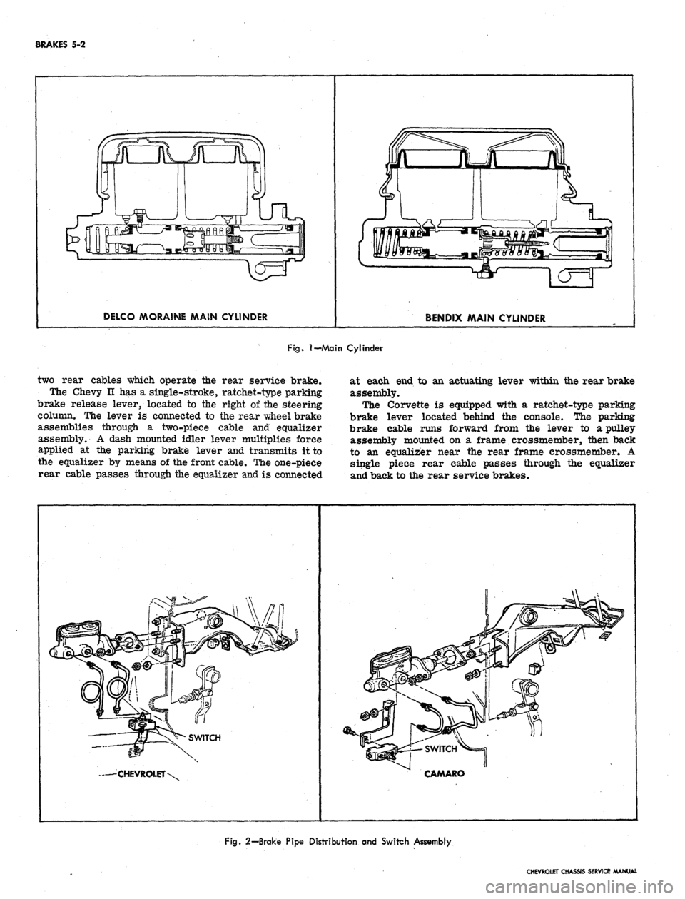
a dual master cylinder (fig. 1). The design of the master
cylinder is similar to that used on the 1966 Corvette
in that it has two entirely separate reservoirs and outlets
in a common body casting. The front reservoir and outlet
is connected to the front wheel brakes, and the rear
reservoir and outlet is connected to the rear wheel
brakes. Two pistons within the master cylinder receive
mechanical pressure from the brake pedal push rod and
transmit it through the brake lines as hydraulic pressure
to the wheel cylinders. The filler cap is accessible from
inside the engine compartment.
A new brake pipe distribution and switch assembly
is mounted below the main cylinder. The front and rear
hydraulic brake lines are routed from the main cylinder,
through the brake pipe distribution and switch assembly,
to the front and rear brakes as shown in Figure 2. The
switch is wired electrically to the brake alarm indicator
light on the instrument panel. In the event of fluid loss
in either the front or rear brake system the indicator
on the instrument panel will illuminate red. (The indi-
cator will also' be illuminated when the parking brake is
applied.)
On Camaro models equipped with air conditioning, the
rear brake hydraulic line is routed through a pressure
regulator valve mounted on the left frame side rail
(fig. 3). The valve controls the hydraulic pressure to
the rear brakes resulting in the correct pressure balance
between the front and rear hydraulic systems.
The self-adjusting brakes (fig. 4), used on both front
and rear of all models, are the Duo-Servo single anchor
type which utilize the momentum of the vehicle to assist
in the brake application. The self-energizing or
self-
actuating force is applied to both brake shoes at each
wheel in both forward and reverse motion. The brake
shoe linings are bonded to the shoes.
Wheel cylinders are the double piston type permitting
even distribution of pressure to each brake shoe. To
keep out dust and moisture, both ejads of each wheel
cylinder are sealed with a rubber booC The wheel
cylinders have no adjustments.
The Chevrolet, Chevelle, and Camaro parking brakes
have a foot operated ratchet type pedal mounted to the
left of the steering column. A cable assembly connects
the pedal to an intermediate cable by means of an equal-
izer, where the adjustment for the parking brake is
incorporated. The intermediate cable attaches to the
CHEVROLET CHASSIS SERVICE MANUAL
Page 235 of 659
BRAKES 5-2
DELCO MORAINE MAIN CYLINDER
BENDIX MAIN CYLINDER
Fig.
I—Main
Cylinder
two rear cables which operate the rear service brake.
The Chevy II has a single-stroke, ratchet-type parking
brake release lever, located to the right of the steering
column. The lever is connected to the rear wheel brake
assemblies through a two-piece cable and equalizer
assembly. A dash mounted idler lever multiplies force
applied at the parking brake lever and transmits it to
the equalizer by means of the front cable. The one-piece
rear cable passes through the equalizer and is connected
at each end to an actuating lever within the rear brake
assembly.
The Corvette is equipped with a ratchet-type parking
brake lever located behind the console. The parking
brake cable runs forward from the lever to a pulley
assembly mounted on a frame crossmember, then back
to an equalizer near the rear frame crossmember. A
single piece rear cable passes through the equalizer
and back to the rear service brakes.
— CHEVROLET
CAMARO
Fig.
2—Brake Pipe Distribution and Switch Assembly
CHEVROLET CHASSIS SERVICE MANUAL