drain bolt CHEVROLET CAMARO 1967 1.G Chassis Owner's Manual
[x] Cancel search | Manufacturer: CHEVROLET, Model Year: 1967, Model line: CAMARO, Model: CHEVROLET CAMARO 1967 1.GPages: 659, PDF Size: 114.24 MB
Page 389 of 659
CLUTCH AND TRANSMISSIONS
7*30
V-8 Models-With Uni-Directional Linkage
1.
Remove air cleaner.
2.
Disconnect accelerator linkage at carburetor.
3.
Disconnect accelerator return and TV rod return
springs.
4.
With right hand, pull TV upper rod forward until
transmission is through detent. With left hand, open
carburetor to wide open throttle position. Carbure-
tor must reach wide open throttle position at the
same time the ball stud contacts end of slot in upper
TV rod.
5. Adjust swivel on end of upper TV rod to obtain set-
ting described in Step 4. Allowable tolerance is
approximately 1/32".
6. Connect and adjust accelerator linkage as described
in Section 6.
7. Check for throttle linkage freedom.
Neutral Safety Switch Adjustment
The adjustment at the neutral safety switch is de-
scribed in the Electrical Section 12.
Throttle Return Check Valve (Dashpot) Adjustment
The adjustment of the throttle return check valve is
described in Section 6M for each carburetor installation.
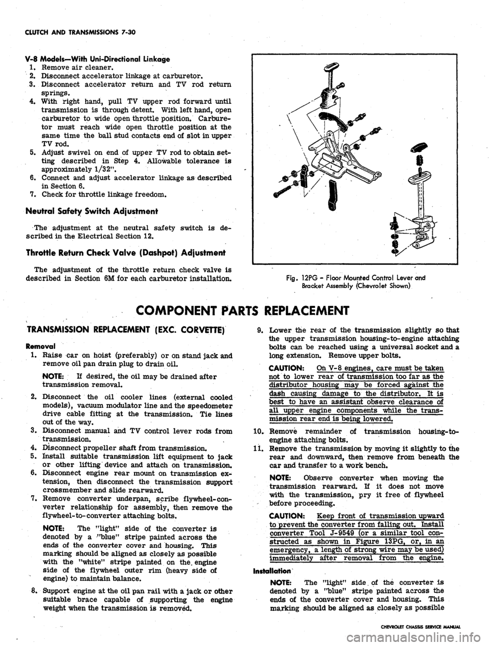
Fig.
12PG - Floor Mounted Control Lever and
Bracket Assembly (Chevrolet Shown)
COMPONENT PARTS REPLACEMENT
TRANSMISSION REPLACEMENT (EXC. CORVETTE)
Removal
1.
Raise car on hoist (preferably) or on stand jack and
remove oil pan drain plug to drain oil.
NOTE:
If desired, the oil may be drained after
transmission removal.
2.
Disconnect the oil cooler lines (external cooled
models), vacuum modulator line and the speedometer
drive cable fitting at the transmission. Tie lines
out of the way.
3.
Disconnect manual and TV control lever rods from
transmission.
4.
Disconnect propeller shaft from transmission.
5. Install suitable transmission lift equipment to jack
or other lifting device and attach on transmission.
6. Disconnect engine rear mount on transmission ex-
tension, then disconnect the transmission support
crossmember and slide rearward.
7. Remove converter underpan, scribe flywheel-con-
verter relationship for assembly, then remove the
flywheel-to-converter attaching bolts.
NOTE:
The "light" side of the converter is
denoted by a "blue" stripe painted across the
ends of the converter cover and housing. This
marking should be aligned as closely as possible
with the "white" stripe painted on the. engine
side of the flywheel outer rim (heavy side of
engine) to maintain balance.
8. Support engine at the oil pan rail with a jack or other
suitable brace capable of supporting the engine
weight when the transmission is removed.
9. Lower the rear of the transmission slightly so that
the upper transmission housing-to-engine attaching
bolts can be reached using a universal socket and a
long extension. Remove upper bolts.
CAUTION: Oh V-8 engines, care must be taken
not to lower rear of transmission too far as the
distributor housing may be forced against the
dash causing damage to the distributor. It is
best to have an assistant observe clearance of
all upper engine components while the trans-
mission rear end is being lowered.
10.
Remove remainder of transmission housing-to-
engine attaching bolts.
11.
Remove the transmission by moving it slightly to the
rear and downward, then remove from beneath the
car and transfer to a work bench.
NOTE:
Observe converter when moving the
transmission rearward. If it does not move
with the transmission, pry it free of flywheel
before proceeding.
CAUTION: Keep front of transmission upward
to prevent the converter from falling out. Install
converter Tool J-9549 (or a similar tool con-
structed as shown in Figure 13PG, or, in an
emergency, a length of strong wire may be used)
immediately after removal from the engine.
Installation
NOTE:
The "light" side, of the converter is
denoted by a "blue" stripe painted across the
ends of the converter cover and housing. This
marking should be aligned as closely as possible
CHEVROLET CHASSIS SERVICE MANUAL
Page 409 of 659
FUEL TANK AND EXHAUST SYSTEMS 8-3
CAUTION: Always drain gasoline from com-
plete fuel system including carburetor, fuel
pump and all fuel lines and fuel tank if the vehi-
cle is to be stored for any appreciable length of
time. This precaution will prevent accumulation
of gum formation and resultant poor engine
performance.
Removal and Installation (Except Station Wagon)
1.
Drain fuel tank.
2.
Raise vehicle.
3.
Disconnect fuel pickup line, ground wire.
4.
Disconnect meter wire at rear harness connector.
5. Disconnect vent pipe hose.
6. Remove tank support straps and lower tank carefully.
7. To install, reverse the removal procedure.
Removal and Installation (Station Wagon)
1.
Drain fuel tank.
2.
Raise vehicle.
3.
Remove gas tank shield at the back of the left rear
wheel; remove all screws including the screw
attachment at the bottom of the quarter panel.
4.
Disconnect fuel pickup line and gauge wires from
tank unit.
5. Remove ground wire attaching bolt at body location.
6. Remove strap assembly nut and carefully lower tank.
7. Reverse removal procedure to install.
FUEL LINES (Fig. 3)
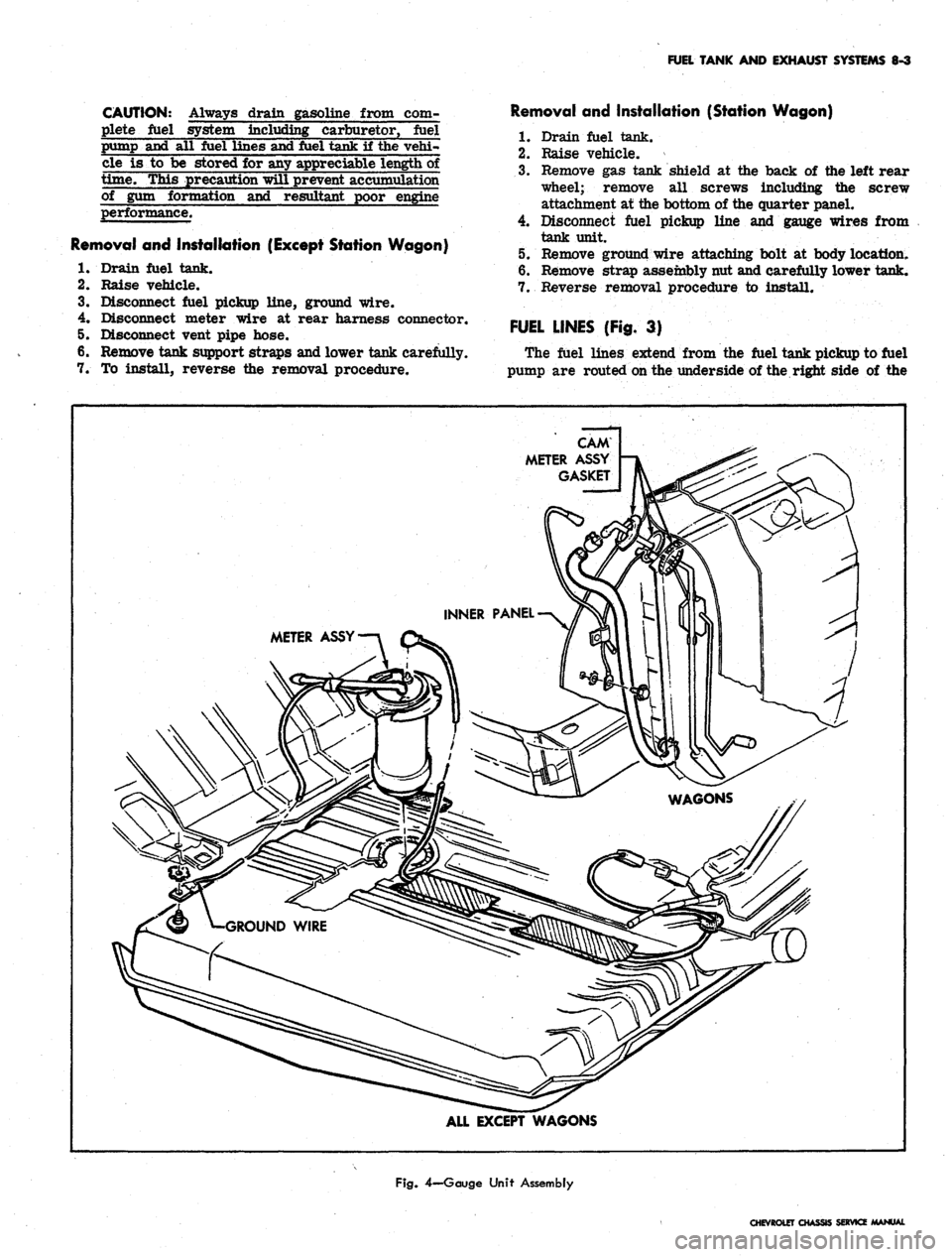
The fuel lines extend from the fuel tank pickup to fuel
pump are routed on the underside of the right side of the
CAM
METER ASSY
GASKET
METER ASSY
ALL EXCEPT WAGONS
Fig.
4—Gauge Unit Assembly
CHEVROLET CHASSIS SERVICE MANUAL
Page 414 of 659
FUEL TANK AND EXHAUST SYSTEMS
8-8
CHEVELLE
FUEL TANKS
INDEX
Page
General Description.
g.g
Component Part Replacement
8-8
Fuel Tanks
. 8-8
Fuel Lines
8-8
Metering Units (Gauge, Sending Unit)
Fuel Tank Filler Neck Caps.
. .
Fuel Tank Vent Lines
Page
8-8
8-8
8-9
GENERAL DESCRIPTION
All models
use a 20
gallon capacity (approx.) fuel tank
mounted between
the
frame rails behind
the
rear axle.
The fuel tanks
are
basically
the
same
for
sedan, 2-seat
station wagon
and
pickup models except
for
filler neck
location
and
venting
(fig. 8).
All fuel tanks
are
vented
to the
atmosphere. Sedan
model tanks have
an
external vent hose and pipe assem-
bly
(fig. 11) and use a
non-vented fuel cap. Station wagon
and pickup model tanks
are
vented through
a
hose
and
vent pipe assembly
to the
filler neck
(fig. 8)
and
use a
vented, anti-surge type
gas cap. The
fuel caps
are two
different designs conforming
to SAE
standards
and are
not interchangeable.
The filler neck assembly
on
sedan models
is a
rear
fill design located behind
the
center
bar of the
bumper.
Station wagon
and
sedan pickup model filler neck assem-
blies
are
located
in
the left rear quarter panel.
The fuel pickup pipe
is
built integrally with
the
tank
gauge, located
at the
top-front center
of
the tank.
A
fine
mesh screen
is
located
at
the bottom-end
of the
fuel pick-
up pipe
to
prevent
the
entrance
of
foreign material into
the fuel system.
The sedan fuel tanks
are
held
in
place
by
two metal
straps attached individually
to the
underbody
at
each
end.
The straps hinge
at the
forward end and secure
the
tank
at
the
rear with
an
adjustable bolt
and nut
assembly.
The station wagon
and
pickup models have
a
frame
mounted fuel tank secured with straps
to
front and rear
supports.
COMPONENT PART REPLACEMENT
FUEL TANK
Draining Tank
The absence
of a
drain plug
in the gas
tanks makes
it
necessary
to
siphon fuel from
the
tank when draining
is
needed. Refer
to the
recommended draining procedures
previously outlined under Chevrolet Models
in
this
section.
Removal
and
Installation (Sedan Models)
1.
Raise vehicle.
2.
Drain fuel tank.
3.
Disconnect fuel pickup line
and
gauge wires from
tank unit.
4.
Disconnect vent hose from tank.
5. Remove tank support straps and lower tank carefully.
6.
To
install, reverse
the
removal procedure.
Removal
and
Installation
(Station Wagon
and
Pickup)
1.
Follow Steps
1
thru
3
outlined under sedan models.
2.
Remove tank support straps.
3.
Remove frame screw attachments from
the
front
support
(fig. 8).
4.
Guide tank forward
and
remove.
5.
To
install, reverse removal procedure.
FUEL LINES
The fuel lines, extending from fuel tank toiiuelpump,
are routed
on the
underside
of the
underbody along
the
right side
of the
vehicle opposite
the
single exhaust
sys-
tem.
The
fuel lines should occasionally
be
inspected
for
leaks,
kinks,
or
dents.
If
evidence
of
dirt
is
found
in the
carburetor
or
fuel pump
on
disassembly,
the
lines should
be disconnected
and
blown
out.
Check
the
fuel tank
strainer
for
damage
or
omission. Fuel lines
are of 5/16"
diameter tubing with beaded type ends
for
connections
of
hoses.
FUEL PIPE RETAINER
CUP
Removal
and
Installation
If fuel pipes
and
retainer clips
are
removed, Tool
J-7777 should
be
used
to
install
new
retainer clips
(fig.
10).
After removal
of the old
clip from
the
frame, position
the
new
clip
in the
location
of the old
clip. Index
the
"blind rivet"
and
press hard (hand pressure should
do)
to expand rivet.
GAUGE UNIT
AND
FUEL STRAINER
Removal
and
Installation
(Fig. 11)
1.
Drain tank
to a
level below
the
unit.
2.
Disconnect fuel pickup line
and
gauge unit wire.
3.
Use
special Tool J-8950
to
remove
cam
lock.
Re-
move unit
and
rubber gasket.
CAUTION: Carefully remove unit
so as not to
damage screen
on the end of
the pipe.
4.
Clean screen
by
blowing
out
with compressed
air.
5. Reverse procedure
to
install.
FUEL TANK FILLER NECK CAPS
The fuel tank filler neck caps
are
non-vented with
an
anti-surge feature. Station wagons have vented caps.
(Refer
to
"Fuel Tank Vent Lines").
CHEVROLET CHASSIS SERVICE MANUAL
Page 419 of 659
FUEL TANK
AND
EXHAUST SYSTEMS
8-13
CHEVY II
FUEL TANKS
INDEX
Page
Page
General Description.
8-13
Component Part Replacement
8-13
Fuel Tanks
8-13
Fuel Lines
8-14
Metering Units (Gauge Sending Unit)
8-13
Fuel Tank Filler- Neck Caps.
. . 8-14
Fuel Tank Vent Lines .......
8-14
GENERAL DESCRIPTION
ANTI-SQUEAK
MA'
ANTI-SQUEAK
MATERIAL
SEDANS
STATION WAGON
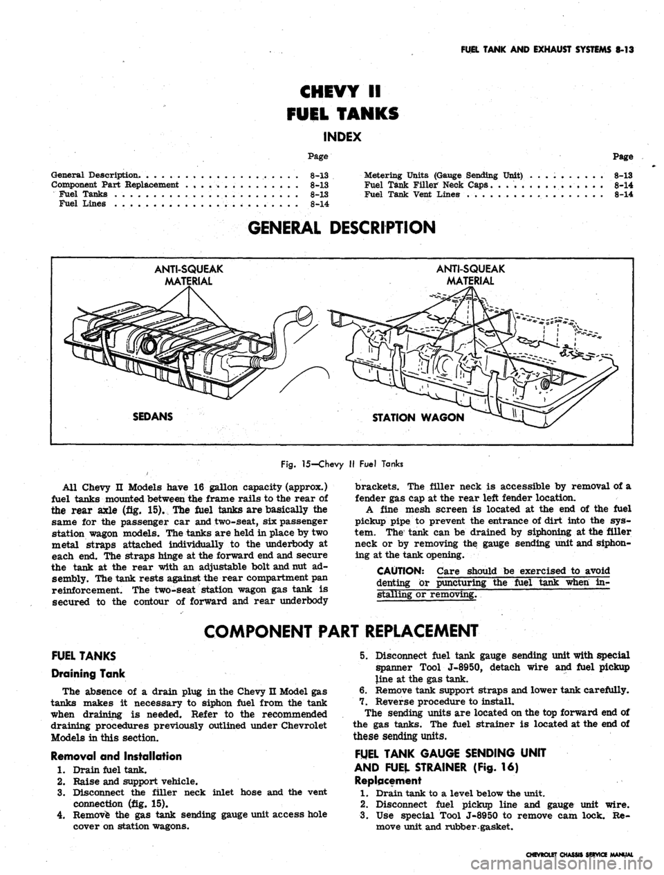
Fig.
15-Chevy
II
Fuel Tanks
All Chevy
II
Models have
16
gallon capacity (approx.)
fuel tanks mounted between
the
frame rails
to the
rear
of
the rear axle
(fig. 15). The
fuel tanks
are
basically
the
same
for the
passenger
car
and two-seat,
six
passenger
station wagon models. The tanks
are
held
in
place
by two
metal straps attached individually
to the
underbody
at
each
end. The
straps hinge
at the
forward
end
and secure
the tank
at the
rear with
an
adjustable bolt and nut
ad-
sembly. The tank rests against the rear compartment
pan
reinforcement.
The
two-seat station wagon
gas
tank
is
secured
to the
contour
of
forward
and
rear underbody
brackets.
The
filler neck
is
accessible
by
removal
of a
fender
gas cap at the
rear left fender location.
A fine mesh screen
is
located
at the end of the
fuel
pickup pipe
to
prevent
the
entrance
of
dirt into
the sys-
tem.
The
tank
can be
drained
by
siphoning
at the
filler
neck
or by
removing
the
gauge sending unit and siphon-
ing
at the
tank opening.
CAUTION: Care should
be
exercised
to
avoid
denting
or
puncturing
the
fuel tank when
in-
stalling
or
removing.
~
COMPONENT PART REPLACEMENT
FUEL TANKS
Draining Tank
The absence
of a
drain plug
in
the Chevy
n
Model
gas
tanks makes
it
necessary
to
siphon fuel from
the
tank
when draining
is
needed. Refer
to the
recommended
draining procedures previously outlined under Chevrolet
Models
in
this section.
Removal
and
Installation
1.
Drain fuel tank.
2.
Raise
and
support vehicle.
3.
Disconnect
the
filler neck inlet hose
and the
vent
connection
(fig. 15).
4.
Remove
the gas
tank sending gauge unit access hole
cover
on
station wagons.
5. Disconnect fuel tank gauge sending unit with special
spanner Tool J-8950, detach wire
and
fuel pickup
line
at the gas
tank.
6. Remove tank support straps and lower tank carefully.
7. Reverse procedure
to
install.
The sending units
are
located on
the top
forward
end of
the
gas
tanks.
The
fuel strainer
is
located
at the end of
these sending units.
FUEL TANK GAUGE SENDING UNIT
AND FUEL STRAINER
(Fig. 16)
Replacement
1.
Drain tank
to a
level below
the
unit.
2.
Disconnect fuel pickup line
and
gauge unit wire.
3.
Use
special Tool J-8950
to
remove
cam
lock.
Re-
move unit and rubber gasket.
CHEVROLET CHASSIS SERVICE MANUAL
Page 424 of 659
FUEL TANK
AND
EXHAUST SYSTEMS
8-18
CORVETTE
FUEL TANK
INDEX
Page
General Description.
. 8-18
Service Operations
8-18
Fuel Tank
8-18
Gauge Sending Unit
8-20
Fuel Lines.
8-20
GENERAL DESCRIPTION
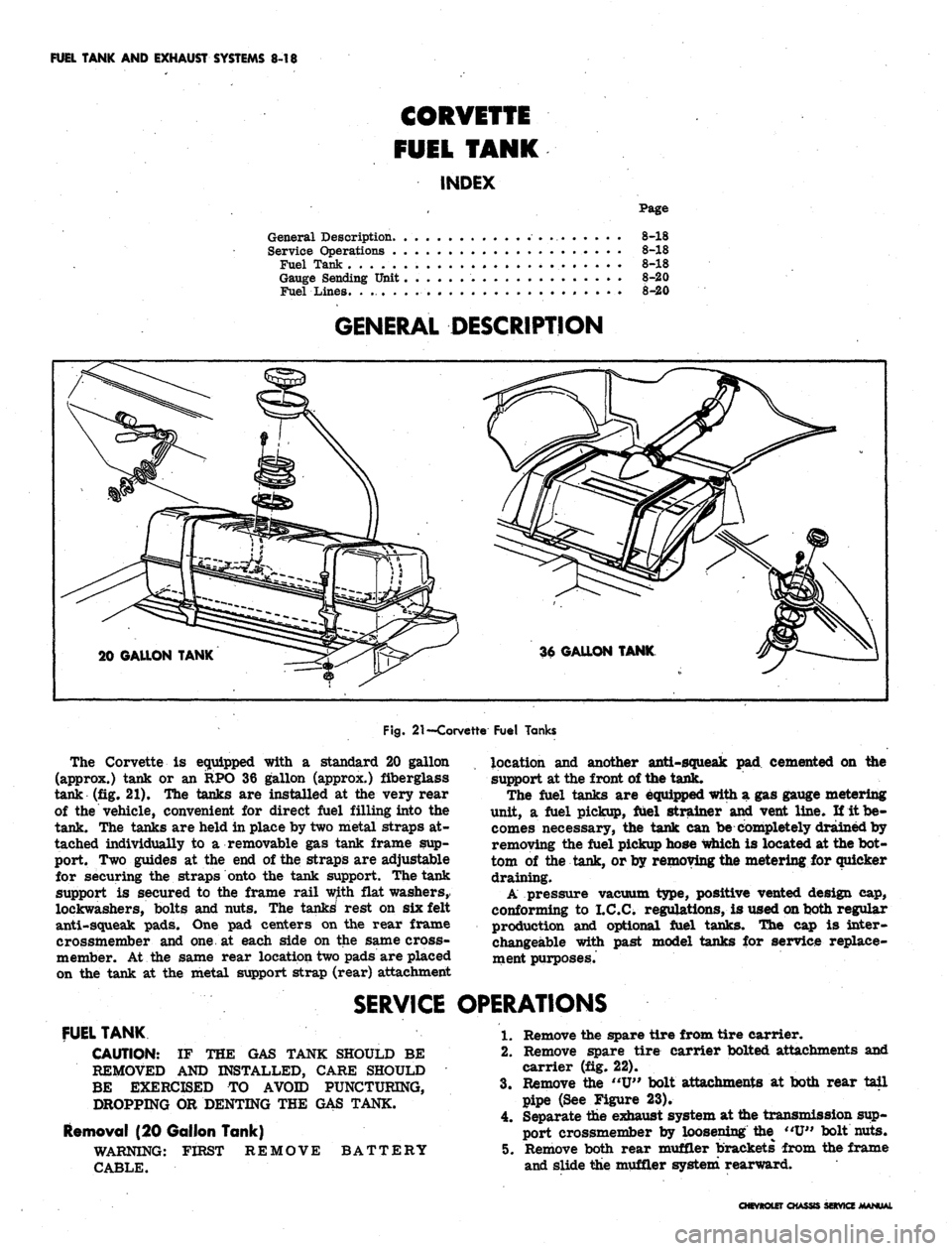
20 GALLON TANK
Fig.
21
—Corvette Fuel Tanks
The Corvette
is
equipped with
a
standard
20
gallon
(approx.) tank
or an RPO 36
gallon (approx.) fiberglass
tank
(fig. 21). The
tanks
are
installed
at the
very rear
of
the
vehicle, convenient
for
direct fuel filling into
the
tank.
The
tanks
are
held
in
place
by
two metal straps
at-
tached individually
to a
removable
gas
tank frame
sup-
port.
Two
guides
at the end of
the straps
are
adjustable
for securing
the
straps onto
the
tank support. The tank
support
is
secured
to the
frame rail with flat washers,
lockwashers, bolts
and
nuts.
The
tanks' rest
on six
felt
anti-squeak pads.
One pad
centers
on the
rear frame
crossmember
and one at
each side
on the
same cross-
member.
At the
same rear location two pads
are
placed
on
the
tank
at the
metal support strap (rear) attachment
location
and
another anti-squeak
pad
cemented
on the
support
at
the front
of
the tank.
The fuel tanks
are
equipped with
a gas
gauge metering
unit,
a
fuel pickup, fuel strainer
and
vent line.
If it be-
comes necessary,
the
tank
can be
completely drained
by
removing
the
fuel pickup hose which
is
located
at
the
bot-
tom
of the
tank,
or
by removing the metering
for
quicker
draining.
A pressure vacuum type, positive vented design
cap,
conforming
to
I.C.C. regulations,
is
used on both regular
production
and
optional fuel tanks.
The cap is
inter-
changeable with past model tanks
for
service replace-
ment purposes.
SERVICE OPERATIONS
FUEL TANK
CAUTION:
IF THE GAS
TANK SHOULD
BE
REMOVED
AND
INSTALLED, CARE SHOULD
BE EXERCISED
TO
AVOID PUNCTURING,
DROPPING
OR
DENTING
THE GAS
TANK.
Removal
(20
Gallon Tank)
WARNING: FIRST REMOVE BATTERY
CABLE.
1.
Remove
the
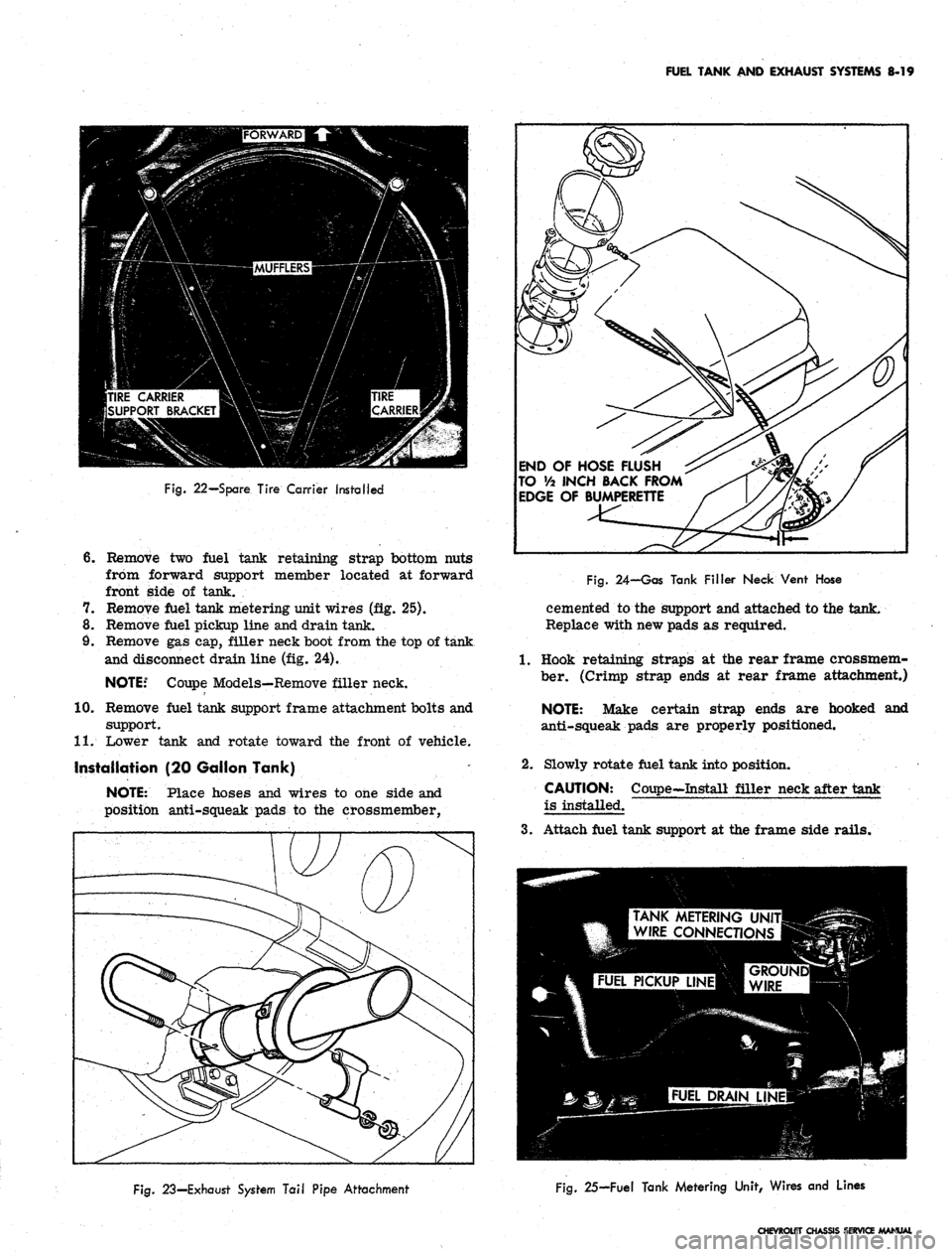
spare tire from tire carrier.
2.
Remove spare tire carrier bolted attachments
and
carrier
(fig. 22).
3.
Remove
the "U"
bolt attachments
at
both rear tail
pipe
(See
Figure
23).
4.
Separate
the
exhaust system
at
the transmission sup-
port crossmember
by
loosening
the "U"
bolt nuts.
5. Remove both rear muffler brackets from
the
frame
and slide
the
muffler system rearward.
CHEVROLET CHASSIS SERVICE MANUAL
Page 425 of 659
FUEL TANK AND EXHAUST SYSTEMS 8-19
Fig.
22—Spare Tire Carrier Installed
6. Remove two fuel tank retaining strap bottom nuts
from forward support member located at forward
front side of tank.
7. Remove fuel tank metering unit wires (fig. 25).
8. Remove fuel pickup line and drain tank.
9. Remove gas cap, filler neck boot from the top of tank
and disconnect drain line (fig. 24).
NOTE:6
Coupe Models—Remove filler neck.
10.
Remove fuel tank support frame attachment bolts and
support.
11.
Lower tank and rotate toward the front of vehicle.
Installation (20 Gallon Tank)
NOTE:
Place hoses and wires to one side and
position anti-squeak pads to the crossmember,
END OF HOSE FLUSH
TO Va INCH BACK FROM
EDGE OF BUMPERETTE
Fig.
24-Gas Tank Filler Neck Vent Hose
cemented to the support and attached to the tank.
Replace with new pads as required.
1.
Hook retaining straps at the rear frame crossmem-
ber. (Crimp strap ends at rear frame attachment.)
NOTE:
Make certain strap ends are hooked and
anti-squeak pads are properly positioned.
2.
Slowly rotate fuel tank into position.
CAUTION: Coupe-Install filler neck after tank
is installed.
3.
Attach fuel tank support at the frame side rails.
TANK METERING UNI
WIRE CONNECTIONS
Fig.
23—Exhaust System Tail Pipe Attachment
Fig.
25—Fuel Tank Metering Unit, Wires and Lines
CHEVROLET CHASSIS SERVICE MANUAL
Page 426 of 659
FUEL TANK AND EXHAUST SYSTEMS 8-20
4.
Attach the retaining straps with strap guide attached
to the fuel tank support, and secure with-the nut and
lockwasher assembly.
5. Connect the filler neck boot to the drain hose of the
tank and install boot around filler neck,
6. Connect the fuel pickup line, ground wire and make
certain that the fuel drain line is flush to 1/2" in-
board of the rear bumper opening.
7. Attach tank metering unit wires (fig. 25).
8. Replace fuel in tank. Replace gas cap.
9. Check for possible leaks.
10.
Reconnect the exhaust system by reversing the above
removal procedures (see "Exhaust System").
11.
Install spare tire carrier by securing the bolt
attachment.
12.
Install the spare tire in the tire carrier.
Removal (36 Gallon Tank)
1.
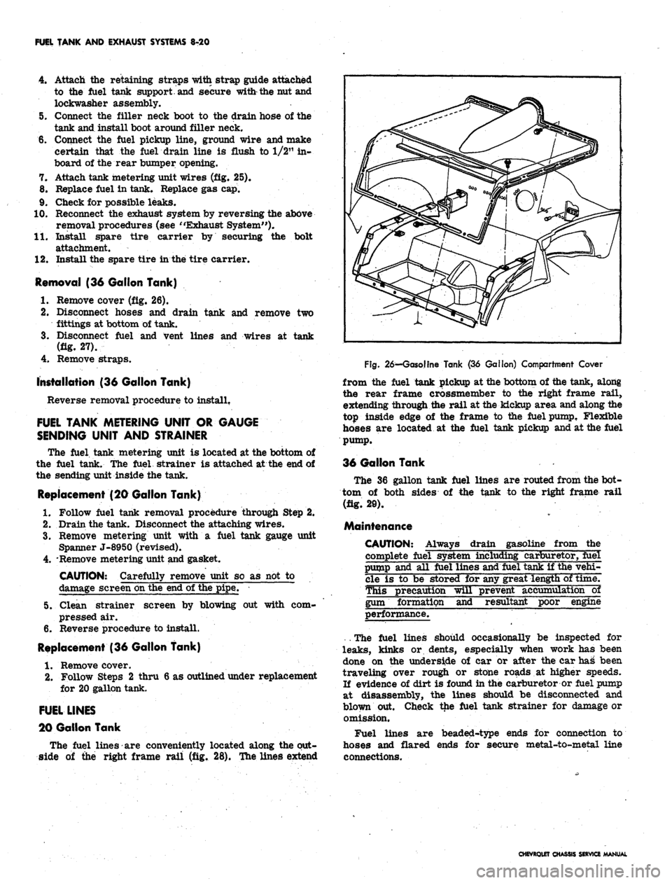
Remove cover (fig. 26).
2.
Disconnect hoses and drain tank and remove two
fittings at bottom of tank.
3.
Disconnect fuel and vent lines and wires at tank
(fig. 27).
4.
Remove straps.
installation (36 Gallon Tank)
Reverse removal procedure to install.
FUEL TANK METERING UNIT OR GAUGE
SENDING UNIT AND STRAINER
The fuel tank metering unit is located at the bottom of
the fuel tank. The fuel strainer is attached at the end of
the sending unit inside the tank.
Replacement (20 Gallon Tank)
1.
Follow fuel tank removal procedure through Step 2.
2.
Drain the tank. Disconnect the attaching wires.
3.
Remove metering unit with a fuel tank gauge unit
Spanner J-8950 (revised).
4.
'Remove metering unit and gasket.
CAUTION: Carefully remove unit so as not to
damage screen on the end of the pipe.
5. Clean strainer screen by blowing out with com-
pressed air.
6. Reverse procedure to install.
Replacement (36 Gallon Tank)
1.
Remove cover.
2.
Follow Steps 2 thru 6 as outlined under replacement
for 20 gallon tank.
FUEL LINES
20 Gallon Tank
The fuel lines are conveniently located along the out-
side of the right frame rail (fig. 28). The lines extend
Fig.
26—Gasoline Tank (36 Gallon) Compartment Cover
from the fuel tank pickup at the bottom of the tank, along
the rear frame crossmember to the right frame rail,
extending through the rail at the kickup area and along the
top inside edge of the frame to the fuel pump, Flexible
hoses are located at the fuel tank pickup and at the fuel
pump.
36 Gallon Tank
The 36 gallon tank fuel lines are routed from the bot-
tom of both sides of the tank to the right frame rail
(fig. 20).
Maintenance
CAUTION: Always drain gasoline from the
complete fuel system including carburetor, fuel
pump and all fuel lines and fuel tank if the vehi-
cle is to be stored for any great length of time.
This precaution will prevent accumulation~ol
gum formation and resultant poor engine
performance.
. The fuel lines should occasionally be inspected for
leaks,
kinks or dents, especially when work has been
done on the underside of car or after the car has been
traveling over rough or stone roads at higher speeds.
If evidence of dirt is found in the carburetor or fuel pump
at disassembly, the lines should be disconnected and
blown put. Check the fuel tank strainer for damage or
omission.
Fuel lines are beaded-type ends for connection to
hoses and flared ends for secure metal-to-metal line
connections.
CHEVROLET CHASSIS SERVICE MANUAL
Page 434 of 659
FUEL TANK AND EXHAUST SYSTEMS 8-28
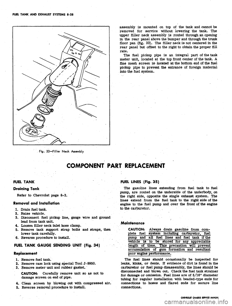
assembly is mounted on top of the tank and cannot be
removed for service without lowering the tank. The
upper filler neck assembly is routed through an opening
in the rear panel above the bumper and through the trunk
floor pan (fig. 33). The filler neck is not centered in the
rear panel but offset to the right to obtain the proper fill
rate.
The fuel pickup pipe is an integral part of the tank
meter unit^ located at the top front center of the tank. A
fine mesh screen is located at the bottom end of the fuel
pickup pipe to prevent the entrance of foreign material
into the fuel system.
Fig.
33—Filler Neck Assembly
COMPONENT PART REPLACEMENT
FUEL TANK
Draining Tank
Refer to Chevrolet page 8-2.
Removal and Installation
1.
Drain fuel tank. .'...' .
2.
Raise vehicle.
3.
Disconnect fuel pickup line, gauge wire and ground
lead from tank unit.
4.
Loosen filler neck inlet hose clamp.
5. Remove tank support strap bolts and straps, then
lower tank carefully.
6. Reverse procedure to install.
FUEL TANK GAUGE SENDING UNIT (Fig. 34)
Replacement
1.
Remove fuel tank.
2.
Remove cam lock using special Tool J-8950.
3.
Remove meter unit and rubber gasket.
CAUTION: Carefully remove unit so as not to
damage screen on end of pipe.
4.
Clean screen by blowing out with compressed air.
5. Reverse removal procedure to install.
FUEL LINES (Fig. 35)
The gasoline lines extending from fuel tank to fuel
pump,
are routed on the underside of the underbody, on
the right side, opposite the single exhaust system. The
lines extend from the fuel tank to the right side of the
engine to the fuel pump and over the front of the engine
to the carburetor.
Maintenance
CAUTION:
plete fuel
Always drain gasoline from corn-
including carburetor, fuel
pump and
fuel lines and fuel tank if the
vehicle is to be stored for any
eciable
length of time. This precaution will prevent
accumulation of gum formation and resultant
poor engine performance.
The fuel lines should occasionally be inspected for
leaks,
kinks, or dents. If evidence of dirt is found in the
carburetor or fuel pump disassembly, the lines should be
disconnected and blown out. Check the fuel tank strainer
for damage or omission. Fuel lines are of 5/16" diameter
tubing for regular installation with beaded-type ends for
connections to hoses and flared ends for secure line
connections.
CHEVROLET CHASSIS SERVICE MANUAL
Page 477 of 659
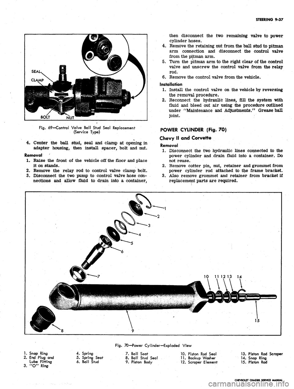
STEERING 9-37
NUT
Fig.
69—Control Valve Ball Stud Seal Replacement
(Service Type)
4.
Center the ball stud, seal and clamp at opening in
adapter housing, then install spacer, bolt and nut.
Removal
1.
Raise the front of the vehicle off the floor and place
it on stands.
2.
Remove the relay rod to control valve clamp bolt.
3.
Disconnect the two pump to control valve hose cdn-
nections and allow fluid to drain into a container,
then disconnect the two remaining valve to power
cylinder hoses.
4.
Remove the retaining nut from the ball stud to pitman
arm connection and disconnect the control valve
from the pitman arm.
5. Turn the pitman arm to the right clear of the control
valve and unscrew the control valve from the relay
rod.
6. Remove the control valve from the vehicle.
Installation
1.
Install the control valve on the vehicle by reversing
the removal procedure.
2.
Reconnect the hydraulic lines, fill the system with
fluid and bleed out air using the procedure outlined
under "Maintenance and Adjustments/' Grease ball
joint.
POWER CYLINDER (Fig. 70)
Chevy II and Corvette
Removal
1.
Disconnect the two hydraulic lines connected to the
power cylinder and drain fluid into a container. Do
not reuse.
2.
Remove cotter pin, nut, retainer and grommet from
power cylinder rod attached to the frame bracket.
3.
Also remove grommet and retainer from bracket if
replacement parts are required.
1.
Snap Ring
2.
End Plug and
Lube Fitting
3.
"O" Ring
Fig.
70—Power Cylinder—Exploded View
4.
Spring
5. Spring Seat
6. Ball Stud
7. Ball Seat
8. Ball Stud Seal
9. Piston Body
10.
Piston Rod Seal
11.
Backup Washer
•12.
Scraper Element
13.
Piston Rod Scraper
14.
Snap Ring
15.
Piston Rod
CHEVROLET CHASSIS SERVICE MANUAL
Page 538 of 659
ELECTRICAL-BODY
AND
CHASSIS
12-26
•
Low oil
pressure
• High engine temperature
• Defective wiring
or
switch
connector from sender
in block above starter
on
and
at
left front
of
distributor
on V-8
Sending Unit Replacement
1.
Disconnect wiring harness
unit terminal (located
L-6 engines
engines).
2.
Remove sender unit using Tool J-21757
or 12
point
socket, replace with
new
unit
and
check operation.
GENERATOR INDICATOR
1.
Ignition
on,
Engine
not
Running
and
Telltale Light
Off.
• Indicator bulb burned out, replace bulb.
• Open circuit
or
loose connection
in the
telltale
light circuit.
2.
telltale Light Stays
on
after Engine
is
Started.
If indicator light does
not go out at
engine idle
speed, refer
to
Charging Systems under Engine
Electrical, Section
6Y.
TEMPERATURE (COOLING SYSTEM) INDICATOR
The temperature indicator circuit consists
of two re-
motely located units, indicator gauge
and
engine sender
unit.
The
indicator gauge, located
in the
instrument
panel, consists
of a
red light which will indicate
an
over-
heated engine condition.
Engine Sender Unit Replacement
1.
Drain engine cooling system
to a
level below unit.
2.
Remove sender unit (located
in the
inlet manifold
near water pump housing
on V-8
engines and
in the
cylinder head near
an
exhaust port
oh L-6
engines)
and replace with new unit.
3.
Refill cooling system
and
check operation
of
unit.
CHEVELLE INSTRUMENTS AND GAUGES
INDEX
Page
General Description
* *
i2-26
Service Operations
12-26
Instrument Panel
12-26
Instrument Cluster.
12-26
Fuel Gauge and/or Ammeter
12-27
Clock,
i 12-27
Speedometer
12-27
Page
Speedometer Cable
.
. 12-27
Temperature Gauge
12-29
Oil Pressure Gauge
12-29
Indicator Lights.
. 12-29
Oil Pressure Indicator
12-29
Generator Indicator
. . 12-29
• Temperature Indicator
12-29
GENERAL DESCRIPTION
The Chevelle instrument cluster assembly consists
of:
a speedometer;
a
fuel gauge;
a
generator,
an
engine
tem-
perature and an
oil
pressure indicator lamp, and includes
a clock
on
deluxe models.
On
super sport models,
am-
meter, coolant temperature
and oil
pressure gauges
re-
place
the
appropriate indicator lights. Except
for the
speedometer,
all of the
indicator lamps, instruments
and
gauges
of
these clusters may
be
serviced without remov-
ing
the
instrument cluster assembly from
the
vehicle.
In addition
to the
instrument indicator lamps,
a
brake
warning lamp
is
included
in the
cluster
as
standard
equipment.
The
indicator
is
connected
to the
parking
brake
and
brake pressure differential switches
and
serves
a
dual function.
It
lights when the parking brake
is applied
and
also when
the
brake pedal
is
applied,
if a
malfunction should occur
in the
brake system
due to a
loss
of
hydraulic pressure. Servicing
of the
hydraulic
pressure differential switch
is
covered
in
Section
5 of
this manual.
Regular maintenance
is not
required on the instrument
cjLuster
or its
components other than maintaining dean
and tight electrical connections, replacing defective parts
and keeping
the
speedometer cable properly lubricated.
SERVICE OPERATIONS
INSTRUMENT PANEL ASSEMBLY
INSTRUMENT CLUSTER (Figs.
41
thru
44)
Removal
1.
Disconnect battery ground cable.
2.
Remove steering coupling bolt and disconnect steer-
ing shaft from coupling.
3.
Loosen mast jacket lower clamp.
4.
Remove
air
conditioning center distributor duct
(if
so equipped).
5. Remove radio rear support bracket screw.
6. Remove mast jacket upper support clamp and retain-
ing bolts from lower support (refer
to
Section
9,
Steering).
CAUTION: Cover mast jacket
and
parl
brake handle with
a
suitable material
to
prevc
scratching.
7.
Disconnect speedometer cable
at
rear
of
cluster
housing
and
speed warning control knob
at
panel
(if
so equipped).
8. Remove instrument panel retaining screws (nine
upper and five lower).
.
9. Working under the console remove four lower retain-
ing screws from instrument cluster housing.
10.
Pull instrument panel assembly from console and
lay
forward on mast jacket.
11.
Disconnect wiring harness, cluster lamps and wiring
CHEVROLET CHASSIS SERVICE MANUAL