engine CHEVROLET CAMARO 1967 1.G Chassis Service Manual
[x] Cancel search | Manufacturer: CHEVROLET, Model Year: 1967, Model line: CAMARO, Model: CHEVROLET CAMARO 1967 1.GPages: 659, PDF Size: 114.24 MB
Page 79 of 659
HEATER AND AIR CONDITIONING 1A-56
BLACK & RED
IGNITION—-y^****
SWITCH -"A
/
BLOWER LEAD—^^^
RESISTOR—-" \^<
ASM.
f'
i
'fu^^^^A^^^^^r"G^OUH£>
WIRE
^^
k4
^EVAPORATOR HARNESS
' EVAPORATOR & BLOWER ASM.
Fig.
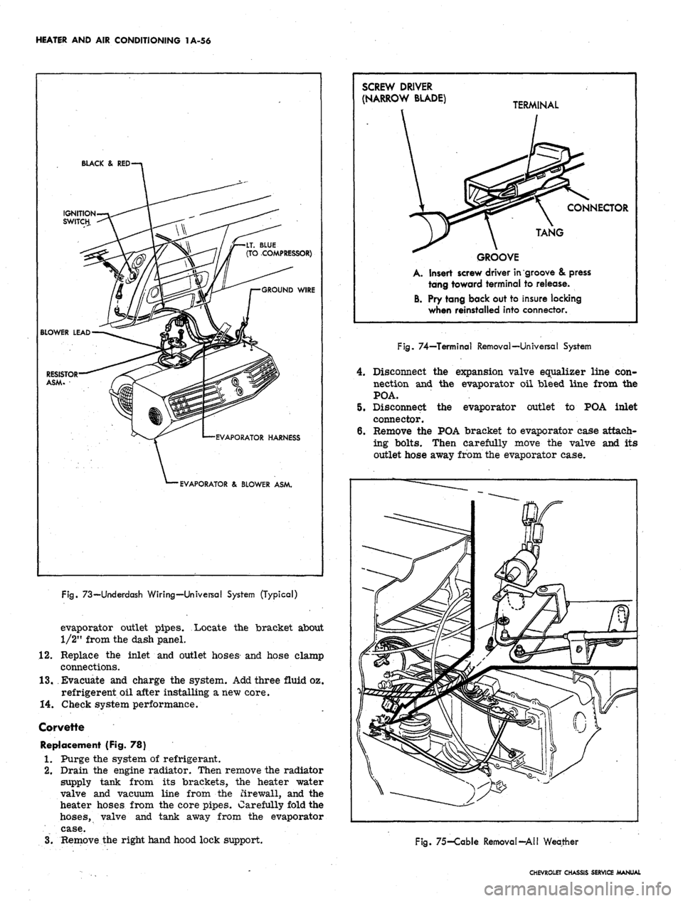
73—Underdash Wiring—Universal System (Typical)
evaporator outlet pipes. Locate the bracket about
1/2" from the dash panel.
12.
Replace the inlet and outlet hoses and hose clamp
connections.
13.
Evacuate and charge the system. Add three fluid oz.
refrigerent oil after installing a new core.
14.
Check system performance.
Corvette
Replacement (Fig. 78)
1.
Purge the system of refrigerant.
2.
Drain the engine radiator. Then remove the radiator
supply tank from its brackets, the heater water
valve and vacuum line from the firewall, and the
heater hoses from the core pipes. Carefully fold the
hoses,
valve and tank away from the evaporator
case.
3.
Remove the right hand hood lock support.
SCREW DRIVER
(NARROW BLADE) T£
GROOVE
A. Insert screw driver in
tang toward terminal
B. Pry tang back out to
when reinstalled into
RMINAL
\ CONNECTOR
TANG
groove & press
to release.
insure locking
connector.
Fig.
74—Terminal Removal—Universal System
4.
Disconnect the expansion valve equalizer line con-
nection and the evaporator oil bleed line from the
POA.
5.
Disconnect the evaporator outlet to POA inlet
connector.
6. Remove the POA bracket to evaporator case attach-
ing bolts. Then carefully move the valve and its
outlet hose away from the evaporator case.
Fig.
75-Cable Removal-All Weather
CHEVROLET CHASSIS SERVICE MANUAL
Page 85 of 659
HEATER AND AIR CONDITIONING 1A-62
2.
Insert the evaporator assembly into the outlet case
half and mount the evaporator, thermostatic switch,
and cable to the case.
3.
Install the face plate to the case and install control
retaining nuts and knobs.
4.
Assemble the case halves and mount the evaporator
pipe clamp.
5. Install the evaporator assembly as previously
described under EVAPORATOR.
BLOWER ASSEMBLY
Four-Season System
Chevrolet and Camaro
Removal
1.
Disconnect battery ground cable.
2.
Remove the right front fender and skirt assembly.
3.
Disconnect the motor wire at the flange connector.
4.
Disconnect the rubber air cooling tube from the
motor.
5. Remove the motor to case attaching screws and re-
move the blower assembly. If the sealer acts as an
adhesive, pry the assembly carefully away from the
6. Remove the blower from the motor shaft.
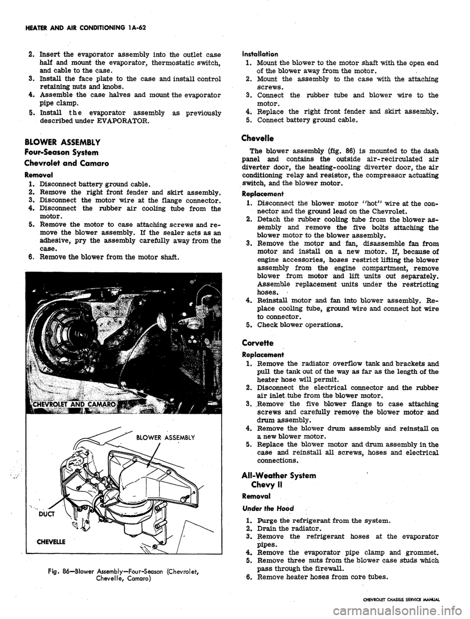
Fig.
86—Blower Assembly—Four-Season (Chevrolet,
Chevelle, Camaro)
Installation
1.
Mount the blower to the motor shaft with the open end
of the blower away from the motor.
2.
Mount the assembly to the case with the attaching
screws.
3.
Connect the rubber tube and blower wire to the
motor.
4.
Replace the right front fender and skirt assembly.
5. Connect battery ground cable.
Chevelle
The blower assembly (fig. 86) is mounted to the dash
panel and contains the outside air-recirculated air
diverter door, the heating-cooling diverter door, the air
conditioning relay and resistor, the compressor actuating
switch, and the blower motor.
Replacement
1.
Disconnect the blower motor "hot" wire at the con-
nector and the ground lead on the Chevrolet.
2.
Detach the rubber cooling tube from the blower as-
sembly and remove the five bolts attaching the
blower motor to the blower assembly.
3.
Remove the motor and fan, disassemble fan from
motor and install on a new motor. If, because of
engine accessories, hoses restrict lifting the blower
assembly from the engine compartment, remove
blower from motor and lift units out separately.
Assemble replacement units under the restricting
hoses.
4.
Reinstall motor and fan into blower assembly. Re-
place cooling tube, ground wire and connect hot wire
to connector.
5. Check blower operations.
Corvette
Replacement
1.
Remove the radiator overflow tank and brackets and
pull the tank out of the way as far as the length of the
heater hose will permit.
2.
Disconnect the electrical connector and the rubber
air inlet tube from the blower motor.
3.
Remove the five blower flange to case attaching
screws and carefully remove the blower motor and
drum assembly.
4.
Remove the blower drum assembly and reinstall on
a new blower motor.
5. Replace the blower motor and drum assembly in the
case and reinstall all screws, hoses and electrical
connections.
All-Weather System
Chevy II
Removal
Under the Hood
1.
Purge the refrigerant from the system.
2.
Drain the radiator.
3.
Remove the refrigerant hoses at the evaporator
pipes.
4.
Remove the evaporator pipe clamp and grommet.
5. Remove three nuts from the blower case studs which
pass through the firewall.
6. Remove heater hoses from core tubes.
CHEVROLET CHASSIS SERVICE MANUAL
Page 86 of 659
HEATER AND AIR CONDITIONING 1A-63
Under Dash
7. Remove ash tray and retainer, and glove box.
8. Remove blower case to air inlet adapter bracket
retaining screw.
9. Remove screw attaching air distributor to firewall.
10.
Remove nuts retaining evaporator case to lower lip
of dash. Withdraw evaporator drain tubes.
11.
Lower complete heater - air conditioning assembly.
12.
Remove screw retaining blower case to air distrib-
utor and separate them.
13.
Remove blower to case attaching screws. Disconnect
motor wire and remove blower assembly.
14.
Remove blower from motor shaft.
Installation
1.
Assemble blower to motor shaft.
2.
Mount motor in blower case and connect wire.
3.
Assemble blower case to air distributor and install
retaining screw.
4.
Lift the complete assembly into place and install
attaching screws and nuts.
5. Replace ash tray retainer and tray and glove box.
6. Replace nuts (engine side of dash) on heater case
studs and connect heater hoses.
7. Replace evaporator pipe clamp and grommet.
8. Replace the refrigerant hoses.
9. Evacuate and charge the refrigeration system and
refill the cooling system.
10.
Check system performance.
Universal Blower Assembly
Removal
1.
Remove the universal unit from its dash mounts.
2.
Remove the cover plate and separate the upper and
lower case halves. Remove blower motor mounting
strap screw and swing strap outward.
3.
Remove blower assembly. Loosen the blower wheel
setscrews and remove the wheels from the motor
shaft. . ' .
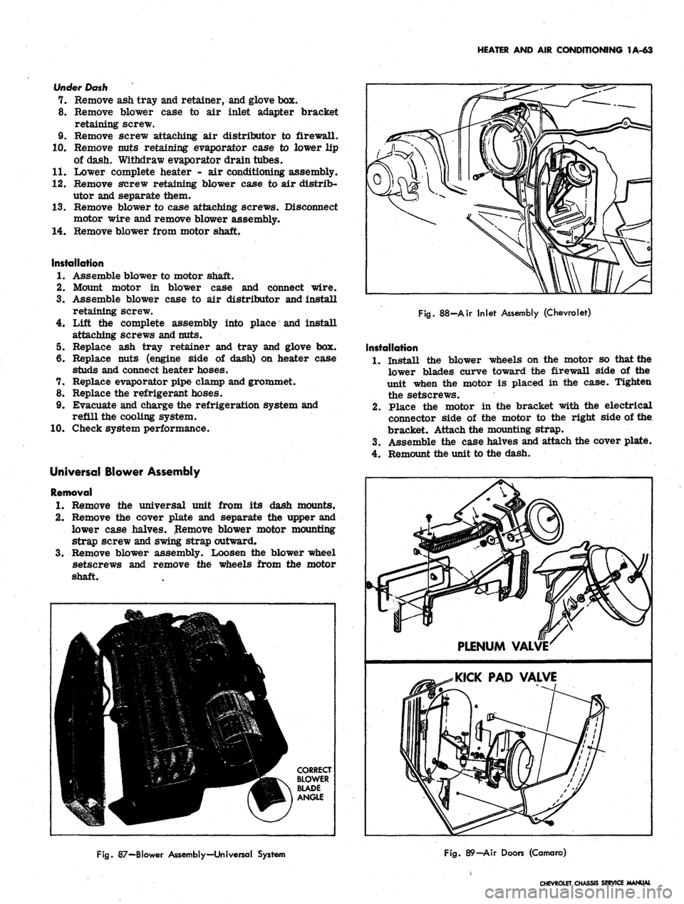
Fig.
88-Air Inlet Assembly (Chevrolet)
Installation
1.
Install the blower wheels on the motor so that the
lower blades curve toward the firewall side of the
unit when the motor is placed in the case. Tighten
the setscrews.
2.
Place the motor in the bracket with the electrical
connector side of the motor to the right side of the
bracket. Attach the mounting strap.
3.
Assemble the case halves and attach the cover plate.
4.
Remount the unit to the dash.
Fig.
87—Blower Assembly—Universal System
Fig.
89—Air Doors (Camaro)
CHEVROLET CHASSIS SERVICE
Page 87 of 659
HEATER AND AIR CONDITIONING 1A-64
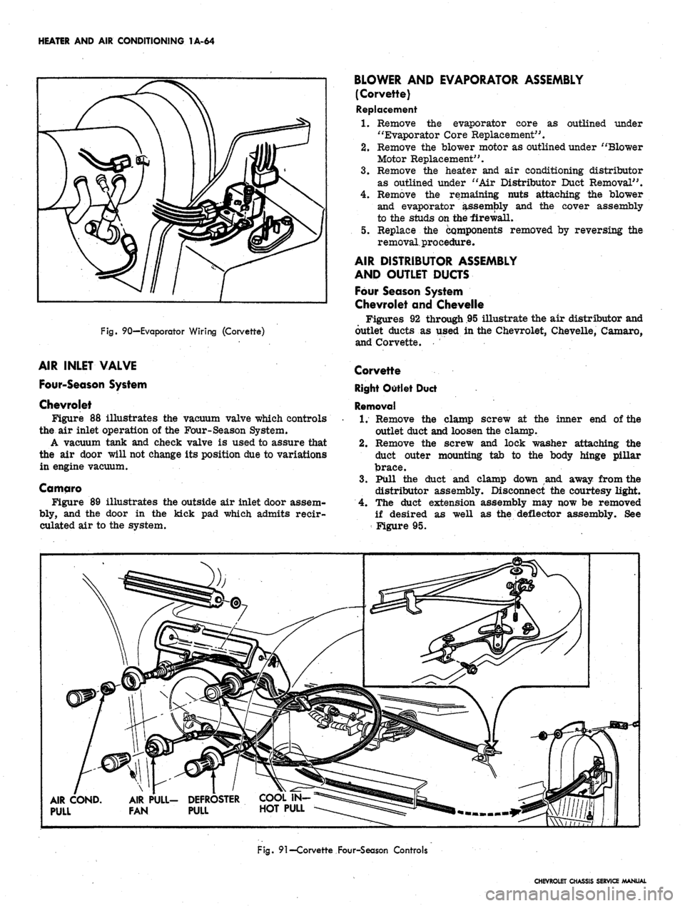
Fig.
90—Evaporator Wiring (Corvette)
AIR INLET VALVE
Four-Season System
Chevrolet
Figure 88 illustrates the vacuum valve which controls
the air inlet operation of the Four-Season System.
A vacuum tank and check valve is used to assure that
the air door will not change its position due to variations
in engine vacuum.
Camqro
Figure 89 illustrates the outside air inlet door assem-
bly, and the door in the kick pad which admits reeir-
culated air to the system.
BLOWER AND EVAPORATOR ASSEMBLY
(Corvette)
Replacement
1.
Remove the evaporator core as outlined under
"Evaporator Core Replacement".
2.
Remove the blower motor as outlined under "Blower
Motor Replacement".
3.
Remove the heater and air conditioning distributor
as outlined under "Air Distributor Duct Removal".
4.
Remove the remaining nuts attaching the blower
and evaporator assembly and the cover assembly
to the studs on the -firewall.
5. Replace the components removed by reversing the
removal, procedure.
AIR DISTRIBUTOR ASSEMBLY
AND OUTLET DUCTS
Four Season System
Chevrolet and Chevelle
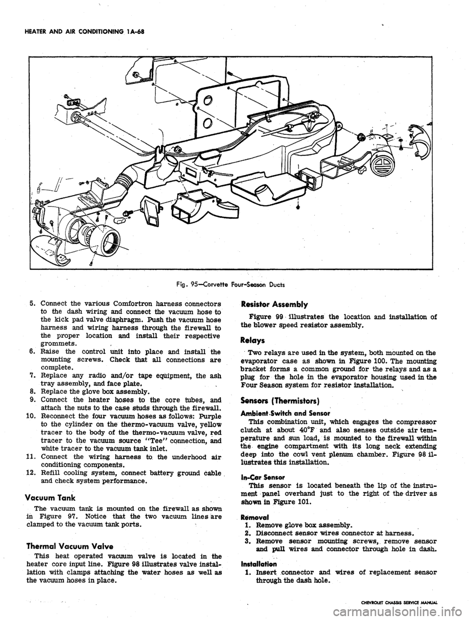
Figures 92 through .95 illustrate the air distributor and
outlet ducts as used in the Chevrolet, Chevelle, Camaro,
and Corvette.
Corvette
Right Outlet Duct
Removal
1.
Remove the clamp screw at the inner end of the
outlet duct and loosen the clamp.
2.
Remove the screw and lock washer attaching the
duct outer mounting tab to the body hinge pillar
brace.
3.
Pull the duct and clamp down and away from the
distributor assembly. Disconnect the courtesy light.
4.
The duct extension assembly may now be removed
if desired as well as the deflector assembly. See
Figure 95.
AIR COND.
PULL
AIR PULL- DEFROSTER
FAN PULL HOT PULL
Fig.
91—Corvette Four-Season Controls
CHEVROLET CHASSIS SERVICE MANUAL
Page 90 of 659
HEATER AND AIR CONDITIONING 1A-67
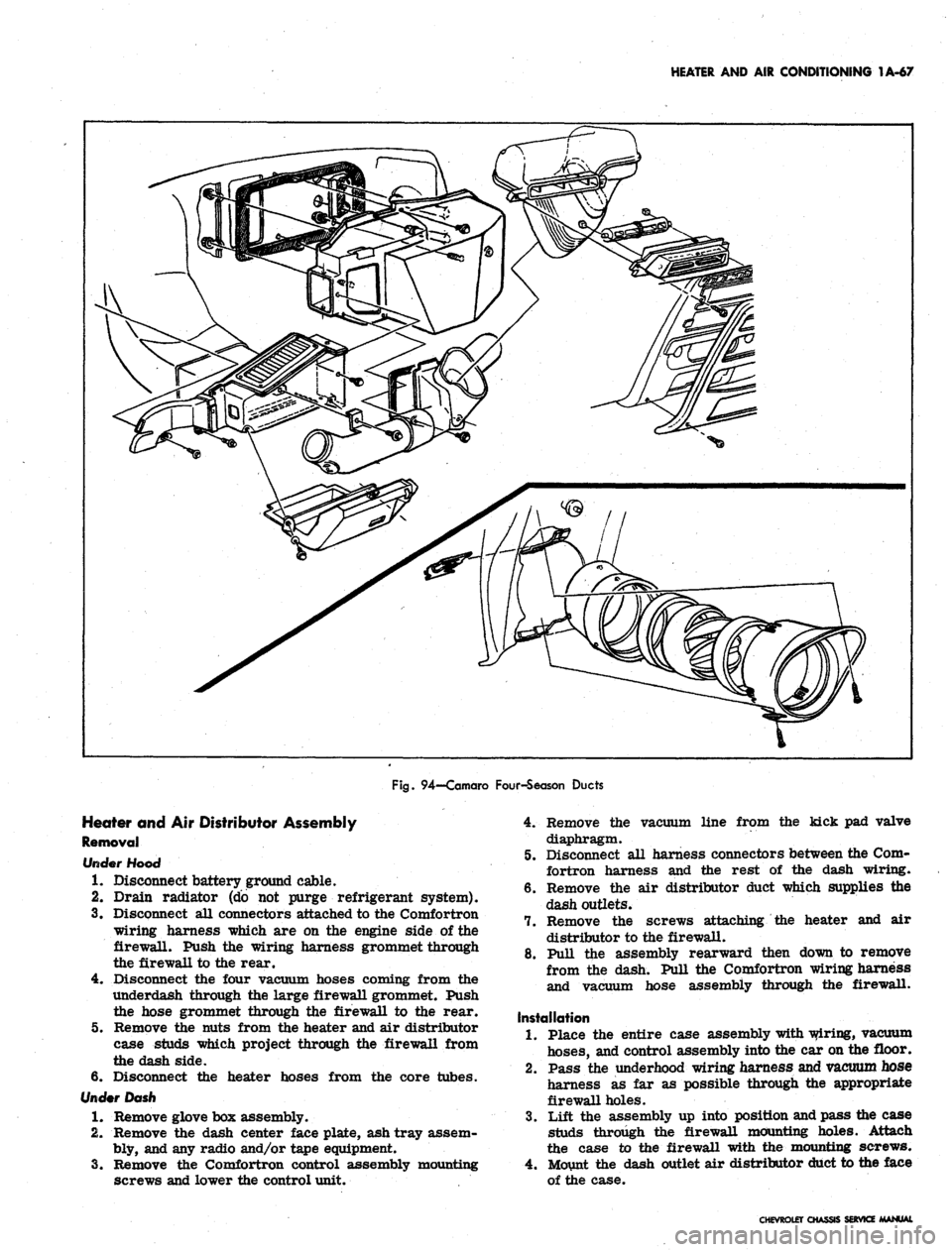
Fig.
94—Camaro Four-Season Ducts
Heater and Air Distributor Assembly
Removal
rfooo
1.
Disconnect battery ground cable.
2.
Drain radiator (do not purge refrigerant system).
3.
Disconnect all connectors attached to the Comfortron
wiring harness which are on the engine side of the
firewall. Push the wiring harness grommet through
the firewall to the rear.
4.
Disconnect the four vacuum hoses coming from the
underdash through the large firewall grommet. Push
the hose grommet through the firewall to the rear.
5.
Remove the nuts from the heater and air distributor
case studs which project through the firewall from
the dash side.
6. Disconnect the heater hoses from the core tubes.
Under Dash
1.
Remove glove box assembly.
2.
Remove the dash center face plate, ash tray assem-
bly, and any radio and/or tape equipment.
3.
Remove the Comfortron control assembly mounting
screws and lower the control unit.
4.
Remove the vacuum line from the kick pad valve
diaphragm.
5.
Disconnect all harness connectors between the Com-
fortron harness and the rest of the dash wiring.
6. Remove the air distributor duct which supplies the
dash outlets.
7.
Remove the screws attaching the heater and air
distributor to the firewall.
8. Pull the assembly rearward then down to remove
from the dash. Pull the Comfortron wiring harness
and vacuum hose assembly through the firewall.
Installation
1.
Place the entire case assembly with wiring, vacuum
hoses,
and control assembly into the car on the floor.
2.
Pass the underhood wiring harness and vacuum hose
harness as far as possible through the appropriate
firewall holes.
3.
Lift the assembly up into position and pass the case
studs through the firewall mounting holes. Attach
the case to the firewall with the mounting screws.
4.
Mount the dash outlet air distributor duct to the face
of the case.
CHEVROLET CHASSIS SERVICE MANUAL
Page 91 of 659
HEATER AND AIR CONDITIONING 1A-68
Fig.
95—Corvette Four-Season Ducts
5. Connect the various Comfortron harness connectors
to the dash wiring and connect the vacuum hose to
the kick pad valve diaphragm. Push the vacuum hose
harness and wiring harness through the firewall to
the proper location and install their respective
grommets.
6. Raise the control unit into place and install the
mounting screws. Check that all connections are
complete.
7. Replace any radio and/or tape equipment, the ash
tray assembly, and face plate.
8. Replace the glove box assembly.
9. Connect the heater hoses to the core tubes, and
attach the nuts to the case studs through the firewall.
10.
Reconnect the four vacuum hoses as follows: Purple
to the cylinder on the thermo-vacuum valve, yellow
tracer to the body of the thermo-vacuum valve, red
tracer to the vacuum source "Tee" connection, and
white tracer to the vacuum tank inlet.
11.
Connect the wiring harness to the underhood air
conditioning components.
12.
Refill cooling system, connect battery ground cable
and check system performance.
Vacuum Tank
The vacuum tank is mounted on the firewall as shown
in Figure 97. Notice that the two vacuum lines are
clamped to the vacuum tank ports. *
Thermal Vacuum Valve
This heat operated vacuum valve is located in the
heater core input line. Figure 98 illustrates valve instal-
lation with clamps attaching the water hoses as well as
the vacuum hoses in place.
Resistor Assembly
Figure 99 illustrates the location and installation of
the blower speed resistor assembly.
Relays
Two relays are used in the system, both mounted on the
evaporator case as shown in Figure 100. The mounting
bracket forms a common ground for the relays and as a
plug for the hole in the evaporator housing used in the
Four Season system for resistor installation.
Sensors (Thermistors)
Ambient Switch and Sensor
This combination unit, which engages the compressor
clutch at about 40°F and also senses outside air tem-
perature and sun load, is mounted to the firewall within
the engine compartment with its long neck extending
deep into the cowl vent plenum chamber. Figure 98 il-
lustrates this installation,
In-Car Sensor
This sensor is located beneath the lip of the instru-
ment panel overhand just to the right of the driver as
shown in Figure 101.
Removal
1.
Remove glove box assembly.
2.
Disconnect sensor wires connector at harness.
3.
Remove sensor mounting screws, remove sensor
and pull wires and connector through hole in dash.
Installation
1.
Insert connector and
through the dash hole.
wires of replacement sensor
CHEVROLET CHASSIS SERVICE MANUAL
Page 92 of 659
HEATER AND AIR CONDITIONING 1A-69
Fig.
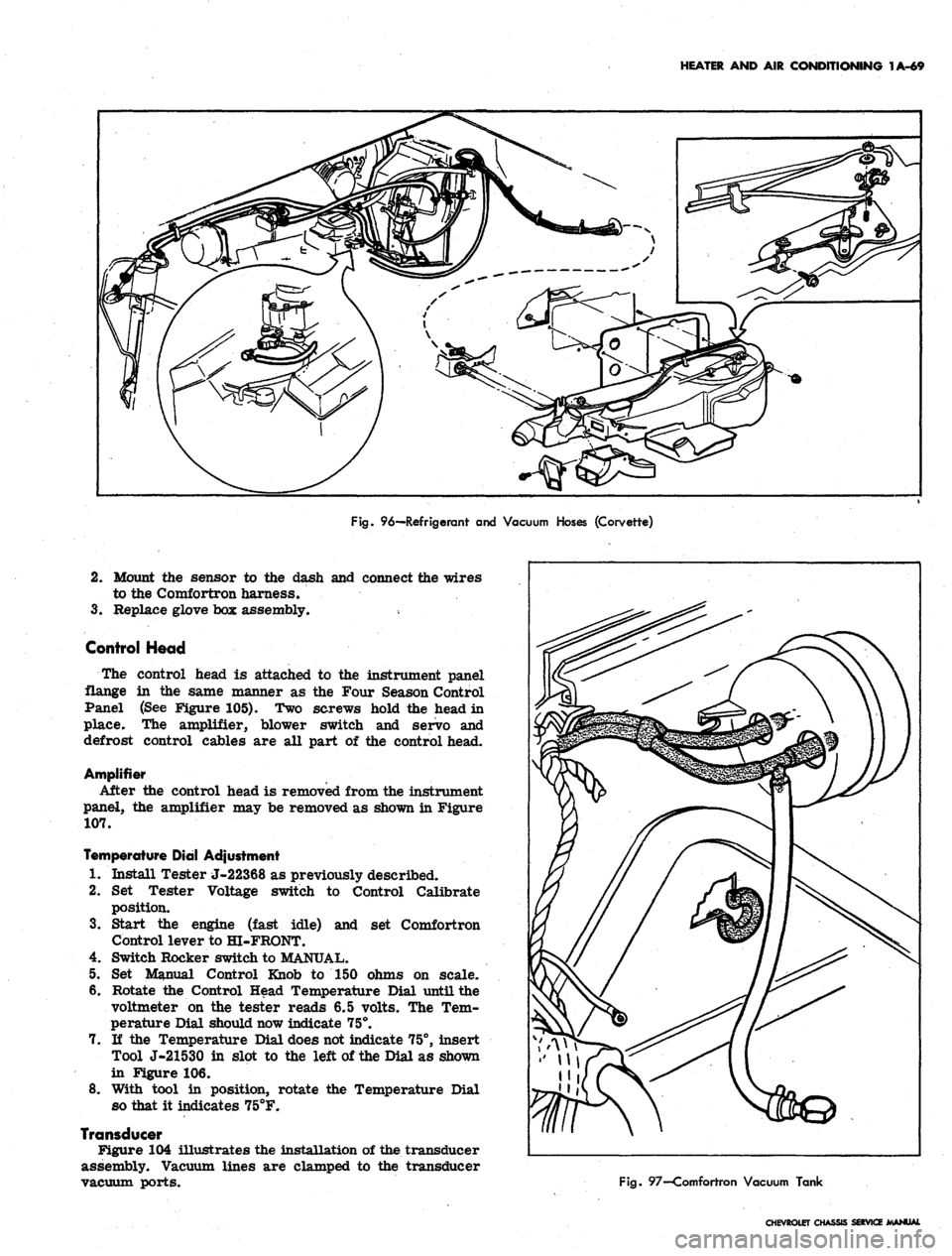
96—Refrigerant and Vacuum Hoses (Corvette)
2.
Mount the sensor to the dash and connect the wires
to the Comfortron harness.
3.
Replace glove box assembly.
Control Head
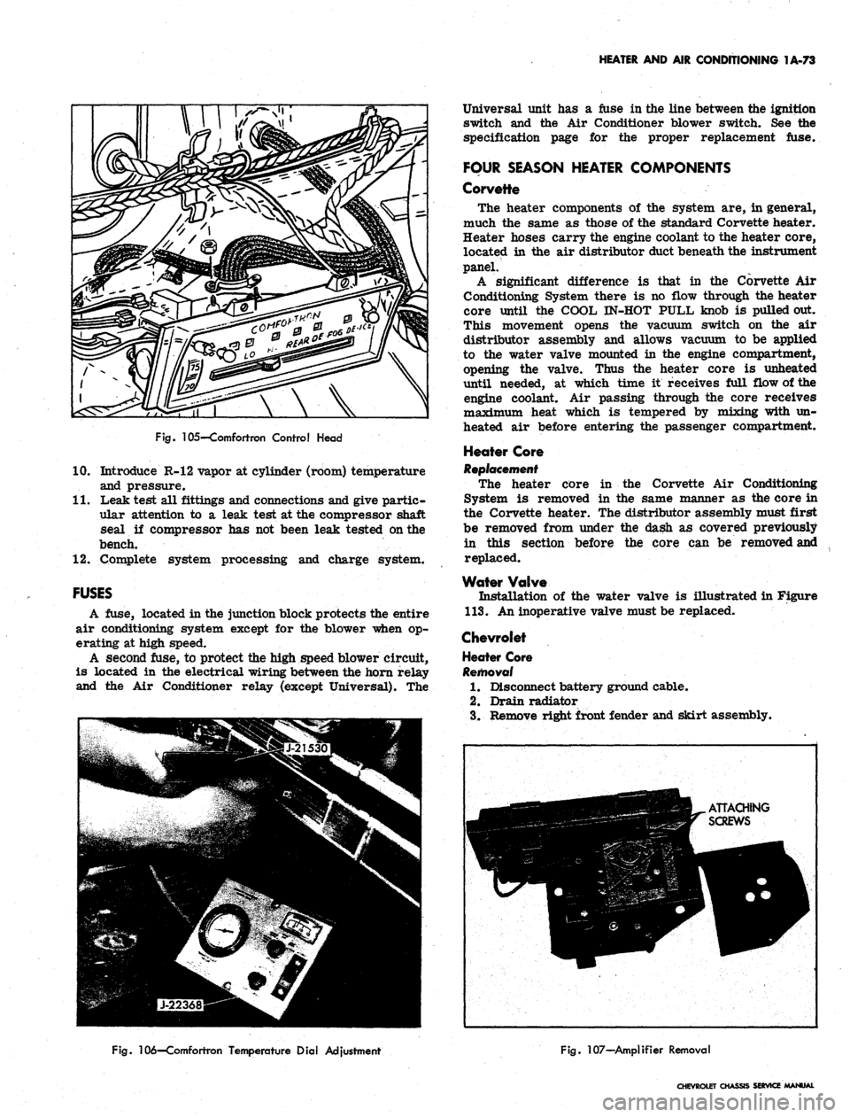
The control head is attached to the instrument panel
flange in the same manner as the Four Season Control
Panel (See Figure 105). Two screws hold the head in
place. The amplifier, blower switch and servo and
defrost control cables are all part of the control head.
Amplifier
After the control head is removed from the instrument
panel, the amplifier may be removed as shown in Figure
107.
Temperature Dial Adjustment
1.
Install Tester J-22368 as previously described.
2.
Set Tester Voltage switch to Control Calibrate
position.
3.
Start the engine (fast idle) and set Comfortron
Control lever to HI-FRONT.
4.
Switch Rocker switch to MANUAL.
5. Set Manual Control Knob to 150 ohms on scale.
6. Rotate the Control Head Temperature Dial until the
voltmeter on the tester reads 6.5 volts. The Tem-
perature Dial should now indicate 75°.
7. If the Temperature Dial does not indicate 75°, insert
Tool J-21530 in slot to the left of the Dial as shown
in Figure 106.
8. With tool in position, rotate the Temperature Dial
so that it indicates 75°F.
Transducer
Figure 104 illustrates the installation of the transducer
assembly. Vacuum lines are clamped to the transducer
vacuum ports.
Fig.
97—Comfortron Vacuum Tank
CHEVROLET CHASSIS SERVICE JWANUAl
Page 96 of 659
HEATER AND AIR CONDITIONING 1A-73
Fig.
105—Comfortron Control Head
10.
Introduce R-12 vapor at cylinder (room) temperature
and pressure.
11.
Leak test all fittings and connections and give partic-
ular attention to a leak test at the compressor shaft
seal if compressor has not been leak tested on the
bench.
12.
Complete system processing and charge system.
FUSES
A fuse, located in the junction block protects the entire
air conditioning system except for the blower when op-
erating at high speed.
A second fuse, to protect the high speed blower circuit,
is located in the electrical wiring between the horn relay
and the Air Conditioner relay (except Universal). The
Universal unit has a fuse in the line between the ignition
switch and the Air Conditioner blower switch. See the
specification page for the proper replacement fuse.
FOUR SEASON HEATER COMPONENTS
Corvette
The heater components of the system are, in general,
much the same as those of the standard Corvette heater.
Heater hoses carry the engine coolant to the heater core,
located in the air distributor duct beneath the instrument
panel.
A significant difference is that in the Corvette Air
Conditioning System there is no flow through the heater
core until the COOL IN-HOT PULL knob is pulled out.
This movement opens the vacuum switch on the air
distributor assembly and allows vacuum to be applied
to the water valve mounted in the engine compartment,
opening the valve. Thus the heater core is unheated
until needed, at which time it receives full flow of the
engine coolant. Air passing through the core receives
maximum heat which is tempered by mixing with un-
heated air before entering the passenger compartment.
Heater Core
Replacement
The heater core in the Corvette Air Conditioning
System is removed in the same manner as the core in
the Corvette heater. The distributor assembly must first
be removed from under the dash as covered previously
in this section before the core can be removed and
replaced.
Water Valve
Installation of the water valve is illustrated in Figure
113.
An inoperative valve must be replaced.
Chevrolet
Heater Core
Removal
1.
Disconnect battery ground cable.
2.
Drain radiator
3.
Remove right front fender and skirt assembly.
Fig.
106—Comfortron Temperature Dial Adjustment
Fig.
107—Amplifier Removal
CHEVROLET CHASSIS SERVICE MANUAL
Page 97 of 659
HEATER AND AIR CONDITIONING 1A-74
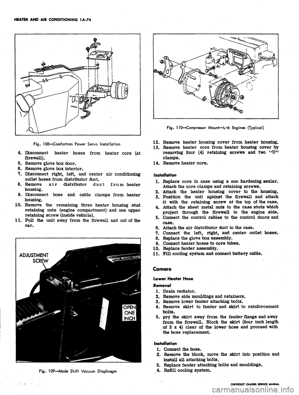
Fig.
108—Comfortron Power Servo Installation
4.
Disconnect heater' hoses from heater core (at
firewall).
5. Remove glove box door.
6. Remove glove box interior.
7. Disconnect right, left, and center air conditioning
outlet hoses from distributor duct.
8. Remove air distributor duct from heater
housing.
9. Disconnect hose and cable clamps from heater
housing.
10.
Remove the remaining three heater housing stud
retaining nuts (engine compartment) and one upper
retaining screw (inside vehicle).
11.
Pull the unit away from the firewall and out of the
car.
ADJUSTMENT
SCREW
Fig.
109—Mode Shift Vacuum Diaphragm
Fig. 110'—Compressor Mount—L-6 Engines (Typical)
12.
Remove heater.housing cover from heater housing.
13.
Remove heater core from heater housing cover by
removing four (4) retaining screws and two "U"
clamps.
14.
Remove heater core.
Installation
1.
Replace core in case using a non hardening sealer.
Attach the core clamps and retaining screws.
2.
Attach the heater housing cover to the housing.
3.
Position the unit against the firewall and attach
it with the retaining screw at the top of the case.
4.
Attach the sheet metal nuts to the case studs which
project through the firewall to the engine side.
5. Connect the control cables to the control doors and
case.
6. Attach the air distributor duct to the case.
7. Connect the left, right, and center outlet hoses.
8. Replace the glove box assembly.
9. Connect heater hoses to core tubes.
10.
Replace fender assembly.
11.
Fill cooling system and connect battery cable.
Camaro
Lower Heater Hose
Removal
1.
Drain radiator.
2.
Remove side mouldings and retainers.
3.
Remove lower fender attaching bolts.
4.
Remove skirt to fender and skirt to reinforcement
bolts.
5. pry the skirt away from the fender flange and away
from the firewall. Block the skirt (four inchlengtti
of 2 x 4) clear of the lower hose and proceed with
the hose replacement.
Installation
1.
Connect the hose.
2.
Remove the block, move the skirt into position and
install all attaching bolts.
3.
Replace fender attaching bolts and mouldings.
4.
Refill cooling system.
CHEVROLET CHASSIS SERVICE MANUAL
Page 98 of 659
HEATER AND AIR CONDITIONING 1A-75
283-327 V-8
CHEVROLET, CHEVELLE AND CAMARO
396-427 V-8
CHEVROLET AND CHEVELLE
283-327 V-8
CHEVY II
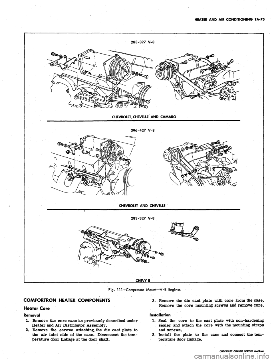
Fig.
Ill—Compressor Mount—V-8 Engines
COMFORTRON HEATER COMPONENTS
Heater Core
Removal
1.
Remove the core case as previously described under
Heater and Air Distributor Assembly.
2.
Remove the screws attaching the die cast plate to
the air inlet side of the case. Disconnect the tem-
perature door linkage at the door shaft.
3.
Remove the die cast plate with core from the case.
Remove the core mounting screws and remove core.
Installation
1.
Seal the core to the cast plate with non-hardening
sealer and attach the core with the mounting straps
and screws.
2.
Install the plate to the case and connect the tem-
perature door linkage.
CHEVROLET CHASSIS SERVICE MANUAL