engine CHEVROLET CAMARO 1967 1.G Chassis Owner's Manual
[x] Cancel search | Manufacturer: CHEVROLET, Model Year: 1967, Model line: CAMARO, Model: CHEVROLET CAMARO 1967 1.GPages: 659, PDF Size: 114.24 MB
Page 42 of 659
HEATER AND AIR CONDITIONING 1A-19
Transducer
The transducer will produce a vacuum output that is
completely adjustable by varying the input voltage which
is provided by the amplifier. An increase in the applied
voltage results in a reduced vacuum output.
Power Servo
The power servo receives a vacuum signal from the
transducer, and it is capable of assuming any position
that is called for by the sensors, amplifier, and trans-
ducer. The power servo performs the following functions:
1.
Positions the temperature mix door via the tern-
perature door link. The position of this door~"de-
termihes the portions of hot and cold air being
blended and discharged into the car.
2.
Operates the power servo vacuum valve which de-
termines the air flow paths for heating and air
conditioning.
3.
Contains a printed circuit board which controls the
blower speed. The power servo position determines
the blower speed, but the control lever switch can
override the blower program depending upon the
customer's preference.
4.
Contains the "Hi" blower delay thermistor and the
"master delay thermistor".
Outside Air Diaphragm
When there is no vacuum applied to the hose, the out-
side air door is closed under spring tension. With the
door closed, air is taken from the inside of the auto-
mobile and re-circulated. Applying vacuum to the dia-
phragm opens the door for outside air.
Mode Door Diaphragm
Located behind the duct work, the mode door diaphragm
directs the air flow out either the air conditioning outlets,
the heater floor outlet, or both the heater and air con-
ditioning outlets. This is a push-pull type diaphragm
actuated by vacuum through two hoses and controlled by
the power servo vacuum switch.
Defroster Door
The defroster door is in the defog position until vacuum
is applied to the actuator to obtain either full heat or full
de-ice position.
High Blower Delay Thermistor
The high blower delay thermistor is located on the
power servo housing under the power servo vacuum valve
and printed circuit board assemblies. The function of the
thermistor is to operate the blower at a reduced speed
when the control is in the HI FRONT position until the
residual cold air is discharged from the duct work. This
function occurs when the blower first comes "on" in cold
weather.
Vacuum Tank
During heavy acceleration, the vacuum supply from
the carburetor drops. The vacuum tank, using a^ check
valve, stores vacuum so that under these conditions
vacuum will be available for the Comfortron.
Thermal Vacuum Valve (Hot Water Vacuum Switch)
When engine coolant temperature reaches 75°F, the
valve opens and supplies vacuum to the outside air door
if the system is calling for outside air.
Master Delay Thermister
This thermistor delays the initial operation of the
blower when the system is in the heat mode. In cold
weather this allows outside ram air to flow through the
system thereby purging the cold air in the ducts gradually
until the coolant reaches about 105°F. Then, the termis-
tor passes enough current to energize the master delay
relay which powers the blower at about nine volts.
Vacuum Relay Valve
This relay valve will shut off transducer vacuum to the
power servo whenever the vacuum from the engine intake
manifold falls below the vacuum in the power servo
supply line (engine stopped or operating at low manifold
vacuum). This causes the power servo to be held in
position when the vacuum supply falls too low to maintain
servo control.
Vacuum Bleeder
A vacuum bleeder insures that the outside air door will
close (diaphragm will bleed down) after the system has
been shut down. This prevents outside air from entering
when starting the system on a cold day before the engine
coolant temperature reaches 75°F.
Sun—Ambient Sensor
The sun-ambient sensor measures the temperature of
the air entering the air intake grille in front of the wind-
shield. The sensor is exposed to sun light so that it can
lower the in-car temperature slightly when the sun
is shining.
Ambient Switch
The ambient switch operates the air conditioning com-
pressor clutch. When the outside temperature is above
40° F. the switch will be closed and the compressor will
be running. This switch is included as| part of the sun-
ambient sensor assembly, but operates independently.
Resistor Assembly
The blower resistors are located in the evaporator
housing. The printed circuit board switch in the power
servo determines which of the resistors is being used,
and as in conventional systems, the resistors control the
blower speed.
System Operation
When starting the Comfortron System in cold weather,
the following sequence of events occurs:
1.
Initially the system is inoperative. In LO FRONT
position the master delay thermistor is warming
(self-heating because current is flowing through it)
CHEVROLET CHASSIS SERVICE MANUAL
Page 43 of 659
HEATER AND AIR CONDITIONING 1A-20
and its resistance is decreasing. In the HI FRONT
position, two thermistors (the master delay and high
blower delay thermistors) are warming. The air
door is in recirculation position until the engine
coolant reaches 75 degrees.
2.
The coolant reaches then 75 degrees and the thermal
vacuum valve opens applying vacuum to the air door
to admit outside air (unless the temperature dial is
set for cooling). Ram air will flow through the sys-
tem when the car is moving.
3.
Next, the master delay thermistor attains the tem-
perature at which it will pass sufficient current to
close the circuit through the master delay relay.
The relay circuit powers the blower motor at 9 volts.
4.
If the control is in the HI FRONT position, the high
blower delay thermistor will close the circuit
through the high blower relay which supplies full
available voltage to the blower motor. This function
occurs after the master delay thermistor has taken
effect because the high blower delay thermistor
uses the master delay type thermistor with a 10 ohm
1/4 watt resistor connected in
.
series. The nigh
blower delay thermistor must then warm to a higher
temperature than the master delay thermistor before
its resistance (plus that of the 10 ohm resistor)
drops enough to actuate the high blower relay.
5. If the controls are set for DE ICE, full outside air
and full voltage to the blower motor are effective
immediately regardless of temperatures or elapsed
times o
In accomplishing automatic control, the system follows
three steps to transform an electronic signal into me-
chanical energy through which the control is achieved.
Electronic Circuit
Two temperature sensors (Thermistors), and the duct
potentiometer connected in series, are located so as to
sense the temperature of the outside air, inside air and
system output air. The resistance of each sensor will
vary according to its temperature. The control head
temperature dial varies in resistance as it is adjusted by
the operator to suit his comfort requirements. The
resistance of the temperature dial control is applied
directly to the amplifier and is not in series with the
sensors and duct potentiometer. Thus temperature dif-
ferences in the sensor string plus the requirements fed
into the system by the operator cause changes in total
circuit resistance which allow a varying voltage flow
through the circuit.
Changing the Electronic Signal to Electrical Voltage
This minute voltage flow from the sensor string -
temperature dial circuit - is fed into the amplifier where
it is transformed into a usable amplifier output voltage,
the strength of which is determined by the strength of the
original amplifier input signal. This voltage is then
supplied to the transducer.
Changing the Electrical Voltage to a Vacuum Signal
Amplifier output voltage, varying according to tem-
perature requirements, is converted by the Transducer
into a modulator transducer output vacuum. This modu-
lated vacuum is applied to the Power Servo.
Changing the Vacuum Signal to Mechanical Energy
The Power Servo, controlled by the modulated Trans-
ducer output vacuum, operates the vacuum electrical and
mechanical components of the system as required to
provide automatic control of system operation.
Other major system components are mounted con-
ventionally in the engine compartment. Underhood com-
ponents and system airflow remain much the same as in
the Four-Season system except for the addition of the
automatic control provisions. The system operates on
100%
outside air, a mixture of outside and inside air, or
100%
recirculated air depending on the demands of the
system. The diaphragm operated .air selector door will
modulate outside air to the system during maximum air
conditioning requirements when the control unit is in
"Hi Front" position. Control of the blower is also com-
pletely automatic and dependent upon system demands.
Controls
The Comfortron controls the Chevrolet air conditioner
and heater in such a precise manner that the automobile
temperature remains relatively constant under all driving
conditions. By adjusting the thumb wheel on the Control
Head to any temperature desired between 65° and 85° F.
(See Figure 27) the automatic system will adjust the in-
car temperature even though the outside weather condi-
tions may vary considerably. The system will provide
maximum capacity for heating or cooling until the in-car
temperature reaches the pre-set Control Head Tempera-
ture. Where cooling is required, the system will start
immediately upon being turned "ON". During marginal
ambient temperatures the system will not always start
at the highest blower speeds of the control setting.
Therefore, occasionally the system can't be heard
starting*
Five over-riding functions are available so that special
conditions can be handled. Each Control Head function
will be discussed in detail below:
"Off" Position
In the "Off" position, the blower is turned off and the
outside air door is closed. No outside air should enter
the automobile.
"Lo Front" Position
The blower has five low to moderate speeds; Hi, M3,
M2,
M1 and Lo. The blower voltage will shift as directed
by the automatic controls. The "Lo Front" position
provides a quieter mode of automatic operation due to
reduction of blower noise.
"Hi Front" Position
The "Hi Front" position provides five high blower
speeds as called for by the automatic controls: The use
of the "Hi" blower speed results in a rapid cool down in
hot weather and rapid heating during cold weather. As
the in-car temperature approaches the temperature set-
ting on the Comfortron Control Head, the blower speed
will change, provided mild outside temperatures are
experienced. During very hot or cold weather, the blower
will reduce its speed only to the point where it is still
capable of maintaining the correct inrcar temperature.
"Rear" Position
The "Rear" position provides five high blower speeds.
The automatic controls select these speeds and blend the
discharge air to the proper temperature. By the use of
high blower speeds, increased airflow is obtained for
better rear seat passenger comfort.
CHEVROLET CHASSIS SERVICE MANUAL
Page 44 of 659
HEATER AND AIR CONDITIONING 1A-21
"De-Fog"
Position
In the event that the front windshield should require
removal of a fogging condition, the owner at his option
may direct air to the windshield. The "De-Fog" position
directs part of the air to the windshield while retaining a
certain amount through the floor outlets. The temper-
ature of the air remains the same as it was prior to the
control being placed in the "De-Fog" position. Five
blower speeds are available. The temperature of the air
and the blower speed are selected by the automatic
controls and are dependent upon the in-car temperature.
"De-Ice" Position
The "De-Ice" position provides full heat with "Hi"
blower directing the entire airflow to the windshield to
melt ice. The automatic controls are completely defeated
and as a result, full heat with "Hi" blower are the only
conditions that can be received. The system will turn on
immediately in this position even though the engine
coolant might be cold.
General Information
Three start up conditions can be achieved with
Comfortron.
Weather
Cold
Method of Starting System
System starts as soon as engine coolant is
hot.
Hot System starts immediately when AC is
required.
Any System starts immediately in "De-Ice"
position.
UNIVERSAL SYSTEM
A self-contained unit, the dealer installed Universal
System operates on recirculated air only and entirely
independent of the vehicle heater. Recirculated inside air
is drawn into the unit, passed through the evaporator core
and into the car through the adjustable outlets in the
evaporator case. The entire unit mounts compactly
beneath the dash. Temperature control is by means of a
thermostatic switch.
The compressor used with the Universal System is
identical to that used for the Four-Season system except
for displacement. Underhood components are similar in
placement to the Four-Season system.
Controls
Universal system controls are the AIR knob controlling
the three speed blower motor switch and the TEMP knob
which controls the setting of the thermostatic switchi
Switch adjustment is covered elsewhere in this section.
When operating this system the Heater must be fully off.
CHEVY II ALL-WEATHER SYSTEM
The Chevy n All-Weather Air Conditioning System,
Figure 33, operates in conjunction with the heater to
provide a complete air conditioning system operating on
either outside air, recirculated air or a combination of
both. The cooling unit attaches to the heater distributor
and utilizes the heater blower. Several controls allow
full use of either the heating or cooling features of the
system. During marginal weather, it is possible to pro-
vide heated air at floor level and cooled air at breath
level.
A schematic view of the air conditioning underdash
components is provided in Figure 34 to aid in under-
standing airflow and control operation.
The evaporator assembly, located in the passenger
compartment attached directly to the heater distributor,
contains the evaporator core, expansion valve, thermo-
static switch and the air conditioning "ON" knob. The
thermostatic switch, utilized as the cooling control, feels
the temperature of the cooled air leaving the evaporator
core and turns the compressor on and off in accordance
with cooling needs. Refrigerant lines connect the evap-
orator assembly to the other system components located
in the engine compartment.
The six cylinder air conditioning compressor, com-
pletely field serviceable, is bracket-mounted to the
engine and is belt driven from the crankshaft pulley. A
muffler assembly, designed to eliminate compressor
pulsations is an integral part of the compressor con-
nector block. The condenser is mounted on the radiator
support just ahead of the engine radiator. The receiver-
dehydrator, with its sight glass, is located on the right
fender skirt.
Controls
Control of the air conditioning system is achieved
through the use of the heater control on the instrument
panel as well as the two knobs located on the air condi-
tioning unit itself (fig. 35).
Air Conditioning "ON" Knob
Labeled "Pull for Air Cond.", this knob diverts air-
flow from the floor distributor and through the air condi-
tioning unit. Initial movement of this knob also actuates a
switch, located at the damper door, which energizes the
compressor clutch thus putting the system into operation
and under the control of the thermostatic switch.
Temp-Cool Knob
This knob controls the thermostatic switch. Turn the
knob clockwise for more cooling, counter-clockwise for
less cooling.
Air Lever
This lever actuates the damper within the assembly
which chooses between recirculated air or outside air.
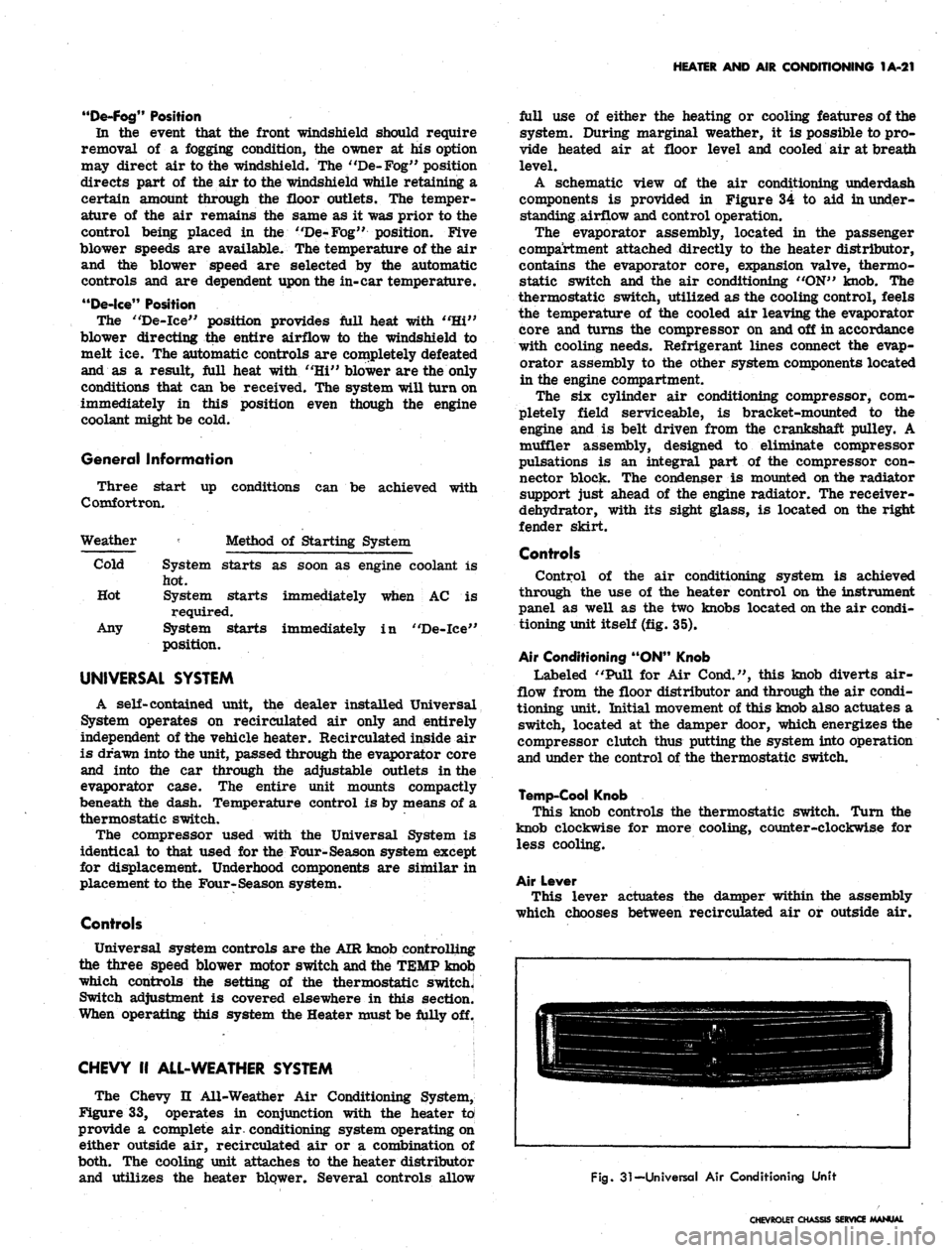
Fig.
31-Universal Air Conditioning Unit
CHEVROLET CHASSIS SERVICE MANUAL
Page 47 of 659
HEATER AND AIR. CONDITIONING 1A-24
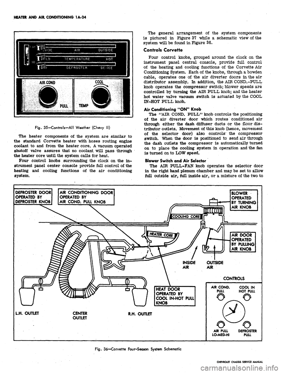
Fig. 35-Controls-AII Weather (Chevy II)
The heater components of the system are similar to
the standard Corvette heater with hoses routing engine
coolant to and from the heater core. A vacuum operated
shutoff valve assures that no coolant will pass through
the heater core until the system calls for heat.
Four control knobs surrounding the clock on the in-
strument panel center console provide full control of the
heating and cooling functions of the air conditioning
system.
The general arrangement of the system components
is pictured in Figure 37 while a schematic view of the
system will be found in Figure 36.
Controls Corvette
Four control knobs, grouped around the clock on the
instrument panel central console, provide full control
of the heating and cooling functions of the Corvette Air
Conditioning System. Each of the knobs, through a bowden
cable, operates one of the air diverter doors in the air
distributor assembly. In addition, the AIR COND.-PULL
knob operates the compressor switch; blower speeds are
controlled by turning the AIR PULL knob; and the heater
hot water valve vacuum switch is actuated by the COOL
IN-HQT PULL knob.
Air Conditioning "ON" Knob
The "AIR COND. PULL" knob controls the positioning
of the air diverter door which routes conditioned air
through either the dash diffuser ducts or the floor dis-
tributor outlets. Movement of this knob (hence, movement
of the selector door) also controls' the compressor
switch. When the door is positioned to send air through
the dash outlets the compressor is automatically turned
on to place the cooling system in operation and the fan
is turned on to LOW speed.
Blower Switch and Air Selector
The AIR PULL-FAN knob operates the selector door
in the right hand plenum chamber and may be set to allow
full outside air, full inside air, or a mixture of the two to
DEFROSTER DOOR
OPERATED BY
DEFROSTER KNOB
AIR CONDITIONING DOOR
OPERATED BY
AIR COND. PULL KNOB
BLOWER
OPERATED
BY TURNING
AIR KNOB
AIR DOOR
OPERATED
BY PULLING
AIR KNOB
OUTSIDE
AIR
CONTROLS
HEAT DOOR
OPERATED BY
COOL IN-HOT PULL
KNOB
L.H. OUTLET
CENTER
OUTLET
R.H. OUTLET
AIR COND.
PULL
COOL IN
HOT PULL
AIR PULL
LO-MED-HI
DEFROSTER
PULL
Fig.
36—Corvette Four-Season System Schematic
CHEVROLET CHASSIS SERVICE MANUAL
Page 48 of 659
HEATER AND AIR CONDITIONING 1A-25
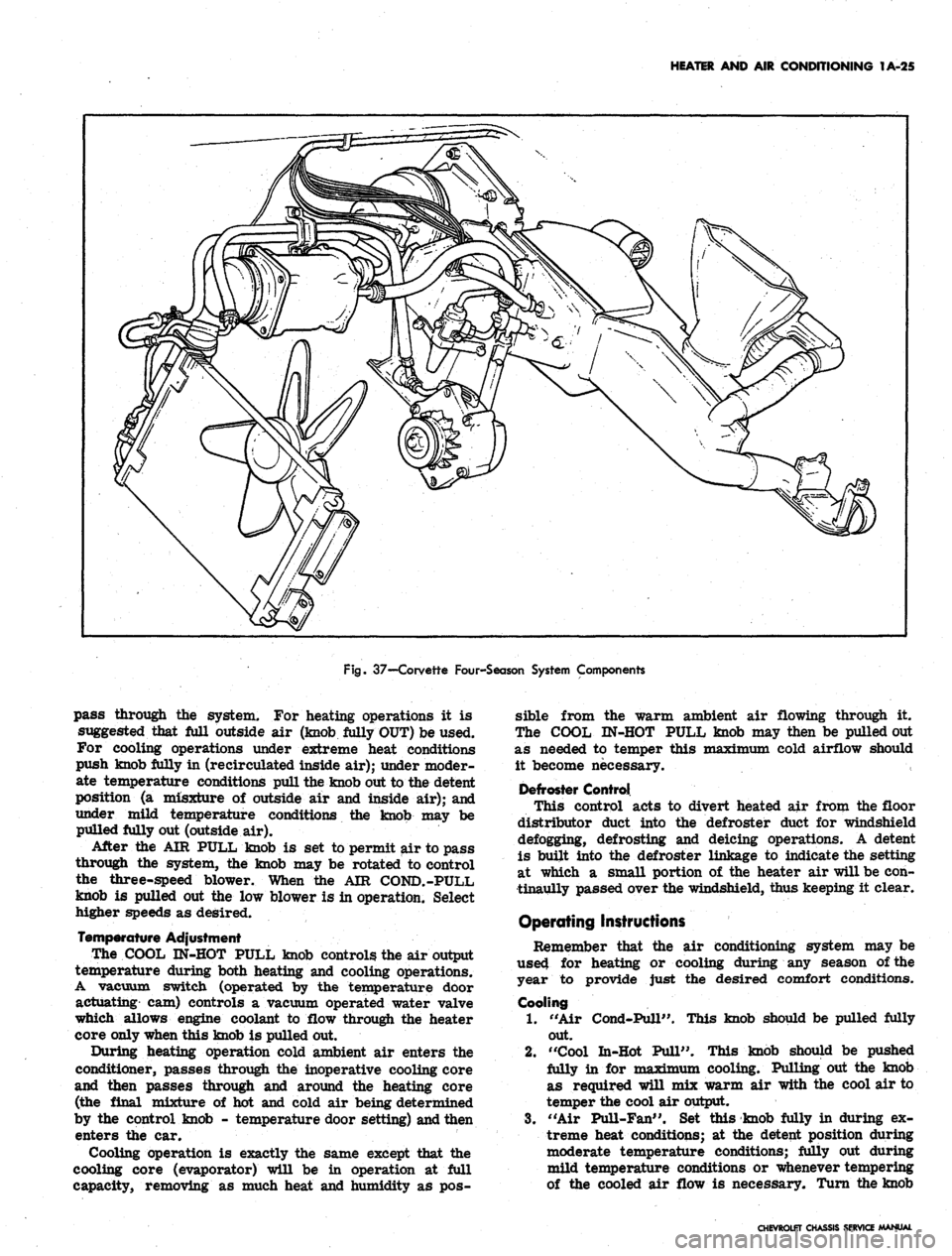
Fig.
37—-Corvette Four-Season System Components
pass through the system. For heating operations it is
suggested that Ml outside air (knob Mly OUT) be used.
For cooling operations under extreme heat conditions
push knob fully in (recirculated inside air); under moder-
ate temperature conditions pull the knob out to the detent
position (a misxture of outside air and inside air); and
under mild temperature conditions the knob may be
pulled fully out (outside air).
After the AIR PULL knob is set to permit air to pass
through the system, the knob may be rotated to control
the three-speed blower. When the AIR COND.-PULL
knob is pulled out the low blower is in operation. Select
higher speeds as desired.
Temperature Adjustment
The COOL IN-HOT PULL knob controls the air output
temperature during both heating and cooling operations.
A vacuum switch (operated by the temperature door
actuating cam) controls a vacuum operated water valve
which allows engine coolant to flow through the heater
core only when this knob is pulled out.
During heating operation cold ambient air enters the
conditioner, passes through the inoperative cooling core
and then passes through and around the heating core
(the final mixture of hot and cold air being determined
by the control knob - temperature door setting) and then
enters the car.
Cooling operation is exactly the same except that the
cooling core (evaporator) will be in operation at Ml
capacity, removing as much heat and humidity as pos-
sible from the warm ambient air flowing through it.
The COOL IN-HOT PULL knob may then be pulled out
as needed to temper this maximum cold airflow should
it become necessary.
Defroster Control
This control acts to divert heated air from the floor
distributor duct into the defroster duct for windshield
defogging, defrosting and deicing operations. A detent
is built into the defroster linkage to indicate the setting
at which a small portion of the heater air will be con-
tinaully passed over the windshield, thus keeping it clear.
Operating Instructions
Remember that the air conditioning system may be
used for heating or cooling during any season of the
year to provide just the desired comfort conditions.
Cooling
1.
"Air Cond-Pull". This knob should be pulled fully
out.
2.
"Cool In-Hot Pull". This knob should be pushed
fully in for maTriTr»"Tn cooling. Pulling out the knob
as required will mix warm air with the cool air to
temper the cool air output.
3.
"Air Pull-Fan". Set this knob fully in during ex-
treme heat conditions; at the detent position during
moderate temperature conditions; fully out during
mild temperature conditions or whenever tempering
of the cooled air flow is necessary. Turn the knob
CHEVROLET CHASSIS SERVICE MANUAL
Page 53 of 659
HEATER AND AIR CONDITIONING 1A-30
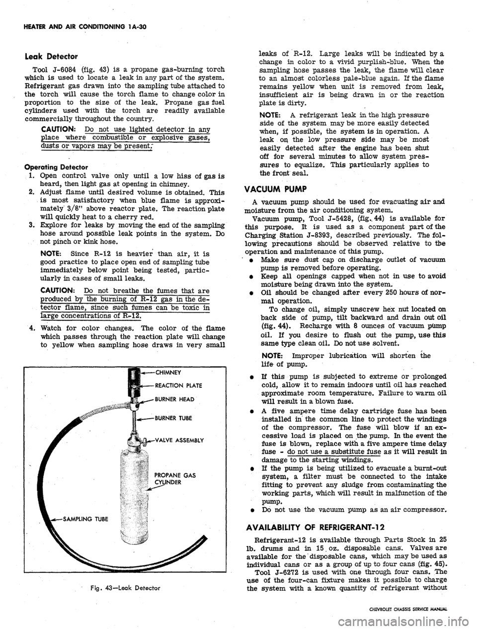
Leak Detector
Tool J-6084 (fig. 43) is a propane gas-burning torch
which is used to locate a leak in any part of the system.
Refrigerant gas drawn into the sampling tube attached to
the torch will cause the torch flame to change color in
proportion to the size of the leak. Propane gas fuel
cylinders used with the torch are readily available
commercially throughout the country.
CAUTION: Do not use lighted detector in any
place where combustible or explosive gases,
dusts or vapors may be present;
Operating Detector
1.
Open control valve only until a low hiss of gas is
heard, then light gas at opening in chimney.
2.
Adjust flame until desired volume is obtained. This
is most satisfactory when blue flame is approxi-
mately 3/8" above reactor plate. The reaction plate
will quickly heat to a cherry red.
3.
Explore for leaks by moving the end of the sampling
hose around possible leak points in the system. Do
not pinch or kink hose.
NOTE: Since R-12 is heavier than air, it is
good practice to place open end of sampling tube
immediately below point being tested, partic-
ularly in cases of small leaks.
CAUTION: Do not breathe the fumes that are
produced by the burning of R-12 gas in the de-
tector flame, since such fumes can be toxic in
large concentrations of R?»12.
4.
Watch for color changes. The color of the flame
which passes through the reaction plate will change
to yellow when sampling hose draws in very small
CHIMNEY
REACTION PLATE
BURNER HEAD
Fig.
43—Leak Detector
leaks of R-12. Large leaks will be indicated by a
change in color to a vivid purplish-blue. When the
sampling hose passes the leak, the flame will clear
to an almost colorless pale-blue again. If the flame
remains yellow when unit is removed from leak,
insufficient air is being drawn in or the reaction
plate is dirty.
NOTE: A refrigerant leak in the high pressure
side of the system may be more easily detected
when, if possible, the system is in operation. A
leak on the low pressure side may be most
easily detected after the engine has been shut
off for several minutes to allow system pres-
sures to equalize. This particularly applies to
the front seal.
VACUUM PUMP
A vacuum pump should be used for evacuating air and
moisture from the air conditioning system.
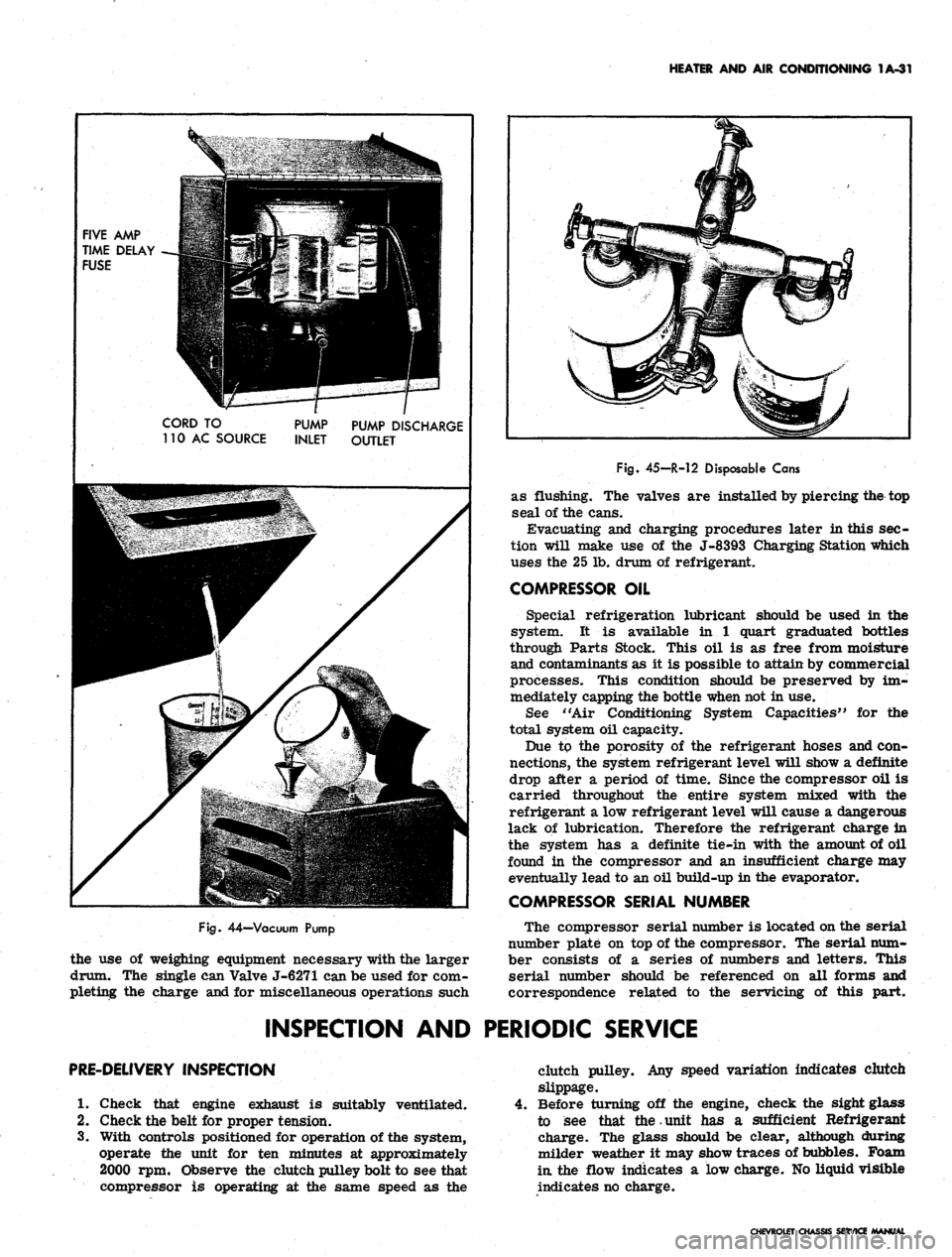
Vacuum pump, Tool J-5428, (fig.. 44) is available for
this purpose. It is used as a component part of the
Charging Station J-8393, described previously. The fol-
lowing precautions should be observed relative to tbe
operation and maintenance of this pump.
' • Make sure dust cap on discharge outlet of vacuum
pump is removed before operating.
• Keep all openings capped when not in use to avoid
moisture being drawn into the system.
• Oil should be changed after every 250 hours of nor-
mal operation.
To change oil, simply unscrew hex nut located on
back side of pump, tilt backward and drain out oil
(fig. 44). Recharge with 8 ounces of vacuum pump
oil.
If you desire to flush out the pump, use this
same type clean oil. Do not use solvent.
NOTE: Improper lubrication will shorten the
life of pump.
• If this pump is subjected to extreme or prolonged
cold, allow it to remain indoors until oil has reached
approximate room temperature. Failure to warm oil
will result in a blown fuse.
• A five ampere time delay cartridge fuse has been
installed in the common line to protect the windings
of the compressor. The fuse will blow if an ex-
cessive load is placed on the pump. In the event the
fuse is blown, replace with a five ampere time delay
fuse - do not use a substitute fuse as it will result in
damage to the starting windings.
• If the pump is being utilized to evacuate a burnt-out
system, a filter must be connected to the intake
fitting to prevent any sludge from contaminating the
working parts, which will result in malfunction of the
pump.
• Do not use the vacuum pump as an air compressor.
AVAILABILITY OF REFRIGERANT-12
Refrigerant-12 is available through Parts Stock in 25
lb.
drums and in 15 oz. disposable cans. Valves are
available for
the"
disposable cans, which may be used as
individual cans or as a group of up to four cans (fig. 45).
Tool J-6272 is used with one through four cans. The
use of the four-can fixture makes it possible to charge
the system with a known quantity of refrigerant without
CHEVROLET CHASSIS SERVICE MANUAL
Page 54 of 659
HEATER
AND AIR
CONDITIONING
1A-31
FIVE
AMP
TIME DELAY
FUSE
CORD
TO
110
AC
SOURCE
PUMP
INLET
PUMP DISCHARGE
OUTLET
Fig.
44—Vacuum Pump
the use of weighing equipment necessary with the larger
drum. The single can Valve J-6271 can be used for com-
pleting the charge and for miscellaneous operations such
Fig.
45-R-12 Disposable Cans
as flushing. The valves are installed by piercing the top
seal of the cans.
Evacuating and charging procedures later in this sec-
tion will make use of the J-8393 Charging Station which
uses the 25 lb. drum of refrigerant.
COMPRESSOR OIL
Special refrigeration lubricant should be used in the
system. It is available in 1 quart graduated bottles
through Parts Stock. This oil is as free from moisture
and contaminants as it is possible to attain by commercial
processes. This condition should be preserved by im-
mediately capping the bottle when not in use.
See "Air Conditioning System Capacities" for the
total system oil capacity.
Due to the porosity of the refrigerant hoses and con-
nections, the system refrigerant level will show a definite
drop after a period of time. Since the compressor oil is
carried throughout the entire system mixed with the
refrigerant a low refrigerant level will cause a dangerous
lack of lubrication. Therefore the refrigerant charge in
the system has a definite tie-in with the amount of oil
found in the compressor and an insufficient charge may
eventually lead to an oil build-up in the evaporator.
COMPRESSOR SERIAL NUMBER
The compressor serial number is located on the serial
number plate on top of the compressor. The serial num-
ber consists of a series of numbers and letters. This
serial number should be referenced on all forms and
correspondence related to the servicing of this part.
INSPECTION AND PERIODIC SERVICE
PRE-DELIVERY INSPECTION
1.
Check that engine exhaust is suitably ventilated.
2.
Check the belt for proper tension.
3.
With controls positioned for operation of the system,
operate the unit for ten minutes at approximately
2000 rpm. Observe the clutch pulley bolt to see that
compressor is operating at the same speed as the
clutch pulley. Any speed variation indicates clutch
slippage.
Before turning off the engine, check the sight glass
to see that the.unit has a sufficient Refrigerant
charge. The glass should be clear, although during
milder weather it may show traces of bubbles. Foam
in.
the flow indicates a low charge. No liquid visible
indicates no charge.
CHEVROLET CHASSIS SERVICE MANUAL
Page 55 of 659
HEATER AND AIR CONDITIONING 1A-32
5.
Check hose clamp connections. If clamp screw torque
is less than 10 lb. in., retighten to 20-25 lb. in. Do
not tighten to new hose specifications or hose leak-
age may occur.
6. If there is evidence of an oil leak, check the com-
pressor to see that the oil charge is satisfactory.
7.
Check the system controls for proper operation.
6000 MILE INSPECTION
1.
Check unit for any indication of a refrigerant leak.
2.
If there is an indication of an oil leak, check the
compressor proper oil charge.
3.
Check sight glass for proper charge of Refrigerant-
12.
4.
Tighten the compressor brace and support bolts and
check the belt tension.
5.
Check hose clamp connections as in step 5 above.
6. Check thermostatic switch setting (Universal and
All-Weather Systems.)
PERIODIC SERVICE
• Inspect condenser regularly to be sure that it is not
plugged with leaves or other foreign material.
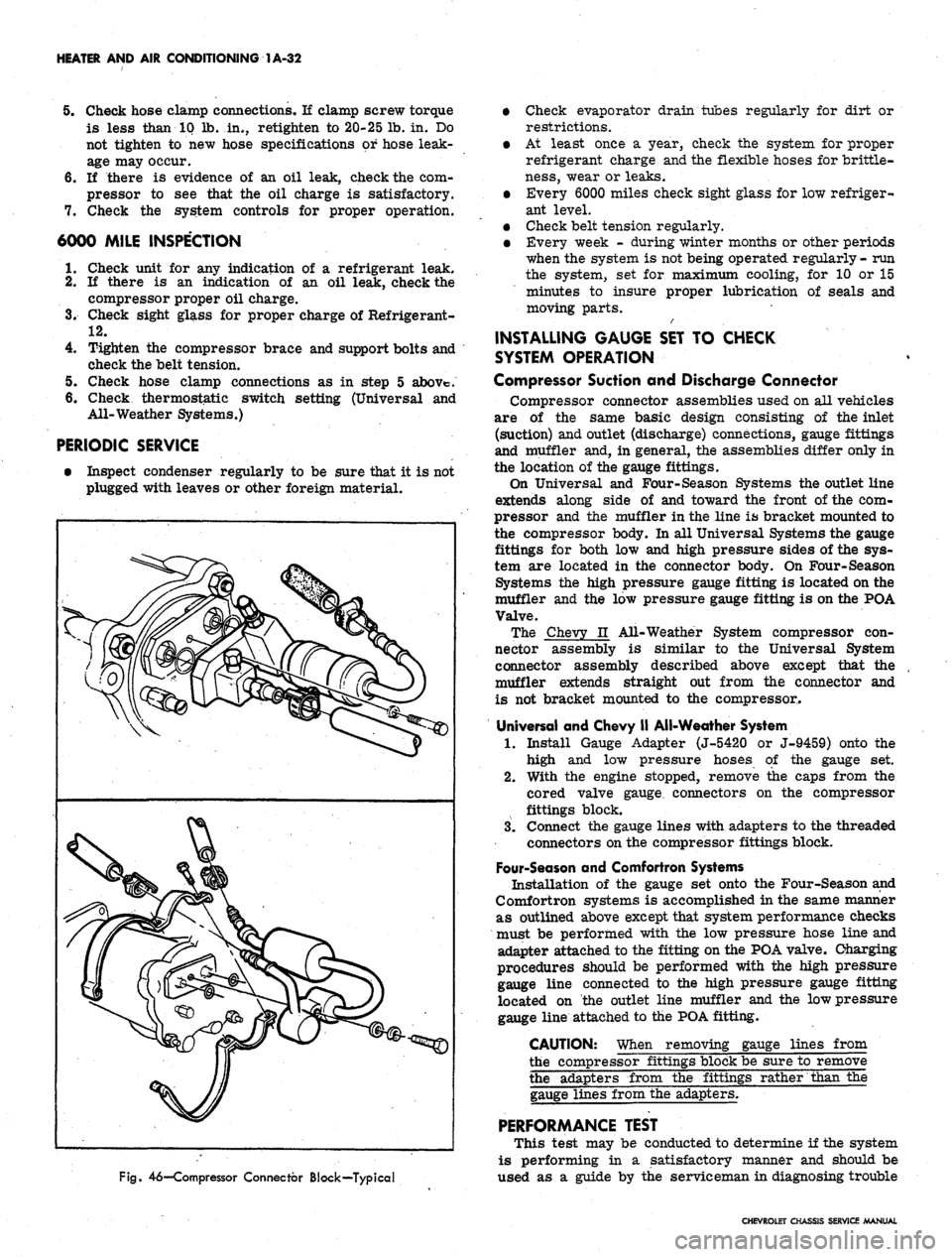
Fig.
46—Compressor Connector Block—Typical
• Check evaporator drain tubes regularly for dirt or
restrictions.
• At least once a year, check the system for proper
refrigerant charge and the flexible hoses for brittle-
ness,
wear or leaks.
• Every 6000 miles check sight glass for low refriger-
ant level.
• Check belt tension regularly.
• Every week - during winter months or other periods
when the system is not being operated regularly- run
the system, set for maximum cooling, for 10 or 15
minutes to insure proper lubrication of seals and
moving parts.
INSTALLING GAUGE SET TO CHECK
SYSTEM OPERATION
Compressor Suction and Discharge Connector
Compressor connector assemblies used on all vehicles
are of the same basic design consisting of the inlet
(suction) and outlet (discharge) connections, gauge fittings
and muffler and, in general, the assemblies differ only in
the location of the gauge fittings.
On Universal and Four-Season Systems the outlet line
extends along side of and toward the front of the com-
pressor and the muffler in the line is bracket mounted to
the compressor body. In all Universal Systems the gauge
fittings for both low and high pressure sides of the sys-
tem are located in the connector body. On Four-Season
Systems the high pressure gauge fitting is located on the
muffler and the low pressure gauge fitting is on the POA
Valve.
The Chevy n All-Weather System compressor con-
nector assembly is similar to the Universal System
connector assembly described above except that the
muffler extends straight out from the connector and
is not bracket mounted to the compressor.
Universal and Chevy II All-Weather System
1.
Install Gauge Adapter (J-5420 or J-9459) onto the
high and low pressure hoses of the gauge set.
2.
With the engine stopped, remove the caps from the
cored valve gauge, connectors on the compressor
fittings block.
3.
Connect the gauge lines with adapters to the threaded
connectors on the compressor fittings block.
Four-Season and Comfortron Systems
Installation of the gauge set onto the Four-Season and
Comfortron systems is accomplished in the same manner
as outlined above except that system performance checks
must be performed with the low pressure hose line and
adapter attached to the fitting on the POA valve. Charging
procedures should be performed with the high pressure
gauge line connected to the high pressure gauge fitting
located on the outlet line muffler and the low pressure
gauge line attached to the POA fitting.
CAUTION: When removing gauge lines from
the compressor fittings block be sure to remove
the adapters from the fittings rather than the
gauge lines from the adapters.
PERFORMANCE TEST
This test may be conducted to determine if the system
is performing in a satisfactory manner and should be
used as a guide by the serviceman in diagnosing trouble
CHEVROLET CHASSIS SERVICE MANUAL
Page 56 of 659
HEATER AND AIR CONDITIONING 1A-33
within the system. The following fixed conditions must be
adhered to in order to make it possible to compare the
performance of the system being tested with the stan-
dards below:
1.
Doors and windows closed. (Car inside or in shade.)
2.
Hood up and engine exhaust suitably ventilated.
3.
Vehicle in NEUTRAL with engine running at 2000
rpm.
4.
Air Conditioning controls set for -
• Maximum cooling.
• High blower speed.
5.
TEMP knob and AIR knob set for full recirculating
air. On Comfortron systems* move the control lever
to REAR and pull the white vacuum hose from the
transducer. Plug the hose. An alternate method is to
install the J-22368 Tester (described later in this
section) and operate it on MANUAL control to main-
tain maximum cooling and blower speed.
6. Gauge set installed.
7.
System settled out (run-in approximately
10
minutes).
8. A thermometer placed in front of vehicle grille and
another in the right hand diffuser outlet.
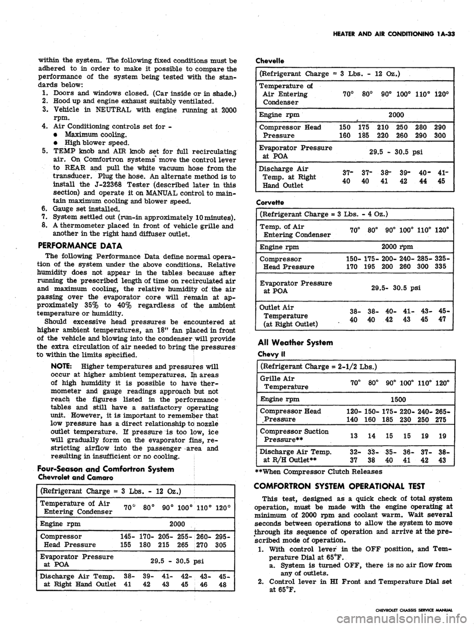
PERFORMANCE DATA
The following Performance Data define normal opera-
tion of the system under the above conditions. Relative
humidity does not appear in the tables because after
running the prescribed length of time on recirculated air
and maximum cooling, the relative humidity of the air
passing over the evaporator core will remain at ap-
proximately 35% to 40% regardless of the ambient
temperature or humidity.
Should excessive head pressures be encountered at
higher ambient temperatures, an 18" fan placed in front
of the vehicle and blowing into the condenser will provide
the extra circulation of air needed to bring the pressures
to within the limits specified.
NOTE: Higher temperatures and pressures will
occur at higher ambient temperatures, fti areas
of high humidity it is possible to have ther-
mometer and gauge readings approach but not
reach the figures listed in the performance
tables and still have a satisfactory operating
unit. However, it is important to remember that
low pressure has a direct relationship to nozzle
outlet temperature. If pressure is too low, ice
will gradually form on the evaporator fins, re-
stricting airflow into the passenger area and
resulting in insufficient or no cooling.
Four-Season and Comfortron System
Chevrolet and Camaro
Chevelle
(Refrigerant
Charge
=
Temperature
of Air
Entering Condenser
Engine rpm
Compressor
Head Pressure
Evaporator Pressure
at POA
Discharge Air Temp,
at Right Hand Outlet
3
Lbs. -
70°
145-
155
38-
41
80°
170-
180
12 02
90°
.)
100°
2000
205-
215
29.5 -
39-
42
41-
43
255-
265
30.5
42-
45
110°
260-
270
psi
43-
46
120°
295-
305
45-
48
(Refrigerant Charge =
Temperature of
Air Entering
Condenser
Engine rpm
Compressor Head
Pressure
Evaporator
Pressure
at
POA
Discharge Air
Temp, at Right
Hand Outlet
3 Lbs. -
70°
150
160
37-
40
80°
175
185
12 Oz.)
90° 100°
2000
210 250
220 260
29.5 - 30.5
37-
40
38-
39-
41 42
110°
280
290
psi
40-
44
120°
290
300
41-
45
Corvette
(Refrigerant Charge =
Temp, of Air
Entering Condenser
Engine rpm
Compressor
Head Pressure
Evaporator
Pressure
at
POA
Outlet
Air
Temperature
(at Right
Outlet)
3
Lbs.
70°
150-
170
38-
40
- 4 Oz.)
80°
175-
195
29
38-
40
90°
2000
200-
200
100°
i*pm
240-
260
110°
285-
300
5-
30.5 psi
40-
42
41-
43
43-
45
120°
325-
335
45-
47
Alt Weather System
Chevy II
(Refrigerant
Charge
=
Grille Air
Temperature
Engine rpm
Compressor Head
Pressure
Compressor Suction
Pressure**
Discharge Air Temp,
at R/H Outlet**
2-1/2 Lbs.)
70°
120-
140
13
32-
37
80°
150-
160
14
CO
OO
CO
CO
90°
100°
1500
175-
185
15
35-
40
220-
230
15
36-
41
110°
240-
250
19
37-
42
120°
265-
275
19
38-
43
**When Compressor Clutch Releases
COMFORTRON SYSTEM OPERATIONAL TEST
This test, designed as a quick check of total system
operation, must be made with the engine operating at
minimum of 2000 rpm and coolant warm. Wait several
seconds between operations to allow the system to move
through its sequence of operation and arrive at the pre-
scribed mode of operation.
1.
With control lever in the OFF position, and Tem-
perature Dial at 65°F.
a. System is turned OFF, there is no air flow from
any of outlets.
2.
Control lever in HI Front and Temperature Dial set
at65°F.
CHEVROLET CHASSIS SERVICE MANUAL
Page 57 of 659
HEATER AND AIR CONDITIONING 1A-34
a. Blower comes on High speed.
b.
Cold air comes from A/C outlets.
3.
Rotate Temperature Dial to 85°F.
a. Blower speed will decrease to Low speed then
increase to Medium or High.
b.
Air temperature changes from Cold to Hot and
comes out heater outlet.
4.
Move control lever to LOW Front, with Temperature
Dial at 85°F. Blower operates at Low and Medium
speeds.
5.
Move control lever to Rear, set Temperature Dial
at 65°F.
a. Blower goes to High speed and maintains high
air flow.
b.
All air comes from A/C outlets.
6. Move control lever to DE-FOG.
a. Blower is on Medium or High Speeds.
b.
Air comes from Defroster and Heater Outlets.
7.
Move control lever to DE-ICE.
a. Blower is on High Speed.
b.
Air temperature goes to warm and most of air
comes from defroster nozzle, with small amount
of air coming from heater outlet.
c. Outside air door is open - (door valve is closed
to car body).
8. Move control lever to REAR (dial at 65°). Outside
air door moves outboard. (Door valve is open to
car body).
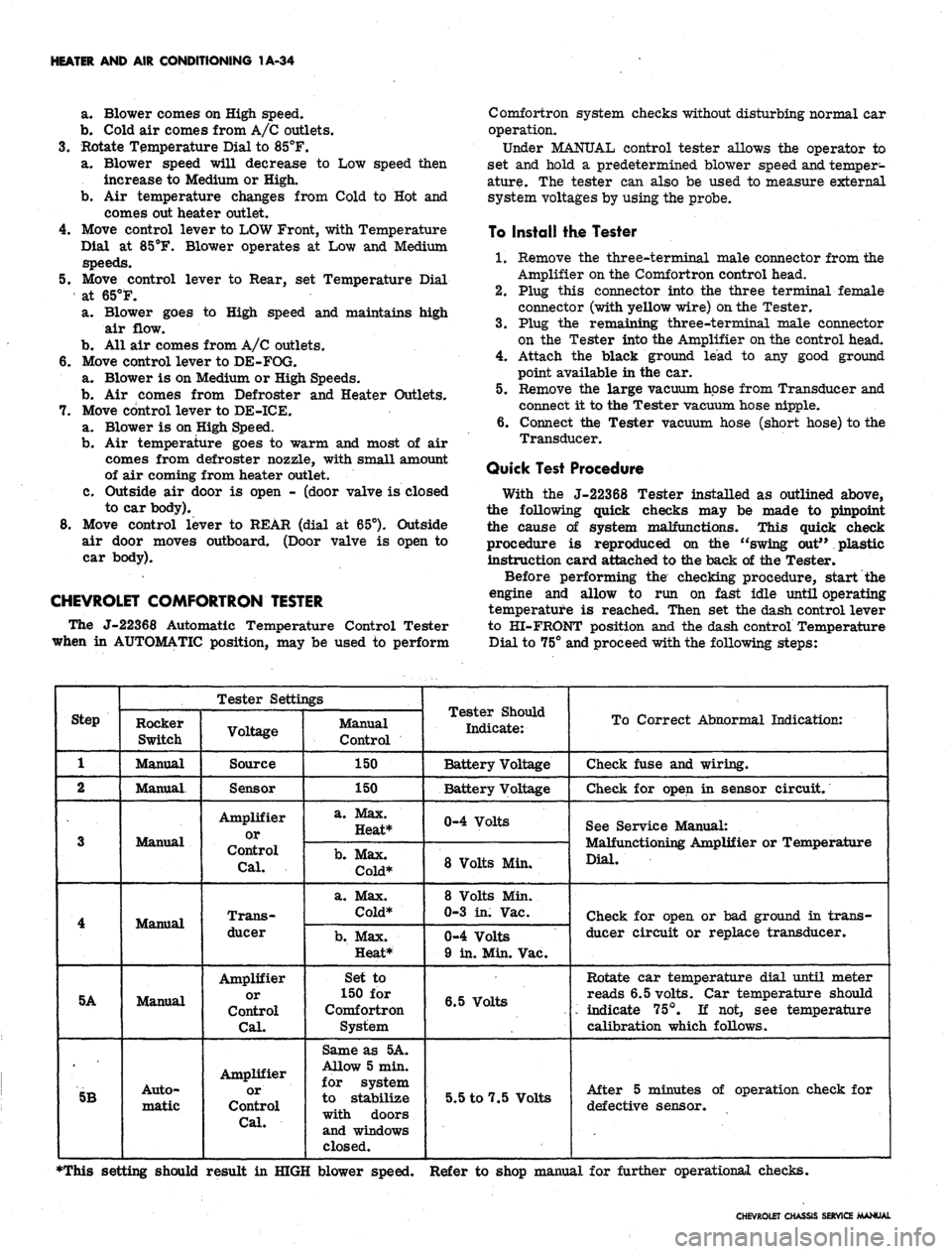
CHEVROLET COMFORTRON TESTER
The J-22368 Automatic Temperature Control Tester
when in AUTOMATIC position, may be used to perform
Comfortron system checks without disturbing normal car
operation.
Under MANUAL control tester allows the operator to
set and hold a predetermined blower speed
and.
temper-
ature. The tester can also be used to measure external
system voltages by using the probe.
To Install the Tester
1.
Remove the three-terminal male connector from the
Amplifier on the Comfortron control head.
2.
Plug this connector into the three terminal female
connector (with yellow wire)
on
the Tester.
3.
Plug the remaining three-terminal male connector
on the Tester into the Amplifier on the control head.
4.
Attach the black ground lead to any good ground
point available in the car.
5.
Remove the large vacuum hose from Transducer and
connect it to the Tester vacuum hose nipple.
6. Connect the Tester vacuum hose (short hose) to the
Transducer.
Quick Test Procedure
With the J-22368 Tester installed as outlined above,
the following quick checks may be made to pinpoint
the cause of system malfunctions. This quick check
procedure is reproduced on the "swing out" plastic
instruction card attached to the back of the Tester.
Before performing the checking procedure, start the
engine and allow to run on fast idle until operating
temperature is reached. Then set the dash control lever
to HI-FRONT position and the dash control Temperature
Dial to 75° and proceed with the following steps:
Step
1
2
3
4
5A
5B
Tester Settings
Rocker
Switch
Manual
Manual.
Manual
Manual
Manual
Auto-
matic
Voltage
Source
Sensor
Amplifier
or
Control
Cal.
Trans-
ducer
Amplifier
or
Control
Cal.
Amplifier
or
Control
Cal.
Manual
Control
150
150
a. Max.
Heat*
b.
Max.
Cold*
a. Max.
Cold*
b.
Max.
Heat*
Set to
150 for
Comfortron
System
Same as 5A.
Allow 5 min.
for system
to stabilize
with doors
and windows
closed.
Tester Should
Indicate:
Battery Voltage
Battery Voltage
0-4 Volts
8 Volts Min.
8 Volts Min.
0-3 in. Vac.
0-4 Volts
9 in. Min. Vac.
6.5 Volts
5.5 to 7.5 Volts
To Correct Abnormal Indication:
Check fuse and wiring.
Check for open in sensor circuit.
See Service Manual:
Malfunctioning Amplifier or Temperature
Dial.
Check for open or bad ground in trans-
ducer circuit or replace transducer.
Rotate car temperature dial until meter
reads 6.5 volts. Car temperature should
'•- indicate 75°. If not, see temperature
calibration which follows.
After 5 minutes of operation check for
defective sensor.
•This setting should result in HIGH blower speed. Refer to shop manual for further operational checks.
CHEVROLET CHASSIS SERVICE MANUAL