steering CHEVROLET CAMARO 1967 1.G Chassis Service Manual
[x] Cancel search | Manufacturer: CHEVROLET, Model Year: 1967, Model line: CAMARO, Model: CHEVROLET CAMARO 1967 1.GPages: 659, PDF Size: 114.24 MB
Page 295 of 659
ENGINE 6-30
c". Install the valve locks and release the compres-
sor tool making sure the locks seat properly in
the upper groove of the valve stem.
NOTE: Grease may be used to hold the locks
in place while releasing the compressor tool.
396 and 427
cu.
in.
Engines
a. Install new valve stem oil seal (coated with oil)
in position over valve guide.
b.
Set the valve spring and damper and valve cap in
place.
c. Compress the spring with Tool J-5892 and install
the valve locks, then release the compressor tool,
making sure the locks seat properly in the groove
of the valve stem.
NOTE: Grease may be used to hold the locks
in place while releasing the compressor tool.
7.
Install spark ,plug, using a new gasket, and torque to
specifications. -
8. Install and adjust valve mechanism as outlined.
CYLINDER HEAD ASSEMBLY
Removal
1.
Remove intake manifold as outlined.
2.
Remove exhaust manifolds as outlined.
3.
Remove valve mechanism as outlined.
4.
Drain cooling system (block).
5.
Remove cylinder head bolts, cylinder head and gas-
ket. Place cylinder head on two blocks of wood to
prevent damage.
Installation
CAUTION: The gasket surfaces on both the
head and the block must be clean of any foreign
ttter and free of nicks or heavy scratches.
Under bolt threads in the block and threads on
Pie cylinder head bolt must be cleaned. (Dirt
will affect bolt torqueT)
1.
On engines using a STEEL gasket, coat both sides of
a new gasket with a good sealer, spread the sealer
thin and even. One method of applying the sealer that
will assure the proper- coat is with the use of a paint
roller. Too much sealer may hold the beads of the
gasket away from the head or block.
CAUTION: Use no sealer on engines using a
composition STEEL ASBESTOS gasket.
2.
Place the gasket in position over the dowel pins with
the bead up.
3.
Carefully guide cylinder head into place over dowel
pins and gasket.
4.
Coat threads of cylinder head bolts with sealing
compound and install finger tight.
5.
Tighten cylinder head bolts a little at a time in the
sequence shown on the torque sequence chart until
the specified torque is reached.
6. Install the exhaust manifold as outlined.
7.
Install the intake manifold as outlined.
8. Install and adjust the valve mechanism as outlined.
OIL
PAN
Removal
Chevrolet
and Camaro
1.
Disconnect battery positive cable.
2.
Disconnect distributor cap from distributor (to pr-e-
vent breaking distributor cap when engine is raised).
3.
Drain radiator, then disconnect lower radiator hose
at water pump and remove oil dip stick and tube
(where necessary). '
4.
Remove fan blade.
5.
Raise vehicle then drain engine oil;
6. Remove through bolts from engine front mounts.
Disconnect and remove starter.
7.
On vehicles equipped with automatic transmissions,
remove converter housing underpan.
8. Disconnect steering rod at idler lever then swing
steering linkage 4pwn for oil pan clearance.
9. Rotate crankshaft untii timing mark on torsional
damper is at 6:00 o'clock position.
10.
Using a suitable jack, and a block of wood to prevent
damaging oil pan, raise engine "enough to insert 2" x
4"
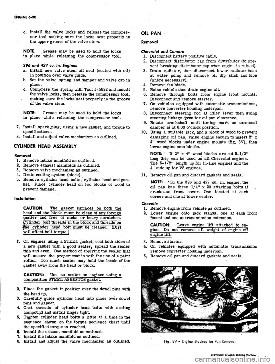
wood blocks under engine mounts (fig. 8V), then
lower engine onto blocks.
NOTE: If 2" x 4" wood blocks are cut 5-1/2"
long they can be used on all Chevrolet engines.
The 5-1/2" length up for In-line engines and the
4"
side up for V8 engines.
11.
Remove oil pan and discard gaskets and seals.
NOTE: -On the 396 and 427 cu. in. engine, the
oil pan has three 1/4" x 20 attaching bolts at ,
crankcase front cover. One located at each
corner and one at lower center.
Chevelle
1.
Remove engine from vehicle as outlined.
2.
Lower engine onto jack stands, one at each front
Tnaount and one at transmission extension.
CAUTION: Leave engine lift attached to en-
gine.
Do not remove all weight of engine off
engine lifET
3.
Remove starter.
4.
On vehicles equipped with automatic transmission
remove converter housing underpan.
5.
Remove oil pan and discard gaskets and seals.
Fig.
8V - Engine Blocked for Pan Removal
CHEVROLET CHASSIS SERVICE MANUAL
Page 296 of 659
ENGINE 6-31
Chevy II
1.
Disconnect battery positive cable.
2.
Drain engine oil.
3.
Disconnect and remove starter.
4 Disconnect steering idler arm bracket at right hand
frame rail and swing steering linkage down for pan
clearance.
5.
Disconnect* exhaust pipes at manifolds and allow
pipes to hang free.
6. Remove oil pan and discard gaskets and seals.
Corvette
1.
Disconnect battery positive cable then remove oil
dipstick and tube.
2.
Raise and support vehicle then drain engine oil.
3.
Remove starter and flywheel underpan.
4.
Disconnect steering linkage idler at frame and lower
the linkage.
5.
Remove oil pan and discard gaskets and seals.
6. On Hi-Performance engines, the oil baffle must
be removed before additional operations can be
performed.
NOTE: On the 427 cu. in. engine, the oil pan
has three 1/4" x 20 attaching bolts at crankcase
front cqver. One located at each corner and one
at lower center.
Installation
1.
Thoroughly clean all gasket sealing surfaces.
NOTE: Use a new pan. gasket set.
2.
Install side gaskets on pan rails, using.gasket sealer
as a retainer.
3.
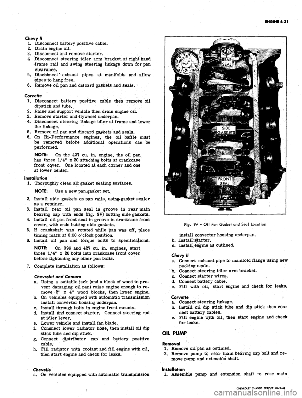
Install rear oil pan seal in groove in rear main
bearing cap with ends (fig. 9V) butting side gaskets.
4.
Install oil pan front seal in groove in .crankcaee front
cover, with ends butting side gaskets.
5.
If crankshaft was rotated while £>an was off, place
timing mark at 6:00 o'clock position.
6. Install oil pan and torque bolts to specifications.
NOTE: On 396 and 427 cu. in. engines, start
three 1/4" x 20 bolts into crankcase front cover
before tightening, any other pan bolts.
7.
Complete installation as follows:
Chevrolet
and Camaro
a. Using a suitable jack (and a block of wood to pre-
vent damaging oil pan) raise engine enough to re-
move 2" x 4" wood blocks, then lower engine.
b.
On vehicles equipped with automatic transmission
install converter housing underpan.
c. Install through bolts in engine front mounts.
d. Install and connect starter. Connect steering rod
at idler lever.
e. Lower vehicle and install fan blade.
f. Cbnnnect lower radiator hose, then install oil dip
stick tube and dip stick.
g. Connect distributor cap and battery positive
cable.
h. Fill radiator with coolant and fill engine with oil,
then start engine and check for leaks.
Chevelle
a. On vehicles equipped with automatic transmission
Fig.
9V - Oil Pan Gasket and Seal Location
install converter housing underpan.
b.
.Install starter.
c. Install, engine as outlined.
Chevy II
a. Connect exhaust pipe to manifold flange using new
packing seals.
b.
Connect steering idler arm bracket.
c. Connect starter wires..
d. Connect battery cable.
e. Fill with oil, start engine and check for leaks.
Corvette
a. Connect steering linkage.
b.
Install oil dip stick tube and dip stick then con-
nect battery cables.
c. Fill engine with oil, then start engine and check
for leaks.
OIL PUMP
Removal
1.
Remove oil pan as outlined.
2.
Remove pump to rear main bearing cap bolt and re-
move pump and extension shaft.
Installation
1.
Assemble pump and extension shaft to rear main
CHEVROLET CHASSIS SERVICE MANUAL
Page 339 of 659
ENGINE-ELECTRICAL 6Y-14
VOLTMETER
WIRING HARNESS
CONNECTOR
Fig.
12c—Field Relay Closing Voltage Test
FIELD RELAY CHECKS AND ADJUSTMENT
To check for a faulty relay proceed as follows:
1.
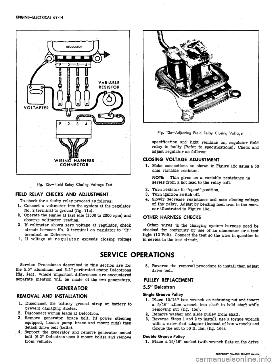
Connect a voltmeter into the system at the regulator
No.
2 terminal to ground (fig. lie).
2.
Operate the engine at fast idle (1500 to 2000 rpm) and
observe voltmeter reading.
3.
If voltmeter shows zero voltage at regulator, check
circuit between No. 2 terminal on regulator to "R"
terminal on Delcotron.
4.
If voltage at regulator exceeds closing voltage
Fig.
13c—Adjusting Field Relay Closing Voltage
specification and light remains on, regulator field
relay is faulty (Refer to specifications). Check and
adjust regulator as follows:
CLOSING VOLTAGE ADJUSTMENT
•1.
Make connections as shown in Figure 12c using a 50
ohm variable resistor.
NOTE: This gives us a variable resistance in
series from a hot lead to the relay coil.
2.
Turn resistor to "open" position.
3.
Turn ignition switch off.
4.
Slowly decrease resistance and note closing voltage
of the relay. Adjust by bending heel iron in the man-
ner illustrated in Figure 13c.
OTHER HARNESS CHECKS
Other wires in the charging system harness need be
checked for continuity by use of an ohmmeter or a test
ligjit (12 Volt). Connect the test so the wire in question is
in series in the test circuit.
SERVICE OPERATIONS
Service Procedures described in this section are for
the 5.5" aluminum and 6.2" perforated stator Delcotrons
(fig. 14c). Where important differences are encountered
separate mention will be made of the two generators.
GENERATOR
REMOVAL AND INSTALLATION
1.
Disconnect the battery ground strap at battery to
prevent damaging diodes.
2.
Disconnect wiring leads at Delcotron.
3.
Remove generator brace bolt, (if power steering
equipped, loosen pump brace and mount nuts) then
detach drive belt (belts).
4.
Support the generator and remove generator mount
bolt (6.2" Delcotron uses 2 mount bolts) and remove
from vehicle.
5.
Reverse the removal procedure to install then adjust
drive belt.
PULLEY REPLACEMENT
5.5" Delcotron
Single Groove Pulley
1.
Place 15/16" box wrench on retaining nut and insert
a 5/16" alien wrench into shaft to hold shaft while
removing nut (fig. 15c).
2.
Remove washer and slide pulley from shaft.
3.
Reverse Steps 1 and
2
to install, use a torque wrench
with a crow-foot adapter (instead of box wrench) and
torque the nut to 50 ft. lbs. (fig. 16c).
Double Groove Pulley
1.
Place a 15/16" socket (with wrench flats on the drive
CHEVROLET CHASSIS SERVICE MANUAL
Page 383 of 659
CLUTCH AND TRANSMISSIONS 7-24
is at the full mark on the dip stick, it is just slightly be-
low the planetary gear unit. If additional oil is added,
bringing the oil level above the full mark, the planetary
unit will run in the oil, foaming and aerating the oil. This
aerated oil carried through the various oil pressure pas-
sages (low servo, reverse servo, clutch apply, converter,
etc.) may cause malfunction of the transmission assem-
bly, resulting in cavitation noise in the converter and
improper band or clutch application. Overheating may
also occur.
If the transmission is found consistently low on oil, a
thorough inspection should be made to find and correct
all external oil leaks.
PERIODIC OIL CHANGE
The transmission oil should be changed periodically as
recommended in Section 0, and whenever transmission is
to be removed from the vehicle for repairs.
1.
Run engine for one minute in neutral prior to chang-
ing.
2.
Be sure vehicle is level or raise from the rear only.
3.
Remove the oil pan drain plug and allow oil to drain
thoroughly into a pan or can.
Replace drain plug and refill with approximately two
quarts of oil specified in Section 0.
NOTE: To refill the transmission, remove dip
stick from oil filler tube and refill transmission
with oil specified in Section 0 using filler tube
and funnel J-4264. Then, after shifting into all
ranges at idle speed to fill all oil passages, the
engine should be run at 800-1000 rpm with the
transmission in Neutral until the oil warms up,
then add oil as required to raise the fluid level
to the full mark on the dip stick. Refill capacity
is approximately 2 qts.
4.
Fig.
1PG - Adjusting Low Band Using J-21848
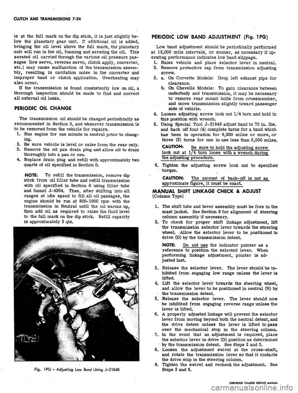
PERIODIC LOW BAND ADJUSTMENT (Fig. 1PG)
Low band adjustment should be periodically performed
at 12,000 mile intervals, or sooner, as necessary if op-
erating performance indicates low band slippage.
1.
Raise vehicle and place selector lever in neutral.
2.
Remove protective cap from transmission adjusting
screw.
3.
a. On Corvette Models: Drop left exhaust pipe for
clearance.
b.
On Chevelle Models: To gain clearance between
underbody and transmission, it may be necessary
to remove rear mount bolts from crossmember,
and move transmission slightly toward passenger
side of vehicle. .
4.
Loosen adjusting screw lock nut 1/4 turn and hold in
this position with wrench.
5.
Using Special Tool J-21848 adjust band to 70 in. lbs.
and back off four (4) complete turns for a band which
has been in operation for 6,000 miles or more,.or
three (3) turns for one in use less than 6,000 miles.
CAUTION: Be sure to hold the adjusting screw
lock nut at 1/4 turn loose with a wrench during"
the.adjusting procedure.
6. Tighten the adjusting screw lock nut to specified
torque.
CAUTION: The amount of back-off is not an
approximate figure, it must be exact.
MANUAL SHIFT LINKAGE CHECK & ADJUST
(Column Type)
1.
The shift tube and lever assembly must be free in the
mast jacket. See Section 9 for alignment of steering
column assembly if necessary.
2.
To check for proper shift linkage adjustment, lift
the transmission selector lever towards the steering
wheel. Allow the selector lever to be positioned in
drive (D) by the transmission detent.
NOTE: Do not use the indicator pointer as a
reference to position the selected lever. When
performing linkage adjustment, pointer is ad-
justed last.
3.
Release the selector lever. The lever should be in-
hibited from engaging low range unless the lever is
lifted.
4.
Lift the selector lever towards the steering wheel,
and allow the lever to be positioned in neutral (N) by
the transmission detent.
5.
Release the selector lever. The lever should now
be inhibited from engaging reverse range unless the
lever is lifted.
6. A properly adjusted linkage will prevent the selector
lever from moving beyond both the neutral detent, and
the drive detent unless the lever is lifted to pass
over the mechanical stop in the steering column.
7.
In the event that an adjustment is required, place
the selector lever in drive (D) position as determined
by the transmission detent. See Steps 2 and 3.
8. Loosen the adjustment swivel at the cross-shaft,
and rotate the transmission lever so that it contacts
the drive stop in the steering column.
9. Tighten the swivel and recheck the adjustment. See
2 and 6.
CHEVROLET CHASSIS SERVICE MANUAL
Page 396 of 659
CLUTCH AND TRANSMISSIONS 7-37
LI.
- LI Range can be selected at any vehicle speed,
and the transmission will shift to second gear
and remain in second until vehicle speed is re-
duced to approximately 40 MPH, .depending on
axle ratio. LI Range position prevents the trans-
mission from shifting out of first gear.
It is very important that any communication concerning
the Turbo Hydra-Matic always contain the transmission
serial number and that all transmission parts returned
to Chevrolet Motor Division always be tagged with the
transmission serial number.
MAINTENANCE AND ADJUSTMENTS
TRANSMISSION FLUID
Transmission fluid level should be checked with trans-
mission warm and selector lever in "P" Park position,
every time engine oil level is checked or as specified in
Section 0 when engine oil is changed.
CAUTION: Since the Turbo Hydra-Matic trans-
mission is very sensitive to oil level, special
precautions should be taken when checking the
oil level, to insure against an overfifE
Transmission fluid should be changed as specified in
Section 0.
FLUID LEVEL INDICATOR
The fluid level indicator is located in the filler pipe at
the right rear corner of the engine. To bring the fluid
level from the add mark to the full mark add 1 pint.
Fluid level should be to the full mark with transmission
at normal operating temperature. With cold fluid the
level should be at the add mark or slightly below.
SHIFT CONTROL LINKAGE ADJUSTMENT
Adjust linkage as shown below and in Figure 2.
1.
The shift tube and lever assembly must be free in the
mast jacket See Section 9 for alignment of steering
column assembly if necessary.
2.
To check for proper shift linkage adjustment, lift the
transmission selector lever towards the steering
wheel. Allow the selector lever to be positioned in
drive (D) by the transmission detent.
NOTE: Do not use the indicator pointer as a
reference to position the selector lever. When
performing linkage adjustment, pointer is ad-
justed last.
3.
Release the selector lever. The lever should be in-
hibited from engaging low range unless the lever is
lifted.
4.
Lift the selector lever towards the steering wheel,
and allow the lever to be positioned in neutral (N) by
the transmission detent.
5.
Release the selector lever. The lever should now be
inhibited from engaging reverse range unless the
lever is lifted.
6. A properly adjusted linkage will prevent the selector
lever from moving beyond both the neutral detent,
and the drive detent unless the lever is lifted to pass
over the mechanical stop in the steering column.
See schematic diagram.
7.
In the event that an adjustment is required, place the
selector lever in drive (D) position as determined by
the transmission detent. See Steps 2 and 3.
8. Loosen the adjustment swivel at the cross-shaft, and
rotate the transmission lever so that it contacts the
drive stop in the steering column.
9. Tighten the swivel and recheck the adjustment. See
Steps 2 and 6. -
l(h Readjust indicator needle if necessary to agree with
the transmission detent" positions. See Section 9.
11.
Readjust neutral safety switch if necessary to pro-
vide the correct relationship to the transmission de-
tent positions. See Section 12.
12.
When properly adjusted the following conditions must
be met by manual operation of the steering column
shift lever:
a. From reverse to drive position travel, the trans-
mission detent feel must be noted and related to
indicated position on dial.
b.
When in drive and reverse positions, pull lever
rearward (towards steering wheel) and then re-
lease. It must drop back into position with no
restrictions.
NEUTRAL SAFETY SWITCH ADJUSTMENT
The neutral safety switch must be adjusted so that the
car will start in the park or neutral position, but will not
start in the other positions. For replacement refer to
Section 12 of this Manual.
DRAINING AND REFILLING TRANSMISSION
Drain oil immediately after operation before it has had
an opportunity to cool.
To drain oil proceed as follows:
1.
Remove bottom pan attaching screws, pan, and gas-
ket.
2.
Remove oil strainer. Remove "O" ring seal from
pick-up pipe and discard.
3.
Discard strainer if dirty.
4.
Install new "O" ring seal on pick-up pipe and install
strainer and pipe assembly.
5.
Thoroughly clean bottom pan.
6.. Affix new gasket to bottom pan with petroleum jelly.
7.
Install bottom pan with attaching screws and torque
to specifications;
8. If only the pan has been removed, pour approximately
7-1/2 pints of fluid into the transmission. If the
valve body has also been removed use 9-1/2 pints.
After a complete overhaul approximately 19 pints
are required. Be sure container, spout, or funnel is
clean.
9. Start engine and let idle (carburetor off fast idle
step).
Place selector lever in P position and apply
hand brake.
10.
With transmission warm (approximately 150°F), add
fluid to bring level to full mark on indicator.
CAUTION: Do not overfill. Foaming will re-
sult.
CHEVROLET CHASSIS SERVICE MANUAL
Page 441 of 659
SECTION
9
STEERING
CONTENTS
OF
THIS SECTION
Standard Steering
9-1
Power Steering
9-33
Special Tools
9-40
STANDARD STEERING
INDEX
Page
General Description 9.x
Maintenance and Adjustments 9.1
Adjustments
........................
9-2
Steering Gear 9-2
Steering Wheel Alignment and Higji
Point Centering. . . . 9-4
Toe-in Adjustment 9-4
Corvette Steering Ratio . . . . 9-4
Component Replacement and Repairs . . . . 9-4
Steering Wheel . . . 9-4
Regular Production 9-4
Simulated Wood . . . . 9-5
Corvette Telescoping 9-5
Steering Coupling . 9-6
Steering Gear . 9-9
Sector Shaft Seal Replacement 9-10
Steering Column 9-10
Removal 9-10
Disassembly—Syncromesh Column 9-12
Page
Assembly—Syncromesh Column . . 9-14
Disassembly—Column Mounted Powerglide
Lever or Floor Shift Column 9-16
Assembly-^Column Mounted Powerglide
Lever or Floor Shift Column g_x7
Disassembly—Tilt Column 9-19
Assembly—Tilt Column 9-21
Disassembly—Standard Corvette Column 9-23
Assembly—Standard Corvette Column 9-25
Disassembly—Corvette Telescoping Column .... 9.26
Assembly—Corvette Telescoping Column 9-27
Installation 9.27
Steering Linkage 9.29
Tie
Rods.
. 9-29
Relay Rod . . 9-31
Idler Arm . . . . 9-31
Pitman Arm. . 9-32
Steering Arms • • • • 9-32
Steering Damper 9-32
GENERAL DESCRIPTION
The regular production steering gear
is the
recirculat-
ing ball type. This gear provides
for
ease
of
handling
by
transmitting forces from worm
to
sector gear through
ball bearings.
The
steering linkage
is of
the relay type,
and extended interval lubrication design, with the pitman
arm connected
to one end of
the relay
rod. The
other
end
of
the
relay
rod is
connected
to an
idler
arm
which
is
connected
to the
frame side rail opposite
the
steering
gear.
Two
adjustable
tie
rods connect
the
relay
rod to
the steering arms.
All passenger
car
models
for 1967 are
equipped with
new energy absorbing steering columns.
The
mast jacket,
shift tube,
and
steering shaft
are
designed
to
collapse
under various front impact conditions.
All new
columns
are
of
this design, including
the
tilt option and telescope
option.
MAINTENANCE
AND
ADJUSTMENTS
The manual steering gear
is
filled
at the
factory with
a
water resistant grease. Seasonal change
of
this lubrica-
tion
is
unnecessary and
the
housing should
not be
drained.
The steering gear lubricant level should
be
checked every
36,000 miles. Whenever required, additions should
be
made using
a
water resistant
EP
chassis lubricant.
Check and fill steering gear
as
follows:
1.
Remove lower
and
outboard cover retaining screws
(fig.
1).
2.
Insert filling device
in
lower screw hole.
3.
Inject lubricant until
it
appears
in
outboard screw
hole; gear
is now
filled
to
correct level.
The steering linkage should
be
lubricated with water
resistant
EP
chassis lubricant every 6,000 miles
or six
months, whichever occurs first. Lubrication points
and
additional information
on the
chassis lubricant
to be
used
can
be
found
in
Section
0 --
General Information
and
Lubrication.
CHEVROLET CHASSIS SERVICE MANUAL
Page 442 of 659

STEERING 9-2
Fig.
1—Cover
Attaching Bolts—Chevy li Shown
ADJUSTMENTS
STEERING
GEAR
Before any adjustments are made to the steering gear
in an attempt to correct such conditions as shimmy,
loose or hard steering etc., a careful check should be
made of front end alignment, shock absorbers, wheel
balance and tire pressure for possible cause.
Correct adjustment of the steering gear is very im-
portant. Perform adjustments following the sequence
listed below,
1.
Remove pitman arm nut and mark relation of pitman
arm position to sector shaft. Remove pitman arm
with Tool J- 6632 as shown in Figure 2.
2.
Loosen the pitman shaft lash adjuster screw locknut
and turn the adjuster screw a few turns in a counter-
clockwise direction (fig. 3). This removes the load
Fig. 2—Removing Pitman Arm
imposed on the worm bearings by the close meshing
of rack and sector teeth. Turn steering wheel gently
in one direction until stopped by gear, then back away
about one turn.
CAUTION: Do not turn steering wheel hard
against stops when steering relay rod is discon-
nected as damage to ball guides may result.
3.
All except Corvette and telescopic columns:
a. Disconnect steering column harness at chassis
wiring connector plug.
b.
Remove horn cap or ornament and using an inch
pound torque wrench and socket on steering wheel
nut, measure torque required to keep the wheel
in motion.
LASH ADJUSTER
SCREW
LOCK NUT
WORM BEARING
ADJUSTER
\
WORM
ADJUSTER
Fig.
3—Steering Gear Adjustment Points
CHEVROLET CHASSIS SERVICE MANUAL
Page 443 of 659
STEERING 9-3
Fig.
4-Checking Wheel PuI!-Corvette
c. If torque does not lie within limits given in speci-
fications at rear of manual, adjustment is
necessary.
4.
Corvette and telescopic columns:
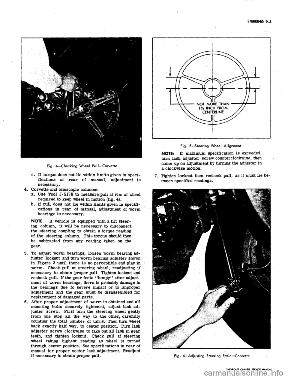
a. Use Tool J-5178 to measure.pull at rim of wheel
required to keep wheel in motion (fig. 4).
b.
If pull does not lie within limits given in specifi-
cations in rear of manual, adjustment of worm
bearings is necessary.
NOTE:
If vehicle is equipped with a tilt steer-
ing column, it will be necessary to disconnect
the steering coupling to obtain a torque reading
of the steering column. This torque should then
be subtracted from any reading taken on the
gear.
5. To adjust worm bearings, loosen worm bearing ad-
juster locknut and turn worm bearing adjuster shown
in Figure 3 until there is no perceptible end play in
worm. Check pull at steering wheel, readjusting: if
necessary to obtain proper pull. Tighten locknut and
recheck pull. If the gear feels "lumpy" after adjust-
ment of worm bearings, there is probably damage in
the bearings due to severe impact or to improper
adjustment and the gear must be disassembled for
replacement of damaged parts.
6. After proper adjustment of worm is obtained and all
mounting bolts securely tightened, adjust lash ad-
juster screw. First turn the steering wheel gently
from one stop all the way to the other, carefully
counting the total number of turns. Then turn wheel
back exactly half way, to center position. Turn lash
adjuster screw clockwise to take out all lash in gear
teeth, and tighten locknut. Check pull at steering
wheel taking highest reading as wheel is turned
through center position. See specifications in rear of
manual for proper sector lash adjustment. Readjust
if necessary to obtain proper pull.
NOT MORE THAN
T/a INCH FROM
CENTERLINE
Fig.
5—Steering Wheel Alignment
NOTE:
If maximum specification is exceeded,
turn las£ adjuster screw counterclockwise, then
come up on adjustment by turning the adjuster in
a clockwise motion.
7. Tighten locknut then recheck pull, as it must lie be-
tween specified readings.
Fig.
6—Adjusting Steering Ratio—Corvette
CHEVROLET CHASSIS SERVICE MANUAL
Page 444 of 659
STEERING 9-4
8. Reassemble pitman arm to sector shaft, lining up
marks made during disassembly. Refer to torque
specifications at rear of manual for correct torque
value.
9. Install horn cap or ornament and connect steering
column harness at chassis connector.
NOTE:
Chevy.n models are equipped with a
shim at the frame to steering gear mounting
bolts.
Shims may be removed or installed as
required for proper steering gear alignment.
STEERING WHEEL ALIGNMENT AND
HIGH POINT CENTERING
1.
Set front wheels in straight ahead position. This can
be checked by driving vehicle a short distance on a
flat surface to determine steering wheel position at
which vehicle follows a straight path.
2.
With front wheels set straight ahead, check position
of mark on wormshaft designating steering gear high
point. This mark should be at the top side of the shaft
at 12 o'clock position and lined up with the mark in
the coupling lower clamp.
3.
If gear has been moved off high point when setting
wheels in straight ahead position, loosen adjusting
sleeve clamps on both left and right hand tie rods,
then turn both sleeves an equal number of turns in
the same direction to bring gear back on high point.
CAUTION: Turning the sleeves an unequal
number of turns or in differential directions will
disturb the toe-in setting of the wheels.
4.
Readjust toe-in as outlined in Section 3 (if necessary).
5. With wheels in a straight ahead position and the
steering gear on highpoint, check the steering wheel
alignment by measuring the distance from each hori-
zontal spoke to the horizontal centerline of the
steering wheel (fig. 5). If the horizontal spokes are
over 1-1/8 inches from the horizontal position the
wheel should be removed and centered. (See steering
wheel removal in this section.)
TOE-IN ADJUSTMENT
Adjust the steering linkage for proper toe-in setting as
outlined in Section 3.
CORVETTE STEERING RATIO (Fig. 6)
The Corvette steering ratio may be changed as follows:
CAUTION: Do not use the rearward hole in the
steering arm with power steering equipment or
interference may result.
1.
Remove tie rod ball stud nut at steering arm and
disconnect tie rod from steering arm.
2.
Move tie rod end to forward hole for 17.6:1 ratio
(fast ratio) or rear hole for 20.2:1 ratio (standard
ratio).
3.
Install tie rod stud nut and tighten securely. Repeat
operation on opposite steering arm.
COMPONENT REPLACEMENT AND REPAIRS
STEERING WHEEL
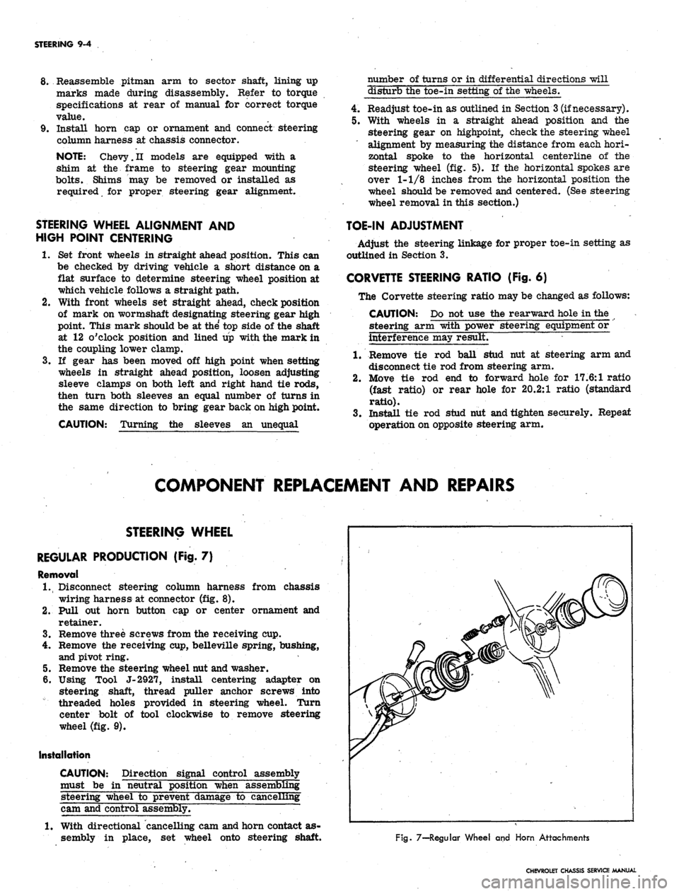
REGULAR PRODUCTION (Fig. 7)
Removal
1.
Disconnect steering column harness from chassis
wiring harness at connector (fig. 8).
2.
Pull out horn button cap or center ornament and
retainer.
3.
Remove three screws from the receiving cup.
4.
Remove the receiving cup, belleville spring, bushing,
and pivot ring.
5. Remove the steering wheel nut and washer.
6. Using Tool J-2927, install centering adapter on
steering shaft, thread puller anchor screws into
threaded holes provided in steering wheel. Turn
center bolt of tool clockwise to remove steering
wheel (fig. 9).
Installation
CAUTION: Direction signal control assembly
must be in "neutral position when assembling
steering wheel to prevent damage to cancelling
cam and control assembly.
1.
With directional cancelling cam and horn contact as-
sembly in place, set wheel onto steering shaft.
Fig. 7—-Regular Wheel and Horn Attachments
CHEVROLET CHASSIS SERVICE MANUAL
Page 445 of 659
STEERING 9-5
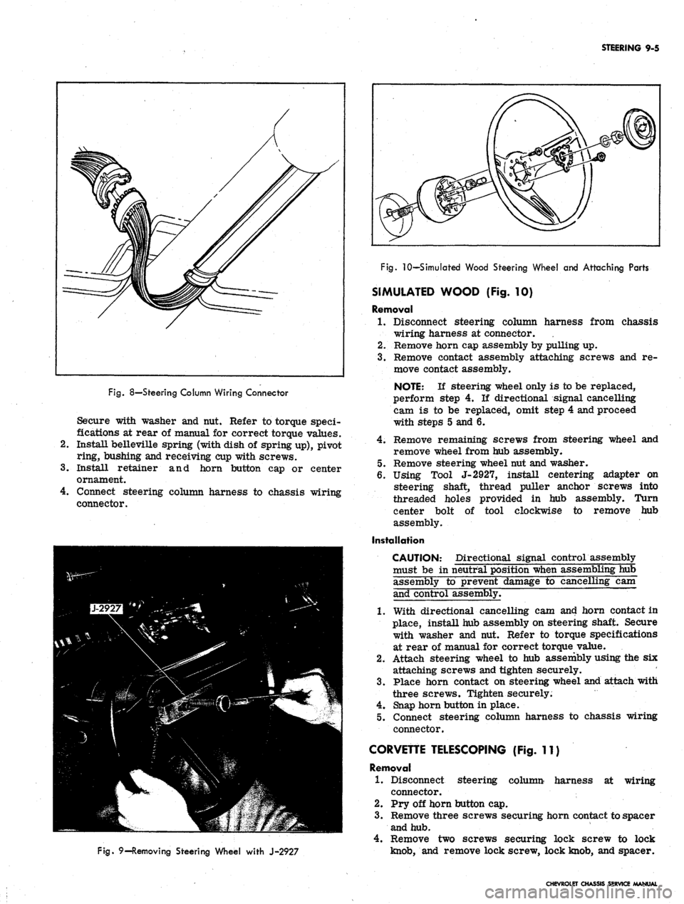
Fig.
8—Steering Column Wiring Connector
Secure with washer and nut. Refer to torque speci-
fications at rear of manual for correct torque values.
Install belleville spring (with dish of spring up), pivot
ring, bushing and receiving cup with screws.
Install retainer and horn button cap or center
ornament.
Connect steering column harness to chassis wiring
connector.
Fig.
9—Removing Steering Wheel with J-2927
Fig.
10—Simulated Wood Steering Wheel and Attaching Parts
SIMULATED WOOD (Fig. 10)
Removal
1.
Disconnect steering column harness from chassis
wiring harness at connector.
2.
Remove horn cap assembly by pulling up.
3.
Remove contact assembly attaching screws and re-
move contact assembly.
NOTE:
If steering wheel only is to be replaced,
perform step 4. If directional signal cancelling
cam is to be replaced, omit step 4 and proceed
with steps 5 and 6.
4.
Remove remaining screws from steering wheel and
remove wheel from hub assembly.
5. Remove steering wheel nut and washer.
6. Using Tool J-2927, install centering adapter on
steering shaft, thread puller anchor screws into
threaded holes provided in hub assembly. Turn
center bolt of tool clockwise to remove hub
assembly.
Installation
CAUTION: Directional signal control assembly
must be in neutral position when assembling hub
assembly to prevent damage to cancelling cam
and control assembly.
1.
With directional cancelling cam and horn contact in
place, install hub assembly on steering shaft. Secure
with washer and nut. Refer to torque specifications
at rear of manual for correct torque value.
2.
Attach steering wheel to hub assembly using the six
attaching screws and tighten securely.
3.
Place horn contact on steering wheel and attach with
three screws. Tighten securely.
4.
Snap horn button in place.
5. Connect steering column harness to chassis wiring
connector.
CORVETTE TELESCOPING (Fig. 11)
Removal
1.
Disconnect steering column harness at wiring
connector.
2.
Pry off horn button cap.
3.
Remove three screws securing horn contact to spacer
and hub.
4.
Remove two screws securing lock screw to lock
knob,
and remove lock screw, lock knob, and spacer.
CHEVROLET CHASSIS SERVICE MANUAL