tire type CHEVROLET CAMARO 1967 1.G Chassis Workshop Manual
[x] Cancel search | Manufacturer: CHEVROLET, Model Year: 1967, Model line: CAMARO, Model: CHEVROLET CAMARO 1967 1.GPages: 659, PDF Size: 114.24 MB
Page 18 of 659
LUBRICATION 0-16
Every 12,000 miles (more frequently*, depending on
severity of service, if vehicle is used to pull trailers,
carry full loads during high ambient temperatures,
operate in mountainous terrain or operate under other
severe conditions--Remove fluid from the transmission
sump and add one and a half quarts of fresh fluid for
Camaro and Chevy II and two quarts for Chevrolet,
Chevelle, and Corvette. Operate transmission through all
ranges and check fluid level as described above.
•Except if vehicle is equipped with transmission pro-
vided in heavy duty service options. If so equipped,
drain converter and pump every 12,000 miles and add
approximately seven and a half quarts of fresh fluid
for Chevy II and nine quarts for Chevrolet and Chevelle.
TURBO HYDRA-MATIC
Lubrication. recommendations for the Turbo Hydra-
Matic are the same as outlined for the Powerglide
transmission except for fluid capacity and filter change
listed below.
After checking transmission fluid level it is important
that the dip stick be pushed all the way into the fill tube.
Every 12,000 miles — after removing fluid from the
transmission sump, approximately 7 1/2 pints of fresh
fluid will be required to return level to proper mark on
the dip stick.
Every 24,000 miles, or at every other fluid change--
the transmission sump strainer should be replaced.
FRONT WHEEL BEARINGS
It is necessary to remove the wheel and hub assembly
to lubricate the bearings. The bearing assemblies should
be cleaned before repacking with lubricant. Do not pack
the hub between the inner and outer bearing assemblies
or the hub caps, as this excessive lubrication results in
the lubricant working out into the brake drums and
linings.
Front wheels of all passenger car models are equipped
with tapered roller bearings and should be packed with a
high melting point water resistant front wheel bearing
lubricant whenever wheel and hub are removed.
CAUTION: "Long fibre" or "viscous" type
lubricant should not be used. Do not mix wheel
bearing lubricants. Be sure to thoroughly clean
bearings and hubs of all old lubricant before
repacking.
The proper adjustment of front wheel bearings is one
of the important service operations- that has a definite
bearing on safety. A car with improperly adjusted front
wheel bearings lacks steering stability, has a tendency to
wander or shimmy and may have increased tire wear.
The adjustment of these bearings is very critical. The
procedure is covered in Section 3 of this manual under
Front Wheel Bearings—Adjust,
MANUAL STEERING GEAR
Check lubricant level every 36,000 miles. If required,
add EP Chassis Lubricant.
POWER STEERING
On models equipped with power steering gear, check
fluid at operating temperature in pump reservoir. Add
GM Power Steering Fluid, or, if this is not available, use
Automatic Transmission Fluid "Type A" bearing the
mark AQ-ATF followed by a number and the suffix letter
'A'
to bring level to full mark on dip stick.
AIR CONDITIONING
After the first 6,000 miles, check all hose clamp
connections for proper tightness.
Every 6,000 miles check sight glass under the hood,
after the system has been in operation for several
minutes. Sight glass should be clear but may, during
milder weather, show traces of bubbles. Foam or dirt
indicate a leak which should be repaired immediately.
BRAKE MASTER CYLINDER
Check level every 6,000 miles and maintain 1/4" below
lowest edge of each filler opening with GM Hydraulic
Brake Fluid Supreme No. 11.
PARKING BRAKE
Every 6,000 miles, apply water resistant lube to park-
ing brake cable, cable guides and at all operating links
and levers.
CLUTCH CROSS-SHAFT
Periodic lubrication of the clutch cross shaft is not
required. At 36,000 miles or sooner, if necessary;
remove plug, install lube fitting and apply CHASSIS
LUBRICANT.
CHASSIS LUBRICATION
For chassis lubrication, consult the lubrication chart.
It shows the points to be lubricated and how often the
lubricant should be applied.
The term "chassis lubricant" as used in this manual,
describes a water resistant EP chassis grease designed
for application by commercial pressure gun equipment.
CHEVROLET CHASSIS SERVICE MANUAL
Page 113 of 659
CORVETTE BODY
1B-6
ASH TRAY
SET SCREW
(PART
OF
KNOB)
TENSION
ADJUSTING
SCREWS
Fig.
8—Console Trim
cracks",
the
windshield opening must
be
carefully
checked
for
irregularities
and
deformation.
To
check
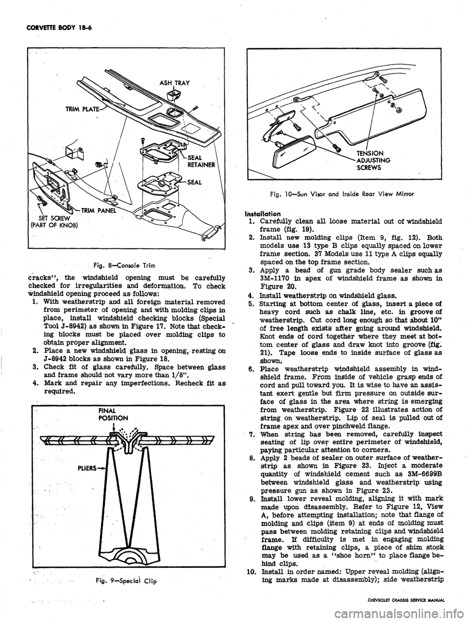
windshield opening proceed
as
follows:
1.
With weatherstrip
and all
foreign material removed
from perimeter
of
opening and with molding clips
in
place, install windshield checking blocks (Special
Tool J-8942)
as
shown in Figure 17. Note that check-
ing blocks must
be
placed over molding clips
to
obtain proper alignment.
2.
Place
a new
windshield glass
in
opening, resting on
J-8942 blocks
as
shown in Figure
18.
3.
Check
fit of
glass carefully. Space between glass
and frame should not vary more than 1/8".
4.
Mark
and
repair
any
imperfections. Recheck
fit as
required.
Fig.
9—Special Clip
Fig.
10—Sun Visor and Inside Rear View Mirror
Installation
1.
Carefully clean
all
loose material
out of
windshield
frame
(fig. 19).
2.
Install
new
molding clips (Item
9, fig. 12).
Both
models
use 13
type
B
clips equally spaced on lower
frame section.
37
Models use 11 type A clips equally
spaced on the top frame section.
3.
Apply
a
bead
of gun
grade body sealer such
as
3M-1170
in
apex
of
windshield frame
as
shown
in
Figure
20.
4.
Install weatherstrip on windshield glass.
5. Starting
at
bottom center
of
glass, insert
a
piece
of
heavy cord such
as
chalk line,
etc. in
groove
of
weatherstrip.
Cut
cord long enough so that about 10"
of free length exists after going around windshield.
Knot ends
of
cord together where they meet at bot-
tom center
of
glass
and
draw knot into groove
(fig.
21).
Tape loose ends
to
inside surface
of
glass
as
shown.
6. Place weatherstrip windshield assembly
in
wind-
shield frame. From inside
of
vehicle grasp ends
of
cord and pull toward you.
It is
wise to have an assis-
tant exert gentle
but
firm pressure
on
outside sur-
face
of
glass
in the
area where string
is
emerging
from weatherstrip. Figure
22
illustrates action
of
string
on
weatherstrip.
Lip of
seal
is
pulled out of
frame apex and over pinchweld flange.
7. When string
has
been removed, carefully inspect
seating
of lip
over entire perimeter
of
windshield,
paying particular attention to corners.
8. Apply
2
beads
of
sealer on outer surface
of
weather-
strip
as
shown
in
Figure
23.
Inject
a
moderate
quantity
of
windshield cement such
as
3M-6699B
between windshield glass
and
weatherstrip using
pressure gun
as
shown
in
Figure
23.
9. Install lower reveal molding, aligning
it
with mark
made upon disassembly. Refer
to
Figure
12,
View
A, before attempting installation; note that flange
of
molding
and
clips (item
9) at
ends
of
molding must
pass between molding retaining clips and windshield
frame.
li
difficulty
is met in
engaging molding
flange with retaining clips,
a
piece
of
shim stock
may
be
used
as a
"shoe horn"
to
place flange be-
hind clips.
10.
Install
in
order named: Upper reveal molding (align-
ing marks made
at
disassembly); side weatherstrip
CHEVROLET CHASSIS SERVICE MANUAL
Page 151 of 659
CORVETTE BODY 1B-44
VIEW A
VIEW B
Fig.
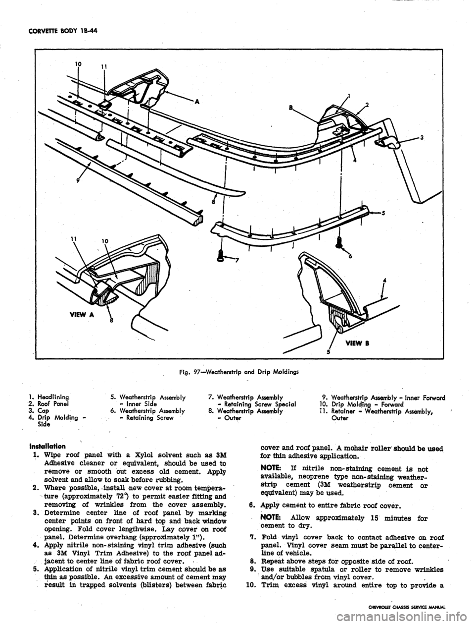
97—Weatherstrip and Drip Moldings
1.
Headlining
2.
Roof Panel
3. Cap
4.
Drip Molding -
Side
5. Weatherstrip Assembly
- Inner Side
6. Weatherstrip Assembly
- Retaining Screw
7. Weatherstrip Assembly
- Retaining Screw Special
8. Weatherstrip Assembly
- Outer
9. Weatherstrip Assembly - Inner Forward
10.
Drip Molding - Forward
11.
Retainer - Weatherstrip Assembly,
Outer
Installation
1.
Wipe roof panel with a Xylol solvent such as 3M
Adhesive cleaner or equivalent, should be used to
remove or smooth but excess old cement. Apply
solvent and allow to soak before rubbing.
2.
Where possible, install new cover at room tempera-
ture (approximately 72 s) to permit easier fitting and
removing of wrinkles from the cover assembly.
3.
Determine center line of roof panel by marking
center points on front of hard top and back window
opening. Fold cover lengthwise. Lay cover on roof
panel. Determine overhang (approximately 1").
4.
Apply nitrile non-staining vinyl trim adhesive (such
as 3M Vinyl Trim Adhesive) to the ropf panel ad-
jacent to center line of fabric roof cover. *
5V Application of nitrile vinyl trim cement should be as
thin as possible. An excessive amount of cement may
result in trapped solvents (blisters) between fabric
cover and roof panel. A mohair roller should be used
for thin adhesive application.
NOTE:
If nitrile non-staining cement is not
available, neoprene type non-staining weather-
strip cement (3M weatherstrip cement or
equivalent) may be used.
6. Apply cement to entire fabric roof cover.
NOTE:
Allow approximately 15 minutes for
7.
cement to dry.
Fold vinyl cover back to contact adhesive on roof
panel. Vinyl cover seam must be parallel to center-
line of vehicle.
8. Repeat above steps for opposite side of
roof.
9. Use suitable spatula or roller to remove wrinkles
and/or bubbles from vinyl cover.
10.
Trim excess vinyl around entire top to provide a
CHEVROLET CHASSIS SERVICE MANUAL
Page 169 of 659
FRONT SUSPENSION 3-5
FRONT END ALIGNMENT
Front end alignment, that is alignment of the inter-
related steering components of the front suspension sys-
tem, must be correctly maintained to assure ease and
stability of steering and satisfactory tire life.
Alignment Preliminary Steps
Several different types of machines are available for
checking all the factors of front end alignment. The in-
structions furnished with each particular machine should
be followed. In all cases, however, checks should be
made with the vehicle level and at curb weight.
Since steering complaints are not always the result of
improper alignment a check should be made to see if any
of the following conditions exist. Any such conditions
should be corrected before proceeding further.
1.
Steering gear loose or improperly adjusted.
2.
Steering gear housing loose at frame.
3.
Excessive wear or play in spherical joints or steer-
ing shaft coupling.
4.
Tie rod or steering connections loose.
5.
Improper front spring heights.
6. Unbalanced or underinflated tires.
7.
Improperly adjusted wheel bearings.
8. Shock absorbers not operating properly.
Wheel alignment should always be made with the vehi-
cle rolled forward taking out any slack in the same man-
ner as when the vehicle is traveling forward.
Caster and Camber Adjustment
NOTE: Before adjusting caster and camber
angles, the front bumper should be raised and
quickly released to allow car to return to its
normal height.
Chevelle, Camaro and Corvette
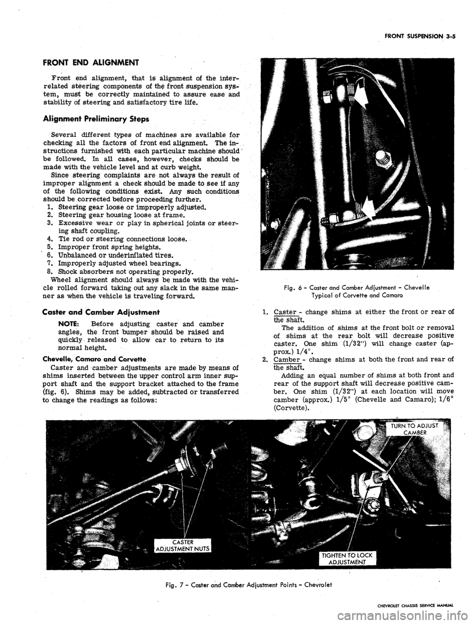
Caster and camber adjustments are made by means of
shims inserted between the upper control arm inner sup-
port shaft and the support bracket attached to the frame
(fig. 6). Shims may be added, subtracted or transferred
to change the readings as follows:
Fig.
6 - Caster and Camber Adjustment - Chevelle
Typical of Corvette and Camaro
Caster - change shims at either the front or rear of
the shaft.
The addition of shims at the front bolt or removal
of shims at the rear bolt will decrease positive
caster. One shim (1/3 2") will change caster (ap-
prox.) 1/4°.
Camber - change shims at both the front and rear of
the shaft.
Adding an equal number of shims at both front and
rear of the support shaft will decrease positive cam-
ber. One shim (1/32") at each location will move
camber (approx.) 1/5° (Chevelle and Camaro); 1/6°
(Corvette).
TIGHTEN TO LOCK
ADJUSTMENT
Fig.
7 - Caster and Camber Adjustment Points - Chevrolet
CHEVROLET CHASSIS SERVICE MANUAL
Page 182 of 659
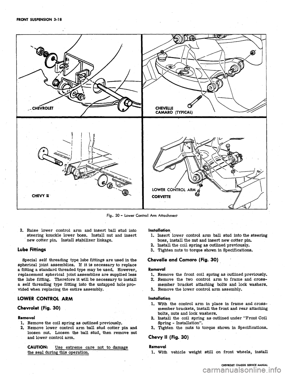
FRONT SUSPENSION 3-18
CHEVROLET
CHEVELLE
CAMARO (TYPICAL)
CHEVY U
LOWER CONTROL ARM
CORVETTE
Fig.
30 - Lower Control Arm Attachment
2.
Raise lower control arm and insert ball stud into
steering knuckle lower boss. Install nut and insert
new cotter pin. Install stabilizer linkage.
Lube Fittings
Special self threading type lube fittings are used in the
spherical joint assemblies. If it is necessary to replace
a fitting a standard threaded type may be used. However,
replacement spherical joint assemblies are supplied less
the lube fitting. Therefore it will be necessary to install
a self threading type fitting into the untapped hole pro-
vided when replacing the entire assembly.
LOWER CONTROL ARM
Chevrolet (Fig. 30)
Removal
1.
Remove the coil spring as outlined previously.
2.
Remove lower control arm ball stud cotter pin and
loosen nut. Loosen the ball stud, then remove nut
and lower control arm.
CAUTION: Use extreme care not to damage
the seal during this operation.
Installation
1.
Insert lower control arm ball stud into the steering
boss,
install the nut and insert new cotter pin.
2.
Install the coil spring as outlined previously.
3.
Tighten nuts to torque shown in Specifications.
Chevelle and Camaro (Fig. 30)
Removal
1.
Remove the front coil spring as outlined previously.
2;
Remove the two control arm to frame and cross-
member bracket attaching bolts and lock washers.
3.
Remove the lower control arm assembly.
Installation
1.
With the control arm in place in frame and cross-
member brackets, install the front and rear attaching
bolts,
nuts and lock washers.
2.
Install the coil spring as outlined under "Front Coil
Spring - Installation".
3.
Tighten the nuts to torque shown in Specifications.
Chevy II (Fig. 30)
Removal
1.
With vehicle weight still on front wheels, install
CHEVROLET CHASSIS SERVICE MANUAL
Page 186 of 659
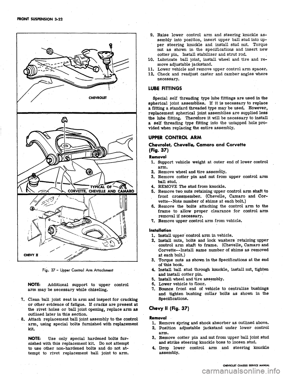
FRONT SUSPENSION
3-22
CHEVROLET
s-L 1 \
TYPICAL
OF
-^-x ^K CORVETTE, CHEVELLE AND CAMARO
CHEVY n
Rg.
37 - Upper Control Arm Attachment
NOTE:
Additional support to upper control
arm may be necessary while chiseling.
7. Clean ball joint seat in arm and inspect for cracking
or other evidence of fatigue. If cracks are present at
the rivet holes or ball joint opening, replace arm as
outlined later in this section.
8. Attach replacement ball joint assembly to the control
arm, using special bolts furnished with replacement
kit.
NOTE:
Use only special hardened bolts fur-
nished with this replacement kit. Do not attempt
to use other non-hardened bolts and do not at-
tempt to rivet replacement ball joint to arm.
9. Raise lower control arm and steering knuckle as-
sembly into position, insert upper ball stud into up-
per steering knuckle and install stud nut. Torque
nut as shown in the specifications and insert new
cotter pin. Install stabilizer and strut rod.
10.
Lubricate ball joint, install wheel and tire and re-
move adjustable jackstand.
11.
Lower vehicle and remove upper control arm spacer.
12.
Check and readjust caster and camber angles where
necessary.
LUBE FITTINGS
Special self threading type lube fittings are used in the
spherical joint assemblies. If it is necessary to replace
a fitting a standard threaded type may be used. However,
replacement spherical joint assemblies are supplied less
the lube fitting. Therefore it will be necessary to install
a self threading type fitting into the untapped hole pro-
vided when replacing the entire assembly.
UPPER CONTROL ARM
Chevrolet, Chevelle, Camaro and Corvette
(Fig.
37)
Removal
1.
Support vehicle weight at outer end of lower control
arm.
2.
Remove wheel and tire assembly.
3.
Remove cotter pin and nut from upper control arm
ball stud. ,
4.
REMOVE The stud from knuckle.
5. Remove two nuts retaining upper control arm shaft to
front crossmember. (Chevelle, Camaro and Cor-
vette—Note number of shims at each bolt.)
6. Remove the bolts attaching the control arm to the
frame to allow proper clearance for control arm
removal if necessary.
7. Remove upper control arm from vehicle.
Installation
1.
Install upper control arm in vehicle.
2.
Install nuts, bolts and lock washers retaining upper
control arm shaft to frame. (Chevelle, Camaro and
Corvette—Install same number of shims as removed
at each bolt.)
3.
Torque nuts as shown in the Specifications at the end
of this book.
4.
Install ball stud through knuckle, install nut, tighten
and install cotter pin.
5. Install wheel and tire assembly.
6. Lower vehicle to floor.
7. Bounce front end of vehicle to centralize bushings
and tighten bushing collar bolts as shown in the
Specifications.
Chevy II (Fig. 37)
Removal
1.
Remove spring and shock absorber as outlined above.
2.
Position adjustable jackstand under lower control
arm.
3.
Remove cotter pin and nut from upper ball joint stud
and strike steering knuckle boss to loosen stud.
4.
Drop lower control arm and steering knuckle
assembly.
CHEVROLET CHASSIS SERVICE MANUAL
Page 219 of 659
REAR SUSPENSION AND DRIVE LINE 4-29
REAR AXLE NOISE DIAGNOSIS
Mechanical failures of the rear axle are relatively
simple to locate and correct. Noise in a rear axle is a
little more difficult to diagnose and repair. One of the
most essential parts of rear axle service is proper
diagnosis.
Ail rear axles are noisy to a certain degree. The
action of transmitting the high engine torque through a
90° turn reducing propeller shaft speed produces noise
in rear axles. This point establishes the need for a line
between normal and abnormal or unacceptable axle
noises.
Slight axle noise heard only at a certain speed or under
remote conditions must be considered normal. Axle noise
tends to "peak" at varying speeds and the noise is in no
way indicative of trouble in the axle.
If noise is present in an objectionable form, loud or at
all speeds, an effort should be made to isolate the noise
as being in one particular unit of the vehicle. Axle noise
is often confused with other noises such as tire noise,
transmission noise, propeller shaft vibration and uni-
versal joint noise. Isolation of the noise as in any one
unit requires skill and experience. An attempt to elimini-
ate a slight noise may baffle even the best of diagnos-
ticians. Such practices as raising tire pressure to
eliminate tire noise, listening for the noise at varying
speeds and on drive, float and coast, and under proper
highway conditions, turning the steering wheel from left
to right to detect wheel bearing noise, will aid even the
beginner in detecting alleged axle noises. Axle noises
fall into two categories: gear noise and bearing noise.
GEAR NOISE
Abnormal gear noise can be recognized since it pro-
duces a cycling pitch and will be very pronounced in the
speed range at which it occurs, appearing under either
"drive," "float" or "coast" conditions. Gear noise
tends to peak in a narrow speed range or ranges, while
bearing noise will tend to remain constant in pitch. Ab-
normal gear noise is rare and usually originates from
the scoring of the ring gear and pinion teeth as a result
of insufficient or improper lubrication in new assemblies.
Side gears seldom give trouble as they are used only
when the rear wheels travel at different speeds.
BEARING NOISE
Defective bearings will always produce a whine that is
constant in pitch and varies with vehicle speed. This fact
will allow you to distinguish between bearing noise and
gear noise.
1.
Pinion bearing noise resulting from a bearing failure
can be identified by a constant rough sound. Pinion
bearings are rotating at a higher speed than differen-
tial side bearings or axle shaft bearings. This
particular noise can be picked up best by testing the
car on a smooth road (black top). However, care
should be taken not to confuse tire noise with bear-
ing or gear noise. If any doubt exists, tire treads
should be examined for irregularities that would
produce such noise.
2.
Wheel bearing noise may be confused with rear axle
noise. To differentiate between wheel bearings and
rear axle, drive the vehicle on a smooth road at
medium-low speed. With traffic permitting, turn
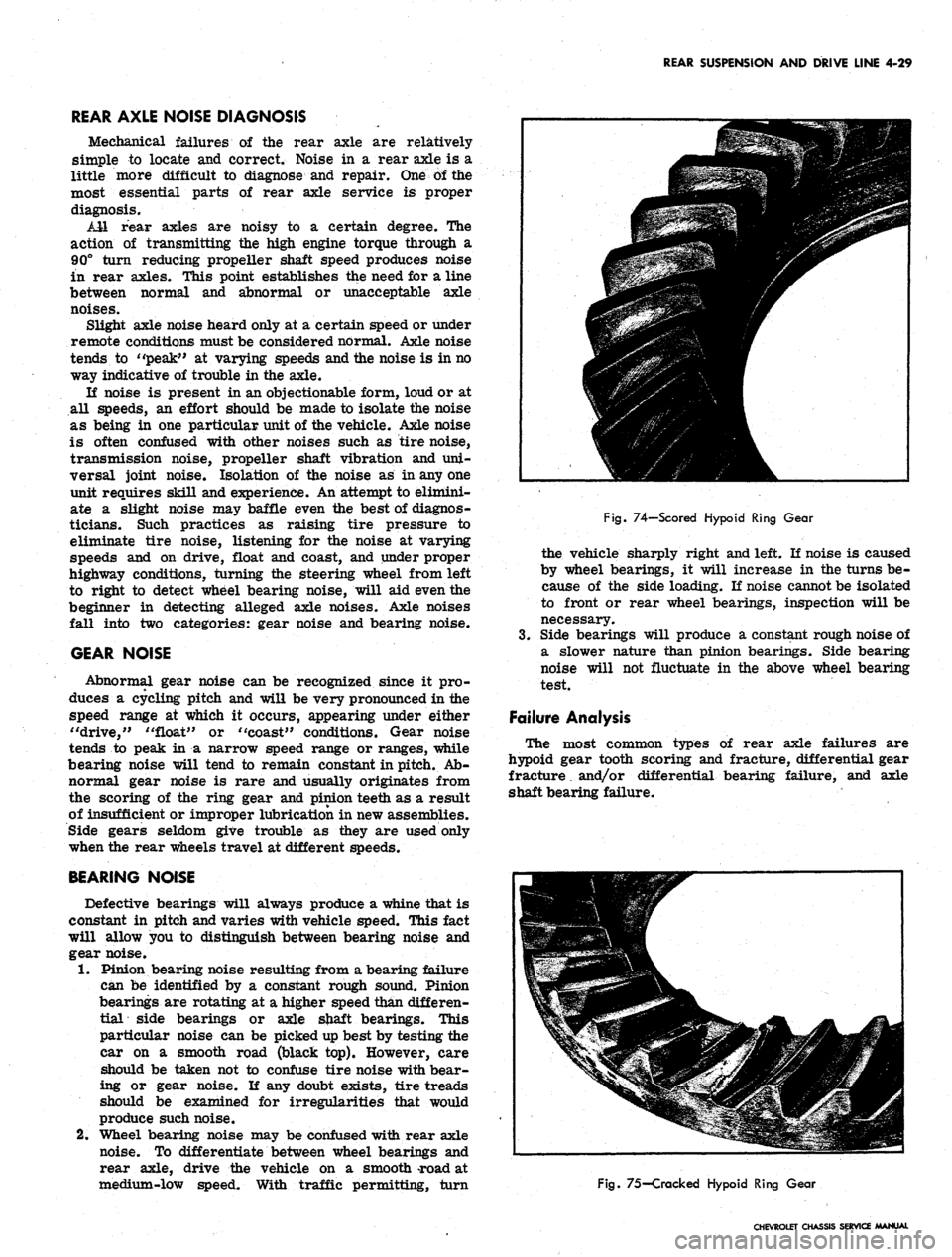
Fig.
74—Scored Hypoid Ring Gear
the vehicle sharply right and left. If noise is caused
by wheel bearings, it will increase in the turns be-
cause of the side loading. If noise cannot be isolated
to front or rear wheel bearings, inspection will be
necessary.
3.
Side bearings will produce a constant rough noise of
a slower nature than pinion bearings. Side bearing
noise will not fluctuate in the above wheel bearing
test.
Failure Analysis
The most common types of rear axle failures are
hypoid gear tooth scoring and fracture, differential gear
fracture. and/or differential bearing failure, and axle
shaft bearing failure.
Fig.
75-Cracked Hypoid Ring Gear
CHEVROLET CHASSIS SERVICE MANUAL
Page 227 of 659
REAR SUSPENSION AND DRIVE LINE 4-37
9. Connect spring end link bolts as outlined under
Spring--Installation, in this section.
10.
Remove filler plug, located on right side of cover,
and fill -with hypoid lubricant to level of filler hole.
11.
Lower vehicle and road test for leaks, noise and
general performance.
POSITRACTION DIFFERENTIAL UNIT
The optionally available Positraction differential unit
is installed in the conventional carrier to replace the
standard differential unit.
Service procedures for the Positraction equipped axle
are the same as on a conventional axle except for the.
operations listed below.
On the Vehicle Check
If vehicle is equipped with a manual transmission, shift
transmission into neutral.
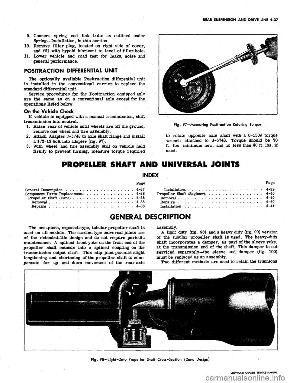
1.
Raise rear of vehicle until wheels are off the ground,
remove one wheel and tire assembly.
2.
Attach Adapter J-5748 to axle shaft flange and install
a
1/2-13
bolt into adapter (fig. 97).
3.
With wheel and tire assembly still on vehicle held
firmly to prevent turning, measure torque required
Fig.
97—Measuring Positraction Rotating Torque
to rotate opposite axle shaft with a 0-150# torque
wrench attached to J-5748. Torque should be 70
ft.
lbs. minimum new, and no less than 40 ft. lbs. if
used.
PROPELLER SHAFT AND UNIVERSAL JOINTS
INDEX
Page
Page
General Description 4-37
Component Parts Replacement. 4-38
Propeller Shaft (Dana) 4-38
Removal 4-38
Repairs 4-38
Installation 4-39
Propeller Shaft (Saginaw) 4-40
Removal 4-40
Repairs 4-40
Installation 4-41
GENERAL DESCRIPTION
The one-piece, exposed-type, tubular propeller shaft is
used on all models. The cardon-type universal joints are
of the extended-life design and do not require periodic
maintenance. A splined front yoke on the front end of the
propeller shaft extends into a splined coupling on the
transmission output shaft. This slip joint permits slight
lengthening and shortening of the propeller shaft to com-
pensate for up and down movement of the rear axle
assembly.
A light duty (fig. 98) and a heavy duty (fig. 99) version
of the tubular propeller shaft is used. The heavy-duty
shaft incorporates a damper, as part of the sleeve yoke,
at the transmission end of the shaft. This damper is not
serviced separately—the sleeve and damper (fig. 100)
must be replaced as an assembly.
Two different methods are used to retain the trunnions
Fig.
98—Light-Duty Propeller Shaft Cross-Section (Dana Design)
CHEVROLET CHASSIS SERVICE MANUAL
Page 234 of 659
BRAKES
SECTION 5
CONTENTS OF THIS SECTION
Duo Servo Brakes
Disc Brakes
Page
5-1 Power Brakes
5-24 Special Tools
Page
5-31
5-32
DUO-SERVO BRAKES
INDEX
Page
General Description 5-1
Maintenance and Adjustments 5-3
Hydraulic Brake Fluid .. . 5-3
Bleeding Hydraulic System 5-3
Pressure Bleeding 5-3
Manual Bleeding 5_4
Push Rod to Main Cylinder Clearance 5-5
Hydraulic Brake Lines 5-5
Hydraulic Brake Hose 5-5
Hydraulic Brake Tubing 5-6
Brake Adjustment. .................... 5-7
Service Brake 5-7
Parking Brake 5-8
Component Replacement and Repairs 5-9
Parking Brake - Chevrolet, Chevelle and
Camaro 5^9
Pedal Assembly 5-9
Front Cable ,. . . 5-9
Center Cable 5-9
Rear Cables. . 5-9
Parking Brake - Chevy n 5-9
Lever Assembly 5-9
Idler Lever 5-11
Front Cable 5-11
Rear Cable . . ; 5-12
Parking Brake - Corvette 5-13
Lever Assembly . . . . 5-13
Front Cable 5-14
Rear Cable . . 5-14
Brake Pedal 5-15
Shoes and Linings 5-16
Organic 5-16
Metallic 5-17
Main Cylinder 5-18
Wheel Cylinders 5-21
Anchor Pin 5-22
Front Wheel 5-22
Rear Wheel 5-22
Brake Drums • 5-22
Brake Pipe Distribution and Switch Assembly . . . . . 5-23
Camaro Pressure Regulator Valve 5-23
GENERAL DESCRIPTION
All 1967 models are equipped with a new split brake
system as a safety feature. If a wheel cylinder or brake
line should fail at either the front end or rear end of
the vehicle, the operator can still bring the vehicle to
a controlled stop. The system is designed with separate
hydraulic systems for the front and rear brake using
a dual master cylinder (fig. 1). The design of the master
cylinder is similar to that used on the 1966 Corvette
in that it has two entirely separate reservoirs and outlets
in a common body casting. The front reservoir and outlet
is connected to the front wheel brakes, and the rear
reservoir and outlet is connected to the rear wheel
brakes. Two pistons within the master cylinder receive
mechanical pressure from the brake pedal push rod and
transmit it through the brake lines as hydraulic pressure
to the wheel cylinders. The filler cap is accessible from
inside the engine compartment.
A new brake pipe distribution and switch assembly
is mounted below the main cylinder. The front and rear
hydraulic brake lines are routed from the main cylinder,
through the brake pipe distribution and switch assembly,
to the front and rear brakes as shown in Figure 2. The
switch is wired electrically to the brake alarm indicator
light on the instrument panel. In the event of fluid loss
in either the front or rear brake system the indicator
on the instrument panel will illuminate red. (The indi-
cator will also' be illuminated when the parking brake is
applied.)
On Camaro models equipped with air conditioning, the
rear brake hydraulic line is routed through a pressure
regulator valve mounted on the left frame side rail
(fig. 3). The valve controls the hydraulic pressure to
the rear brakes resulting in the correct pressure balance
between the front and rear hydraulic systems.
The self-adjusting brakes (fig. 4), used on both front
and rear of all models, are the Duo-Servo single anchor
type which utilize the momentum of the vehicle to assist
in the brake application. The self-energizing or
self-
actuating force is applied to both brake shoes at each
wheel in both forward and reverse motion. The brake
shoe linings are bonded to the shoes.
Wheel cylinders are the double piston type permitting
even distribution of pressure to each brake shoe. To
keep out dust and moisture, both ejads of each wheel
cylinder are sealed with a rubber booC The wheel
cylinders have no adjustments.
The Chevrolet, Chevelle, and Camaro parking brakes
have a foot operated ratchet type pedal mounted to the
left of the steering column. A cable assembly connects
the pedal to an intermediate cable by means of an equal-
izer, where the adjustment for the parking brake is
incorporated. The intermediate cable attaches to the
CHEVROLET CHASSIS SERVICE MANUAL
Page 255 of 659
BRAKES 5-22
2.
Replace ail push rods and pull back springs.
3.
Connect hose or line to wheel cylinder.
NOTE:
If replacing front wheel cylinder, con-
nect hose and inspect installation as outlined in
"Hydraulic Brake Hose Replacement".
4.
Install drum and wheel.
5. Bleed brakes as outlined in this section.
ANCHOR PIN
Front Wheel
1.
Raise front of vehicle and place on jack stands.
2.
Remove wheel and drum as outlined in this section.
3.
Remove brake shoe pull back springs, link and guide
plate.
4.
Disengage anchor pin lock and remove anchor pin by
turning counterclockwise.
5. Place new lock plate on anchor pin and pass pin
through the hole in flange plate and screw into tapped
hole in spindle support.
6. Torque pin to 130 lb. ft. and lock by peening over
washer tabs.
7. Install brake shoe guide plate, link and pull back
springs.
8. Adjust brakes, install drum and wheel as outlined
in this section. Test brake operation.
Rear Wheel
Two type anchor pins are used in production for the
rear wheels. The riveted type is not serviced and if
failure or damage should occur to either the anchor
pin or flange plate, both parts will have to be replaced
and the threaded type anchor pin used.
Threaded Type
1.
Raise rear of vehicle and place on jack stands,
2.
Remove wheel and drum as outlined in this section.
3.
Remove brake shoe pull back springs, link and guide
plate.
4.
Remove anchor pin retaining nut and washer and
remove pin from flange plate.
5. Position anchor pin to flange plate, install lock
washer and nut, and torque pin to 80 lb. ft.
6. Install brake shoe guide plate, link and pull back
springs.
7. Adjust brakes and install drum and wheel as outlined
in this section.
8. Test brake operation.
BRAKE DRUMS
Front brake drums are the demountable type; that is,
they can be removed without removing the hub. Rear
brake drums are demountable and may be removed
wihtout removing the axle shaft.
A lanced "knock out" area (fig. 34) is provided in
the web of the brake drum for servicing purposes in
the event retracting of the brake shoes is required in
order to remove the drum.
A small screw driver or hooked wire may be inserted
to disengage the automatic adjuster actuating lever so
the star wheel may be turned.
Removal
1.
Raise vehicle and place on jack stand.
2.
Remove wheel and tire assembly, back off brake
adjustment and remove drum.
Inspection and Reconditioning
Whenever brake drums are removed they should be
thoroughly cleaned and inspected for cracks, scores,
deep grooves, and out-of-round. Any of these conditions
must be corrected since they can impair the efficiency
of brake operation and also can cause premature failure
of other parts.
Smooth up any slight scores by polishing with fine
emery cloth. Heavy or extensive scoring will cause
excessive brake lining wear and it will probably be
necessary to rebore in order to true up the braking
surface.
An out-of-round drum makes accurate brake shoe
adjustment impossible and is likely to cause excessive
wear of other parts of brake mechanism due to its
eccentric action.
A drum that is more than .008" out-of-round on the
diameter is unfit for service and should be rebored.
Out-of^round, as well as taper and wear can be ac-
curately measured with an inside micrometer fitted
with proper extension rods.
If drum is to be rebored for use with standard size
brake facings which are worn very little, only enough
metal should be removed to obtain a true smooth braking
surface.
If drum has to be rebored more than .020" over the
standard diameter, it should be rebored to .060" diameter
oversize and the brake facing should be replaced with
.030"
oversize facings.
A brake drum must not be rebored more than .060"
over the maximum standard diameter, since removal
of more metal will effect, dissipation of heat and may
cause distortion of drum. Chevrolet brake facing is
not furnished larger than .030" oversize and this will
not work efficiently in drums bored more than .060"
oversize.
Brake drums may be refinished either by turning or
grinding. Best brake performance is obtained by turning
drums with a very fine feed. To insure maximum lining
life,
the refinished braking surface must be smooth and
free from chatter or tool marks, and run-out must not
exceed .005" total indicator reading.
Cleaning
New brake drums in parts stock are given a light.
coating of rust proofing oil to prevent the formation of
rust on the critical braking surfaces during the time
that the drums are in storage.
This rust proofing oil must be carefully removed
before the drum is placed in service to prevent any
of this oil from getting on the brake shoe facings, which
might cause an extreme brake grab condition.
It is recommended that a suitable volatile, non-toxic,
greaseless type solvent be used to clean the oil from the
braking surface of the new brake drums before they are
•placed in service to insure the cleanest possible surface.
Gasoline or kerosene should not be used as there is
danger that a portion of the diluated oil substance may
be left on the braking surface that may later cause
difficulty.
Installation
1.
Make brake adjustment as outlined in this section.
CHEVROLET CHASSIS SERVICE MANUAL