service CHEVROLET CAMARO 1982 Repair Guide
[x] Cancel search | Manufacturer: CHEVROLET, Model Year: 1982, Model line: CAMARO, Model: CHEVROLET CAMARO 1982Pages: 875, PDF Size: 88.64 MB
Page 489 of 875

GM – CAMARO 1982-1992 – Repair Guide (Checked by WxMax) 489
There is no repair or refinishing possi
ble with the springs, retainers and valve
locks. If they are found to be worn or defective, they must be replaced with new
(or known good) parts.
CYLINDER HEAD
Most refinishing procedures dealing wit h the cylinder head must be performed
by a machine shop. Read the informati on below and review your inspection
data to determine whether or not machining is necessary.
VALVE GUIDE
If any machining or replacements are made to the valve guides, the seats must
be machined.
Unless the valve guides need machining or replacing, the only service to\
perform is to thoroughly clean them of any dirt or oil residue.
There are only two types of valve gu ides used on automobile engines: the
replaceable-type (all alumi num heads) and the cast-in in tegral-type (most cast
iron heads). There are four recommended methods for repairing worn guides.
• Knurling
• Inserts
• Reaming oversize
• Replacing
Knurling is a process in which metal is displaced and raised, thereby reducing
clearance, giving a true center, and providing oil control. It is the least
expensive way of repairing the valve guides . However, it is not necessarily the
best, and in some cases, a knurled valve guide will not stand up for more than a
short time. It requires a special knurle r and precision reaming tools to obtain
proper clearances. It would not be cost effective to purchase these tools, unless
you plan on rebuilding several of the same cylinder head.
Installing a guide insert involves machin ing the guide to accept a bronze insert.
One style is the coil-type wh ich is installed into a threaded guide. Another is the
thin-walled insert where the guide is ream ed oversize to accept a split-sleeve
insert. After the insert is installed, a s pecial tool is then run through the guide to
expand the insert, locking it to the guide. The insert is then reamed to the
standard size for proper valve clearance.
Reaming for oversize valves restores normal clearances and provides a true
valve seat. Most cast-in type guides can be reamed to accept an valve wi\
th an
oversize stem. The cost factor for this can become quite high as you will need
to purchase the reamer and new, oversize stem valves for all guides which
were reamed. Oversizes ar e generally 0.003 to 0.030 in. (0.076 to 0.762mm),
with 0.015 in. (0.381mm) being the most common.
Page 490 of 875

GM – CAMARO 1982-1992 – Repair Guide (Checked by WxMax) 490
To replace cast-in type valve guides, t
hey must be drilled out, then reamed to
accept replacement guides. This must be done on a fixture which will allow
centering and leveling off of the original valve seat or guide, otherwise a serious
guide-to-seat misalignment may occur maki ng it impossible to properly machine
the seat.
Replaceable-type guides are pressed into the cylinder head. A hammer and a
stepped drift or punch may be used to inst all and remove the guides. Before
removing the guides, measure the protrusi on on the spring side of the head and
record it for installation. Use the stepped drift to hammer out the old guide from
the combustion chamber side of the head. When installing, determine whether
or not the guide also seal s a water jacket in the head, and if it does, use the
recommended sealing agent. If there is no water jacket, grease the valve guide
and its bore. Use the stepped drift, and hamme r the new guide into the cylinder
head from the spring side of the cylinder head. A stack of washers the same
thickness as the measured protrusion may help the installation process.
VALVE SEATS
Before any valve seat machining can be performed, the guides must be within
factory recommended specifications.
If any machining or replacements were made to the valve guides, the seats
must be machined.
If the seats are in good condition, the va lves can be lapped to the seats, and the
cylinder head assembled. See the valves in formation for instructions on lapping.
If the valve seats are worn, cracked or damaged, they must be serviced by a
machine shop. The valve seat must be per fectly centered to the valve guide,
which requires very accurate machining.
CYLINDER HEAD SURFACE
If the cylinder head is war ped, it must be machined flat. If the warpage is
extremely severe, the head may need to be replaced. In some instances, it may
be possible to straighten a warped head enough to allow machining. In either
case, contact a professional machine shop for service.
CRACKS AND PHYSICAL DAMAGE
Certain cracks can be repaired in both ca st iron and aluminum heads. For cast
iron, a tapered threaded insert is inst alled along the length of the crack.
Aluminum can also use the tapered inse rts, however welding is the preferred
method. Some physical damage can be repaired through brazing or welding.
Contact a machine shop to get expert advice for your particular dilemma.
ASSEMBLY
Page 495 of 875

GM – CAMARO 1982-1992 – Repair Guide (Checked by WxMax) 495
Again, rotate the engine, this time
to position the number one cylinder bore
(head surface) up. Turn the crankshaft until the number one piston is at the
bottom of its travel, this should allow t he maximum access to its connecting rod.
Remove the number one co nnecting rods fasteners and cap and place two
lengths of rubber hose over the rod bolts/studs to protect the crankshaft from
damage. Using a sturdy wooden dowel and a hammer, push the connecting rod
up about 1 in. (25mm) from the cranks haft and remove the upper bearing insert.
Continue pushing or tapping the connecti ng rod up until the piston rings are out
of the cylinder bore. Remove the piston and rod by hand, put the upper half of
the bearing insert back into the rod, in stall the cap with its bearing insert
installed, and hand-tighten the cap fasteners. If the parts are kept in order in this
manner, they will not get lost and you wil l be able to tell which bearings came
form what cylinder if any problems are discovered and diagnosis is necessary.
Remove all the other piston assemblie s in the same manner. On V-style
engines, remove all of the pistons from one bank, then reposition the engine
with the other cylinder bank head surface up, and remo ve that banks piston
assemblies.
The only remaining component in the engine block should now be the
crankshaft. Loosen the main bearing ca ps evenly until the fasteners can be
turned by hand, then remove them and the caps. Remove the crankshaft fro\
m
the engine block. Thoroughly clea n all of the components.
INSPECTION
Now that the engine block and all of its components ar e clean, it's time to
inspect them for wear and/or damage. To accurately inspect them, you will need
some specialized tools:
• Two or three separate micromet ers to measure the pistons and
crankshaft journals
• A dial indicator
• Telescoping gauges for the cylinder bores
• A rod alignment fixture to check for bent connecting rods
If you do not have access to the proper tools, you may want to bring the
components to a shop that does.
Generally, you shouldn't expect cracks in the engine block or its components
unless it was known to leak, consume or mix engine fluids, it was severely
overheated, or there was ev idence of bad bearings and/or crankshaft damage.
A visual inspection should be performed on all of the components, but just
because you don't see a crack does not mean it is not there. Some more
reliable methods for inspecting for cracks include Magnaflux, a magnetic
process or Zyglo, a dye penetrant. M agnaflux is used only on ferrous metal
(cast iron). Zyglo uses a spray on fluoresce nt mixture along with a black light to
reveal the cracks. It is strongly recommended to have your engine block
checked professionally for cracks, especia lly if the engine was known to have
overheated and/or leaked or consumed coolant. Contact a local shop for
availability and pricing of these services.
Page 498 of 875

GM – CAMARO 1982-1992 – Repair Guide (Checked by WxMax) 498
3. Measure the gauge with the microm
eter and record the reading.
4. Again, hold the gauge square in t he bore, this time parallel to the
crankshaft centerline, and ge ntly tighten the lock. Again, you will tilt the
gauge back to remove it from the bore.
5. Measure the gaug e with the micrometer and record this reading. The
difference between these two readings is the out-of-round measurement
of the cylinder.
6. Repeat steps 1 through 5, each time going to the next lower position,
until you reach the bottom of the cyli nder. Then go to the next cylinder,
and continue until all of the cylinders have been measured.
The difference between these measurements will tell you all about the wear in
your cylinders. The measurements whic h were taken 90 degrees from the
crankshaft centerline will always reflect t he most wear. That is because at this
position is where the engine power presses the piston against the cylinder bore
the hardest. This is known as thrust wear. Take your top, 90 degree
measurement and compare it to your bottom, 90 degree measurement. The
difference between them is the taper. W hen you measure your pistons, you will
compare these readings to your pist on sizes and determine piston-to-wall
clearance.
CRANKSHAFT
Inspect the crankshaft for visible signs of wear or damage. All of the journals
should be perfectly round and smooth. Slight scores are normal for a used
crankshaft, but you should hardly feel them with your fingernail. When
measuring the crankshaft wit h a micrometer, you will take readings at the front
and rear of each journal, then turn t he micrometer 90 degrees and take two
more readings, front and rear. The differ ence between the front-to-rear readings
is the journal taper and the first-to -90 degree reading is the out-of-round
measurement. Generally, there should be no taper or out-of-roundness found,
however, up to 0.0005 in. (0.0127mm) fo r either can be overlooked. Also, the
readings should fall within the factory s pecifications for journal diameters.
If the crankshaft journals fall within specif ications, it is recommended that it be
polished before being returned to service. Polishing the crankshaft insures that
any minor burrs or high spots are smoot hed, thereby reducing the chance of
scoring the new bearings.
PISTONS AND CONNECTING RODS
PISTONS
The piston should be visually inspect ed for any signs of cracking or burning
(caused by hot spots or detonation), and scuffing or excessive wear on the
skirts. The wristpin attaches the piston to the connecting rod. The piston should
move freely on the wrist pin, both sliding and pivoting. Grasp the connecting rod
securely, or mount it in a vise, and tr y to rock the piston back and forth along
the centerline of t he wristpin. There should not be any excessive play evident
between the piston and the pin. If there are C-clips retaining the pin in the piston
Page 500 of 875

GM – CAMARO 1982-1992 – Repair Guide (Checked by WxMax) 500
within specifications, install new bear
ings in the rod and take another
measurement. If the clearance is still out of specifications, and the crankshaft is
not, the rod will need to be reconditioned by a machine shop.
You can also use Plastigage to check the bearing clearances. The assembling
section has complete instructions on its use.
CAMSHAFT
Inspect the camshaft and lifters/followers as described earlier in this section.
BEARINGS
All of the engine bearings should be visua lly inspected for wear and/or damage.
The bearing should look evenly worn a ll around with no deep scores or pits. If
the bearing is severely worn, scored, pi tted or heat blued, then the bearing, and
the components that use it, should be brought to a machine shop for inspection.
Full-circle bearings (used on most camshafts, auxiliary shafts, balance shafts,
etc.) require specialized tools for re moval and installation, and should be
brought to a machine shop for service.
OIL PUMP
The oil pump is responsible for provid ing constant lubrication to the whole
engine and so it is re commended that a new oil pump be installed when
rebuilding the engine.
Completely disassemble the oil pump and thoroughly clean all of the
components. Inspect the oil pump gears and housing for wear and/or damage.
Insure that the pressure relief valve oper ates properly and there is no binding or
sticking due to varnish or debris. If all of the parts are in proper working
condition, lubricate the gears and relie f valve, and assemble the pump.
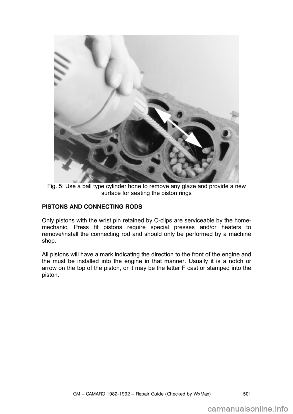
REFINISHING
Almost all engine block refinishing must be performed by a machine shop. If the
cylinders are not to be rebored, then t he cylinder glaze can be removed with a
ball hone. When removing cylinder glaz e with a ball hone, use a light or
penetrating type oil to lubricate the hone. Do not allow the hone to run dry as
this may cause excessive scoring of t he cylinder bores and wear on the hone. If
new pistons are required, t hey will need to be installed to the connecting rods.
This should be performed by a machine shop as the pistons must be installed in
the correct relationship to the rod or engine damage can occur.
Page 501 of 875

GM – CAMARO 1982-1992 – Repair Guide (Checked by WxMax) 501
Fig. 5: Use a ball type cylinder hone to remove any glaze and provide a new
surface for seating the piston rings
PISTONS AND CONNECTING RODS
Only pistons with the wrist pin retained by C-clips are serviceable by the home-
mechanic. Press fit pistons require special presses and/or heaters to
remove/install the connecting rod and sh ould only be performed by a machine
shop.
All pistons will have a mark indicating the direction to the front of the engine and
the must be installed into the engine in that manner. Usually it is a notch or
arrow on the top of the piston, or it ma y be the letter F cast or stamped into the
piston.
Page 537 of 875

GM – CAMARO 1982-1992 – Repair Guide (Checked by WxMax) 537
ENGINE CONTROLS
EMISSION CONTROLS
CRANKCASE VENTILATION SYSTEM
OPERATION
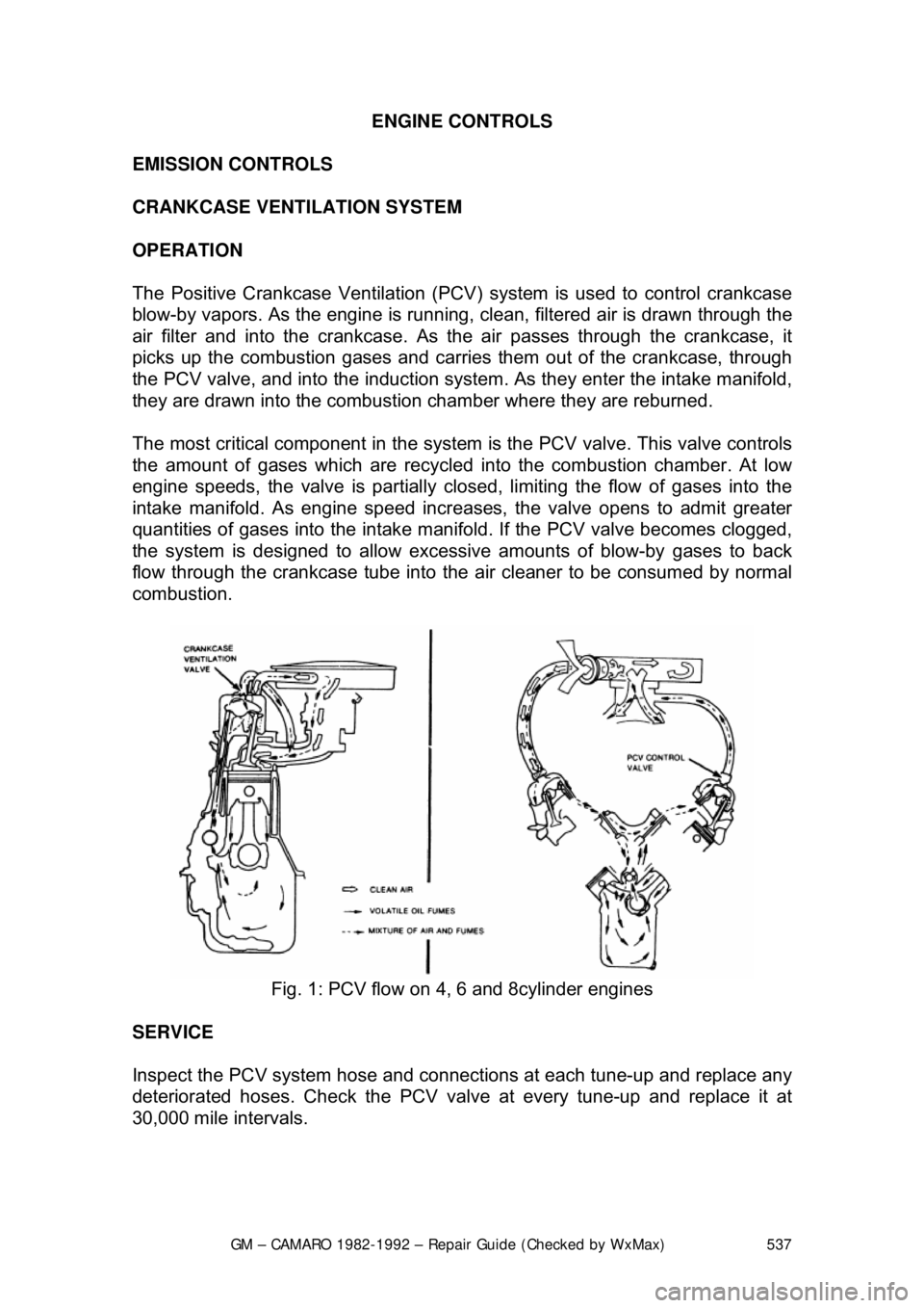
The Positive Crankcase Ventilation (PCV ) system is used to control crankcase
blow-by vapors. As the engine is running, clean, filtered air is drawn through the
air filter and into the crankcase. As the air passes through the crankca\
se, it
picks up the combustion gases and carries them out of the crankcase, through
the PCV valve, and into the induction system . As they enter the intake manifold,
they are drawn into the combustion chamber where they are reburned.
The most critical component in the system is the PCV valve. This valve controls
the amount of gases which are recycled into the combustion chamber. At low
engine speeds, the valve is partially clos ed, limiting the flow of gases into the
intake manifold. As engine speed incr eases, the valve opens to admit greater
quantities of gases into the intake manifold. If the PCV valve becomes clogged,
the system is designed to allow excessive amounts of blow-by gases to back
flow through the crankcase tube into the air cleaner to be consumed by normal
combustion.
Fig. 1: PCV flow on 4, 6 and 8cylinder engines
SERVICE
Inspect the PCV system hose and connecti ons at each tune-up and replace any
deteriorated hoses. Check the PCV valve at every tune-up and replace it at
30,000 mile intervals.
Page 551 of 875

GM – CAMARO 1982-1992 – Repair Guide (Checked by WxMax) 551
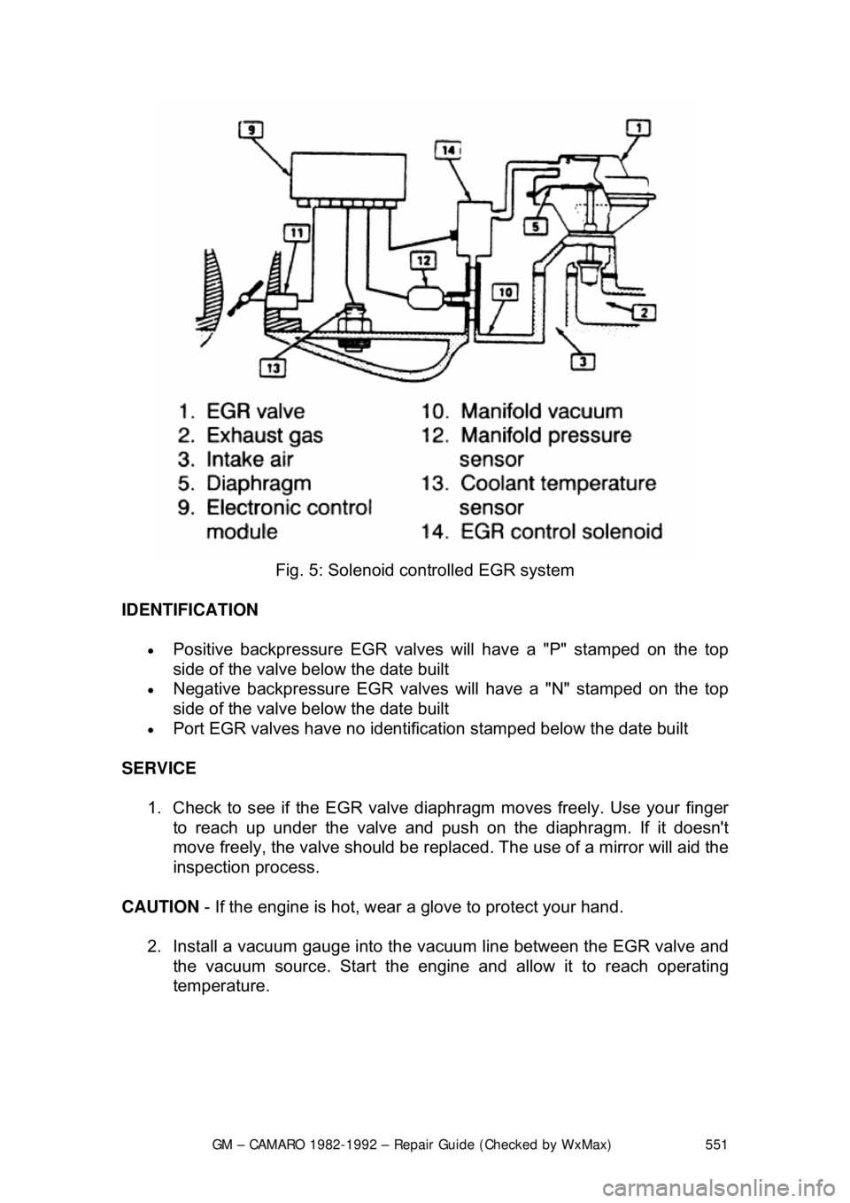
Fig. 5: Solenoid c ontrolled EGR system
IDENTIFICATION
• Positive backpressure EGR valves will have a "P" stamped on the top
side of the valve bel ow the date built
• Negative backpressure EGR valves will have a "N" stamped on the top
side of the valve bel ow the date built
• Port EGR valves have no identificat ion stamped below the date built
SERVICE 1. Check to see if the EGR valve di aphragm moves freely. Use your finger
to reach up under the valve and pus h on the diaphragm. If it doesn't
move freely, the valve should be repl aced. The use of a mirror will aid the
inspection process.
CAUTION - If the engine is hot, wear a glove to protect your hand.
2. Install a vacuum gauge into the vacuum line between the EGR valve and
the vacuum source. Star t the engine and allow it to reach operating
temperature.
Page 560 of 875

GM – CAMARO 1982-1992 – Repair Guide (Checked by WxMax) 560
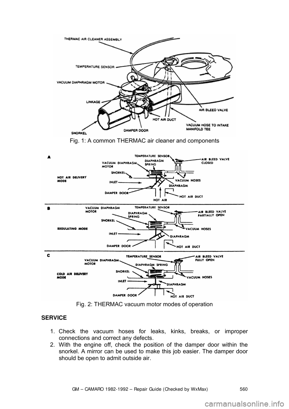
Fig. 1: A common THERMAC air cleaner and components
Fig. 2: THERMAC vacuum motor modes of operation
SERVICE 1. Check the vacuum hoses for leaks, kinks, breaks, or improper connections and correct any defects.
2. With the engine off, check the pos ition of the damper door within the
snorkel. A mirror can be used to make this job easier. The damper door
should be open to admit outside air.
Page 573 of 875

GM – CAMARO 1982-1992 – Repair Guide (Checked by WxMax) 573
7. Install the retaining bracket.
8. Connect the negative battery cable.
ELECTRONIC ENGINE CONTROLS
COMPUTER COMMAND CO NTROL (CCC) SYSTEM
The Computer Command Control (CCC) Sy stem is an electronically controlled
exhaust emission system that can m onitor and control a large number of
interrelated emission cont rol systems. It can monitor various engine/vehicle
operating conditions and then use this in formation to control multiple engine
related systems. The CCC syst em is thereby making constant adjustments to
maintain optimum vehicle performance und er all normal driving conditions while
at the same time allowing the catalyti c converter to effectively control the
emissions of HC, CO and NO
x.
OPERATION
The Electronic Control Module (ECM) is required to maintain the exhaust
emissions at acceptable le vels. The module is a sma ll, solid state computer
which receives signals from many source s and sensors; it uses these data to
make judgements about operating conditions and then control output signals to
the fuel and emission systems to ma tch the current requirements.
Inputs are received from m any sources to form a complete picture of engine
operating conditions. Some inputs are simp ly Yes or No messages, such as that
from the Park/Neutral switch; the vehicle is either in gear or in Park/Neutral;
there are no other choices. Other data is sent in quantitative input, such as
engine rpm or coolant temperature. T he ECM is pre-programmed to recognize
acceptable ranges or combinations of si gnals and control the outputs to control
emissions while providing good driv eability and economy. The ECM also
monitors some output circuits, making sure that the components function as
commanded. For proper engine oper ation, it is essential that all input and output
components function properly and comm unicate properly with the ECM.
Since the control module is programmed to recognize the presence and value
of electrical inputs, it will also note the lack of a signal or a radical change in
values. It will, for example, react to the loss of signal from the vehicle speed
sensor or note that engine coolant temperature has risen beyond acceptable
(programmed) limits. Once a fault is recognized, a numeric code is assigned
and held in memory. The SERVICE ENGIN E SOON Malfunction Indicator Lamp
(MIL), will illuminate to advise the operator that the system has detected a fault.
More than one code may be stored. Although not every engine uses every
code, possible codes range from 12-999. Additionally, the same code may carry
different meanings relative to each engine or engine family. For example, on the
3.3L (VIN N) engine, code 46 indicates a fault found in the power steering
pressure switch circuit. The same code on the 5.7L (VIN F) engine indicates a
fault in the VATS anti-theft system.