CHEVROLET CAMARO 1982 Repair Guide
Manufacturer: CHEVROLET, Model Year: 1982, Model line: CAMARO, Model: CHEVROLET CAMARO 1982Pages: 875, PDF Size: 88.64 MB
Page 561 of 875

GM – CAMARO 1982-1992 – Repair Guide (Checked by WxMax) 561
3. Apply at least 7 in. Hg of vacuum
to the damper diaphragm unit. The
door should close. If it doesn't, che ck the diaphragm linkage for binding
and correct hookup.
4. With the vacuum still applied and t he door closed, clamp the tube to trap
the vacuum. If the door doesn't remain closed, there is a leak in the
diaphragm assembly.
REMOVAL & INSTALLATION
VACUUM MOTOR 1. Remove the air cleaner.
2. Disconnect the vacuum hose from the motor.
3. Drill out the spot welds with a
1/8 inch (3mm) bit, then enlarge as
necessary to remove the retaining strap.
4. Remove the retaining strap.
5. Lift up the motor and cock it to o ne side to unhook the motor linkage at
the control damper assembly.
To install: 6. In order to install t he new vacuum motor, drill a
7/64 inch (2.8mm) hole in
the snorkel tube as the c enter of the vacuum motor retaining strap.
7. Insert the vacuum motor linkage into the control damper assembly.
8. Use the motor retaining strap and a sheet metal screw to secure the
retaining strap and motor to the snorkel tube.
Make sure the screw does not interf ere with the operation of the damper
assembly. Shorten the screw if necessary.
TEMPERATURE SENSOR 1. Remove the air cleaner.
2. Disconnect the hoses at the air cleaner.
3. Pry up the tabs on the sensor reta ining clip and remove the clip and
sensor from the air cleaner.
To install: 4. Position sensor into air cleaner.
5. Install retaining clip.
6. Connect the hoses to the air cleaner.
7. Install the air cleaner.
AIR INJECTION REACTION (AIR) SYSTEM
OPERATION
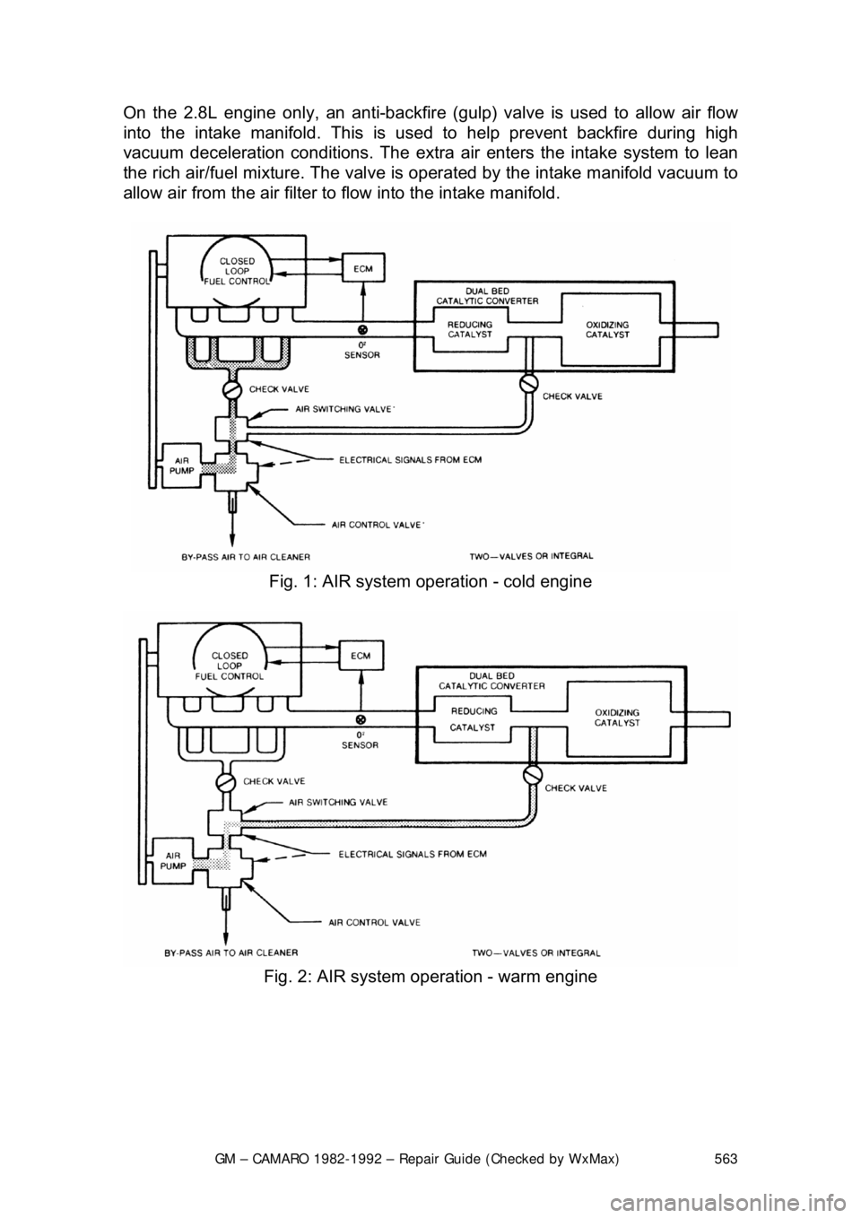
The AIR management system is used to prov ide additional oxygen to continue
the combustion process after the exhaus t gases leave the combustion chamber.
Page 562 of 875

GM – CAMARO 1982-1992 – Repair Guide (Checked by WxMax) 562
Air is injected into either the exhaust
port(s), the exhaust manifold(s) or the
catalytic converter by an engine driven ai r pump. The system is in operation at
all times and will bypass air only mom entarily during deceleration and at high
speeds. The bypass function is performed by the air control valve, while the
check valve protects the air pump by pr eventing any backflow of exhaust gases.
The AIR system helps r educe HC and CO content in the exhaust gases by
injecting air into the exhaust ports dur ing cold engine operation. This air
injection also helps the catalytic conv erter to reach the proper temperature
quicker during warmup. When the engine is warm (Closed Loop), the AIR
system injects air into the beds of a th ree-way converter to lower the HC and
the CO content in the exhaust.
The system utilizes the following components:
1. An engine driven AIR pump.
2. AIR Control valves (Air Control, Air Switching).
3. Air flow and control hoses.
4. Check valves.
5. A dual-bed, three-way catalytic converter.
6. A deceleration back-fire control valve - 2.8L engine only.
The belt driven, vane-type air pump is lo cated at the front of the engine and
supplies clean air to the AIR system fo r purposes already stated. When the
engine is cold, the Electronic Control Module (ECM) energizes an AIR control
solenoid. This allows air to flow to the AIR switching valve. The AIR switching
valve is then energized to direct air to the exhaust ports.
When the engine is warm, the ECM de-energ izes the AIR switching valve, thus
directing the air between the beds of the catalytic converter. This provides
additional oxygen for the ox idizing catalyst in the second bed to decrease HC
and CO, while at the same time keeping oxygen levels low in the first bed,
enabling the reducing catalyst to effect ively decrease the levels of NOx.
If the AIR control valve detects a r apid increase in manifold vacuum
(deceleration), certain operat ing modes (wide open throttle, etc.) or if the ECM
self-diagnostic system detects any problem in the system, air is diverted to the
air cleaner or directly into the atmosphere.
The primary purpose of the EC M's divert mode is to prevent backfiring. Throttle
closure at the beginning of deceleration will temporarily create air/fuel mixtures
which are too rich to burn completely . These mixtures become burnable when
they reach the exhaust if combined with the injection ai r. The next firing of the
engine will ignite this mixt ure causing an exhaust backf ire. Momentary diverting
of the injection air from the exhaust prevents this.
The AIR system check valves and hoses should be checked periodically for any
leaks, cracks or deterioration.
Page 563 of 875
GM – CAMARO 1982-1992 – Repair Guide (Checked by WxMax) 563
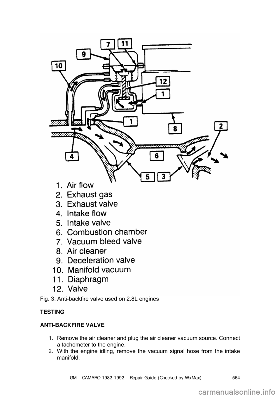
On the 2.8L engine only, an anti-backfire (g
ulp) valve is used to allow air flow
into the intake manifold. This is us ed to help prevent backfire during high
vacuum deceleration conditions. The extra air enters the intake system to lean
the rich air/fuel mixture. The valve is o perated by the intake manifold vacuum to
allow air from the air filter to flow into the intake manifold.
Fig. 1: AIR system operation - cold engine
Fig. 2: AIR system operation - warm engine
Page 564 of 875
GM – CAMARO 1982-1992 – Repair Guide (Checked by WxMax) 564
Fig. 3: Anti-backfire valve used on 2.8L engines
TESTING
ANTI-BACKFIRE VALVE
1. Remove the air cleaner and plug t he air cleaner vacuum source. Connect
a tachometer to the engine.
2. With the engine idling, remove the vacuum signal hose from the intake
manifold.
Page 565 of 875

GM – CAMARO 1982-1992 – Repair Guide (Checked by WxMax) 565
3. Reconnect the signal
hose and listen for air flow through the ventilation
tube into the anti-backfire valve. A speed drop should be noticed when
the hose is reconnected.
4. If these conditions are not found, check hoses for restrictions or leaks. If
hoses are OK, replace the anti-backfire valve.
AIR PUMP 1. Check the drive belt tension.
2. Increase the engine speed and observe an increase in air flow. If air flow
does not increase, replace the air pump.
CONTROL VALVE 1. Remove the hoses. Blow through t he valve (toward the cylinder head).
2. Then, suck through the valve (or blow through the other side). If air flows
in one direction, the valve is operative. If not, replace the control valve.
REMOVAL & INSTALLATION
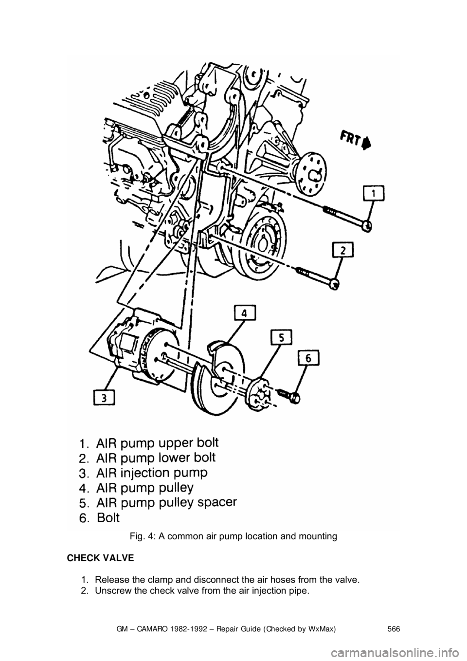
AIR PUMP 1. Remove the AIR control valves and/or adapter at the pump.
2. Loosen the air pump adjustment bolt and remove the drive belt.
3. Unscrew the pump mounting bolts and then remove the pump pulley.
4. Unscrew the pump mounting bol ts and then remove the pump.
To install: 5. Position the pump into place and secure it with the mounting bolts.
6. Install the pump pulley.
7. Install the air pump drive belt and adjust pump belt with the pump
adjustment bolt.
8. Install the AIR contro l valves and/or adapter.
Page 566 of 875
GM – CAMARO 1982-1992 – Repair Guide (Checked by WxMax) 566
Fig. 4: A common air pump location and mounting
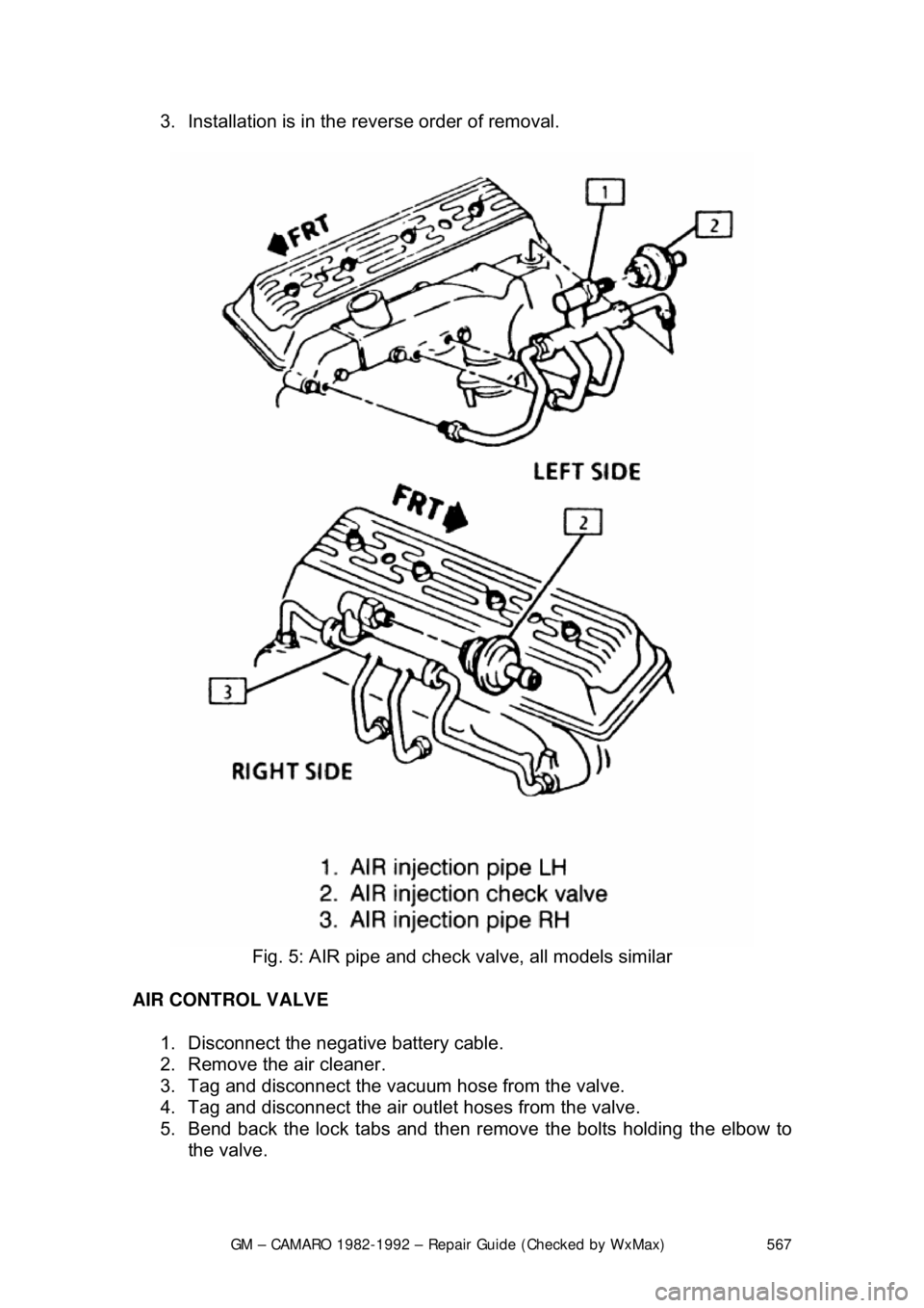
CHECK VALVE 1. Release the clamp and disconnect the air hoses from the valve.
2. Unscrew the check valve from the air injection pipe.
Page 567 of 875
GM – CAMARO 1982-1992 – Repair Guide (Checked by WxMax) 567
3. Installation is in the reverse order of removal.
Fig. 5: AIR pipe and check valve, all models similar
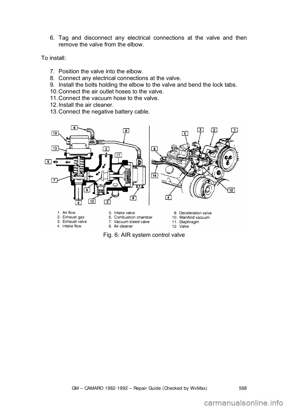
AIR CONTROL VALVE 1. Disconnect the negative battery cable.
2. Remove the air cleaner.
3. Tag and disconnect the vacuum hose from the valve.
4. Tag and disconnect the air outle t hoses from the valve.
5. Bend back the lock tabs and then remo ve the bolts holding the elbow to
the valve.
Page 568 of 875
GM – CAMARO 1982-1992 – Repair Guide (Checked by WxMax) 568
6. Tag and disconnect any electrical
connections at the valve and then
remove the valve from the elbow.
To install: 7. Position the valve into the elbow.
8. Connect any electrical c onnections at the valve.
9. Install the bolts holding the elbow to the valve and bend the lock tabs.
10. Connect the air outlet hoses to the valve.
11. Connect the vacuum hose to the valve.
12. Install the air cleaner.
13. Connect the negative battery cable.
Fig. 6: AIR system control valve
Page 569 of 875
GM – CAMARO 1982-1992 – Repair Guide (Checked by WxMax) 569
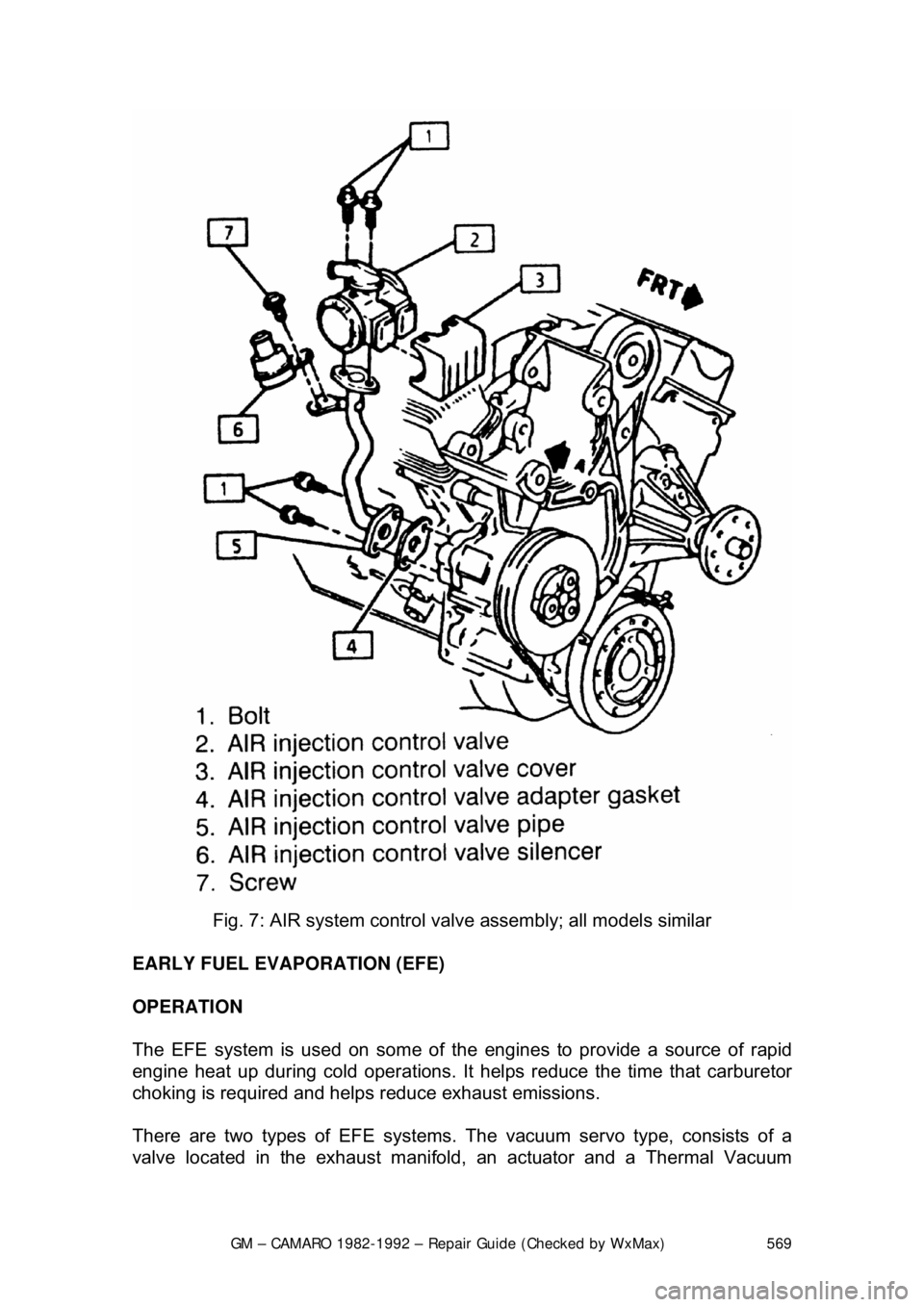
Fig. 7: AIR system control valv e assembly; all models similar
EARLY FUEL EVAPORATION (EFE)
OPERATION
The EFE system is used on some of the engines to provide a source of rapid
engine heat up during cold operations. It hel ps reduce the time that carburetor
choking is required and helps reduce exhaust emissions.
There are two types of EF E systems. The vacuum servo type, consists of a
valve located in the exhaust manifold , an actuator and a Thermal Vacuum
Page 570 of 875

GM – CAMARO 1982-1992 – Repair Guide (Checked by WxMax) 570
Switch (TVS). The electrical type, cons
ists of a ceramic grid located under the
base of the carburetor.
A check of the operation should be made at regular maintenance intervals.
TESTING
VACUUM SERVO TYPE 1. With the engine cold, observe the posit ion of the actuator arm. Start the
engine. The arm should move toward the diaphragm (closing the valve).
2. If the arm does not move, remove the hose and check for vacuum. If still
no vacuum, remove the top hose from the TVS switch and check for
vacuum.
3. If vacuum is present in the top hose, replace the TVS switch.
4. If vacuum is present at the actuator and it does not move, try to free the
valve. If the valve cannot be freed, it must be replaced.
ELECTRICAL TYPE 1. Turn the ignition ON with the engine co ld and probe both terminals of the
heater switch connector with a test light.
• If 1 wire has power, replace the heater switch.
• If neither wire has power, repai r the ignition circuit.
• If both wires have power, probe the pink wire at the heater
connector (if no power, repair the c onnector of the heater switch).
2. If power exists at the pink wire , disconnect the heater connector and
connect a tester across the harness terminal. If no power, repair the
ground wire; if power exists, check the resistance of the heater.
3. If heater is over 3 ohm s, replace the heater. If under 3 ohms, replace the
connector, start the engine (operate to normal temperature) and probe
the pink wire. If no power, the system is OK; if power exists, replace the
heater switch.
REMOVAL & INSTALLATION
VACUUM SERVO TYPE 1. Disconnect the vacuum hose at the EFE.
2. Remove exhaust pipe to manifold nuts.
3. Remove the crossover pipe. Complete removal is not always necessary.
4. Remove the EFE valve.
To install: 5. Position the EFE valve into place.
6. Install the crossover pipe.
7. Install the exhaust pi pe to manifold nuts.
8. Connect the vacuum hose at the EFE.