head CHEVROLET CAMARO 1982 Repair Guide
[x] Cancel search | Manufacturer: CHEVROLET, Model Year: 1982, Model line: CAMARO, Model: CHEVROLET CAMARO 1982Pages: 875, PDF Size: 88.64 MB
Page 4 of 875
GM – CAMARO 1982-1992 – Repair Guide (Checked by WxMax) 4
1. On doors that are equipped with
power operated components, do the
following:
• Remove the door trim panel an d inner panel water deflector.
• Disconnect the wire harness from all components in the door.
• Remove the rubber conduit from t he door, then remove the wire harness
from the door through t he conduit access hole.
2. Tape the area (on the door pillar and b ody pillar) above the lower hinge with
cloth backed body tape.
CAUTION - Before performing the following step, cover the spring with a shop
cloth or rag to prevent the spring fr om flying and possibly causing personal
injury or damage.
3. Insert a long, flat-blade screwdriver under the pivot point of the hold-open
link and over the top of the spring. T he screwdriver should be positioned so
as not to apply pressure to the hol d-open link. Cover the spring with a shop
cloth or rag and lift the screwdriver to disengage the spring. The spring can
also be removed by using tool J- 36604 (or equivalent) door hinge spring
compressor tool.
The tool is stamped right side and left side. The tool stamped left side is used to
service the right-hand hinge spring and vi se-a-versa for the tool stamped right
side.
4. With the aid of a helper to suppor t the door, remove the lower hinge pin
using a soft-headed hammer and locking type pliers. The helper can aid the
hinge pin removal by raising and lowering the rear of the door.
5. Insert a bolt into the hole of the lo wer hinge to maintain the door attachment
during upper hinge removal.
6. Using a 13mm socket, remove the upper hinge bolts from the pillar. Remove
the bolt from the lower hinge and re move the door from the body.
To install:
7. Replace the hinge pin clip.
8. With the aid of a helper, position t he door and insert the bolt in the hole of
the lower hinge.
9. Bolt the upper hinge to the body. The lower hinge pin is installed with the
pointed end down.
10. Remove the screw from the lower hi nge and install the lower hinge pin. The
use of tool J-36604 or equi valent is recommended for installing the hinge
spring.
If the spring is installed before inst alling the lower hinge pin, damage to the
hinge bushings may result.
11. If the spring was removed using a screw driver, install the spring as follows:
Page 11 of 875
GM – CAMARO 1982-1992 – Repair Guide (Checked by WxMax) 11
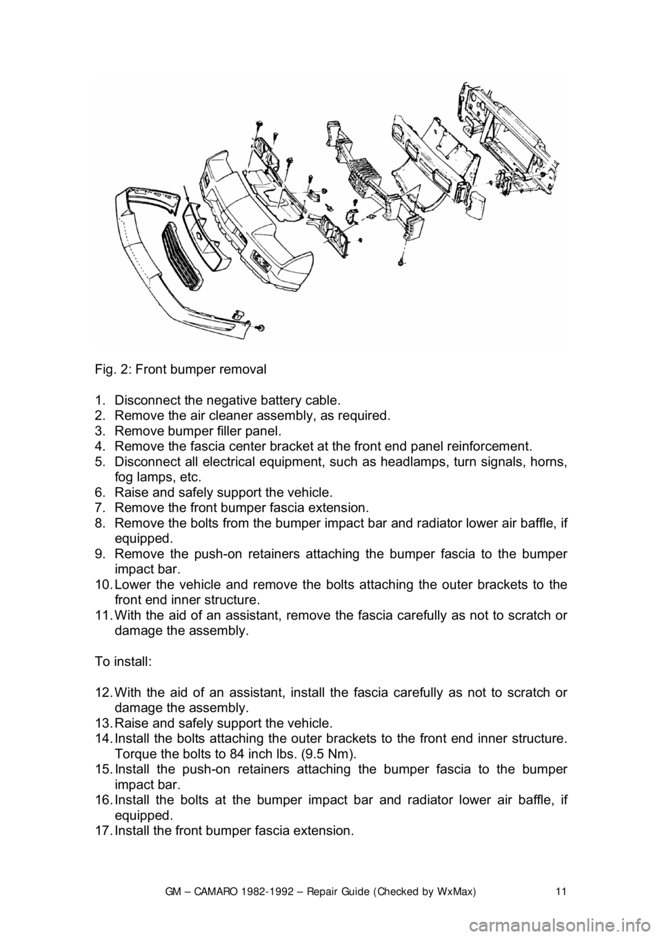
Fig. 2: Front bumper removal
1. Disconnect the negative battery cable.
2. Remove the air cleaner assembly, as required.
3. Remove bumper filler panel.
4. Remove the fascia center bracket at the front end panel reinforcement.
5. Disconnect all electrical equipment, su ch as headlamps, turn signals, horns,
fog lamps, etc.
6. Raise and safely support the vehicle.
7. Remove the front bumper fascia extension.
8. Remove the bolts from the bumper impac t bar and radiator lower air baffle, if
equipped.
9. Remove the push-on retainers attach ing the bumper fascia to the bumper
impact bar.
10. Lower the vehicle and remove the bolt s attaching the outer brackets to the
front end inner structure.
11. With the aid of an assistant, remove t he fascia carefully as not to scratch or
damage the assembly.
To install:
12. With the aid of an assistant, install t he fascia carefully as not to scratch or
damage the assembly.
13. Raise and safely support the vehicle.
14. Install the bolts attachi ng the outer brackets to the front end inner structure.
Torque the bolts to 84 inch lbs. (9.5 Nm).
15. Install the push-on retainers atta ching the bumper fascia to the bumper
impact bar.
16. Install the bolts at t he bumper impact bar and radiat or lower air baffle, if
equipped.
17. Install the front bum per fascia extension.
Page 12 of 875
GM – CAMARO 1982-1992 – Repair Guide (Checked by WxMax) 12
18. Connect all electrical equipment, such
as headlamps, turn signals, horns,
fog lamps, etc.
19. Install the fascia center bracket at the front end panel reinforcement.
20. Install bumper filler panel.
21. Install the air cleaner assembly, as required.
22. Connect the negative battery cable.
REAR
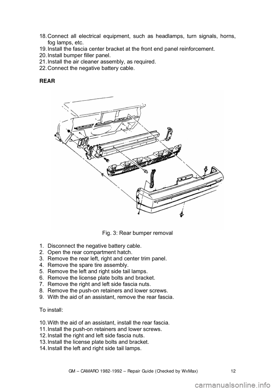
Fig. 3: Rear bumper removal
1. Disconnect the negative battery cable.
2. Open the rear compartment hatch.
3. Remove the rear left, ri ght and center trim panel.
4. Remove the spare tire assembly.
5. Remove the left and right side tail lamps.
6. Remove the license plate bolts and bracket.
7. Remove the right and left side fascia nuts.
8. Remove the push-on retainers and lower screws.
9. With the aid of an assistan t, remove the rear fascia.
To install:
10. With the aid of an assistan t, install the rear fascia.
11. Install the push-on retainers and lower screws.
12. Install the right and left side fascia nuts.
13. Install the license plate bolts and bracket.
14. Install the left and right side tail lamps.
Page 23 of 875
GM – CAMARO 1982-1992 – Repair Guide (Checked by WxMax) 23
4. Remove the No. 1 bow garni
sh molding and retainer.
5. Remove the top from the No. 1 bow by applying heat with a heat gun to the
approximately 1 in. (25mm) fr om the adhesive backed bow.
6. Remove the cable screws.
7. Remove the headliner from the No. 2 and 3 bows.
It is not necessary to remove the headliner from the No. 1 bow with the top
folded enough to allow access to the retainer screws.
8. Remove the screws from the under side of the Nos. 2 and 3 top cover
retainers.
9. Remove the No. 2 and 3 bow top cover from the pockets in the top cover.
10. Separate the outer quarter flaps fr om the main pillar post, once again using
the heat gun as necessary to loosen the adhesive.
11. Remove the side retention cables.
12. Remove screws.
13. Remove the elastic stays, folding the top rearward.
14. Remove the No. 5 bow seal.
15. Remove the black covered rive ts from the No. 5 bow using an
1/8 in. (3mm)
drill bit.
16. Remove the top cover from No. 5 bow, using heat as required to loosen th\
e adhesive.
17. Remove the convertible t op cover from the vehicle.
To install:
Use 3M® adhesive No. 8046 or equivalent on cover attaching surfaces where
noted.
18. Install the cover on the v ehicle. Slide the retention cables through the listing
pockets and check cable ends for proper locations.
19. Square the top to the frame; check fo r evenness of quarter flap positions to
the main pillar rail. Fold the t op cover to the windshield header.
20. Apply adhesive to the No . 5 bow and top, raise the No. 5 bow to the full
vertical position.
Glue
1/2 of the top cover to the No. 5 bow first, then lower the bow and check for
evenness. The length of the material ov erhanging should be uniform. Repeat
the procedure, if necessary. Trim the exce ss fabric from the No. 5 bow evenly at
the seal channel to allow atta chment of the seal later.
21. Install new
1/8 in. (3mm) by 3/16 in. (5mm) black aluminum rivets as shown in
illustration.
22. Lower and latch the tonneau cover and No. 5 bow. Raise the No. 1 bow off
the header and install the cable screws.
23. Install the No. 5 bow seal.
24. Connect the elastic stays inside of No . 5 bow seal-to-link arms. Install the
screws.
25. Lower the No. 5 bow. Fold the inner quarter flaps inside of main pillar rails.
Fold the outer quarter flaps around the outs ide of the main pillar rails to the
Page 24 of 875
GM – CAMARO 1982-1992 – Repair Guide (Checked by WxMax) 24
forward edge using adhesive on the flaps and rails. Ensure seams are
aligned evenly on both rails. Trim excess material.
26. Raise No. 5 bow. Raise the tonneau panel and lower No. 5 bow. Slide the
No. 2 and 3 bow top cover retainers into listing pockets and align screw
holes. Install the screws to the underside of No. 2 and 3 bows.
27. Install the headliner to No. 2 and 3 bows.
28. Latch the top to the wi ndshield header and pull the to p cover straight forward
at the seams over the No. 1 bow to desired fullness. While maintaining
tension on the top cover over the No. 1 bow, make a pencil mark on the
outer surface along the forwar d edge of the No. 1 bow.
29. Unlatch the top from the windshield header and lowe r the top halfway. Pull
the top cover
1/4 in. (6mm) past the reference mark over the No. 1 bow and
attach it to the No. 1 bow, first attach ing cover side flaps. Fold the side flaps
around the bow using adhesive on both the cover and bow surfaces. Fold
the top cover over the No. 1 bow al ong the edge and over the cover side
flap, once again using adhesive. Lower t he top and check for proper tension,
if more is needed, repeat the procedur e. Trim off excess material.
30. Install all moldings, pillar seals, side seals and retainers. Replace dried out,
deteriorated or cracked seals to prevent air and water leaks.
31. Adjust the top upstops and downstops, as required.
ADJUSTMENT
UPSTOP
The upstops may be adjusted to obtain pr oper alignment between the top latch
guide pins and the windshield header receivers.
1. Lower the top. Loosen the upstop ja m nut and turn screw clockwise.
2. Raise and latch the top.
3. Raise No. 5 bow to the full vertical position.
4. Turn the upstops counterclockwis e until they contact the linkage.
5. Unlatch and lower the top. Tight en the upstop jam nut while holding the
upstop from turning.
6. Raise the top and inspect the alignment of the top latch guide pins to the
header receivers.
DOWNSTOP
The downstops can be adjusted for proper clearance between the main rail and
No. 4 bow when the top is lowered comple tely. The downstops have right angle
bends and face outward.
1. Raise and latch the top.
2. Loosen the downstops nuts and adjust as required.
3. Tighten the downstop nuts while holding downstops in position.
4. Lower the top and inspec t the clearance between the main rail and the No. 4
bow. Also inspect the clear ance of the tonneau panel.
Page 29 of 875
GM – CAMARO 1982-1992 – Repair Guide (Checked by WxMax) 29
attachment hole in the trim panel, rotate the retainer until the flange is
engaged fully.
12. Connect all electrical components where present.
13. To install the door trim panel, locate the top of the assembly over the upper
flange of the door inner panel, inserting the door handle through the handle
slot in the panel and press down on the trim panel to engage the upper
retaining clips.
14. Position the trim panel to the door inner panel so the trim retainers are
aligned with the attaching holes in t he panel and tap the retainers into the
holes with the palm of hand or a clean rubber mallet.
15. Install the screws used to hold the armrest to the inner panel.
16. Install the remote control handle bezel screws.
17. On models with power door lock contro ls located in the door trim panel,
connect the wire harnesses at the switch assemblies.
18. On models with remote control mirror assemblies, install the control to the
plate. Install the control plate to the bezel on the trim pad.
19. Install the handle assemb ly and install the screws inserted through the door
armrest.
20. Install the door inside locking rod knob.
21. Install all the door inside handles.
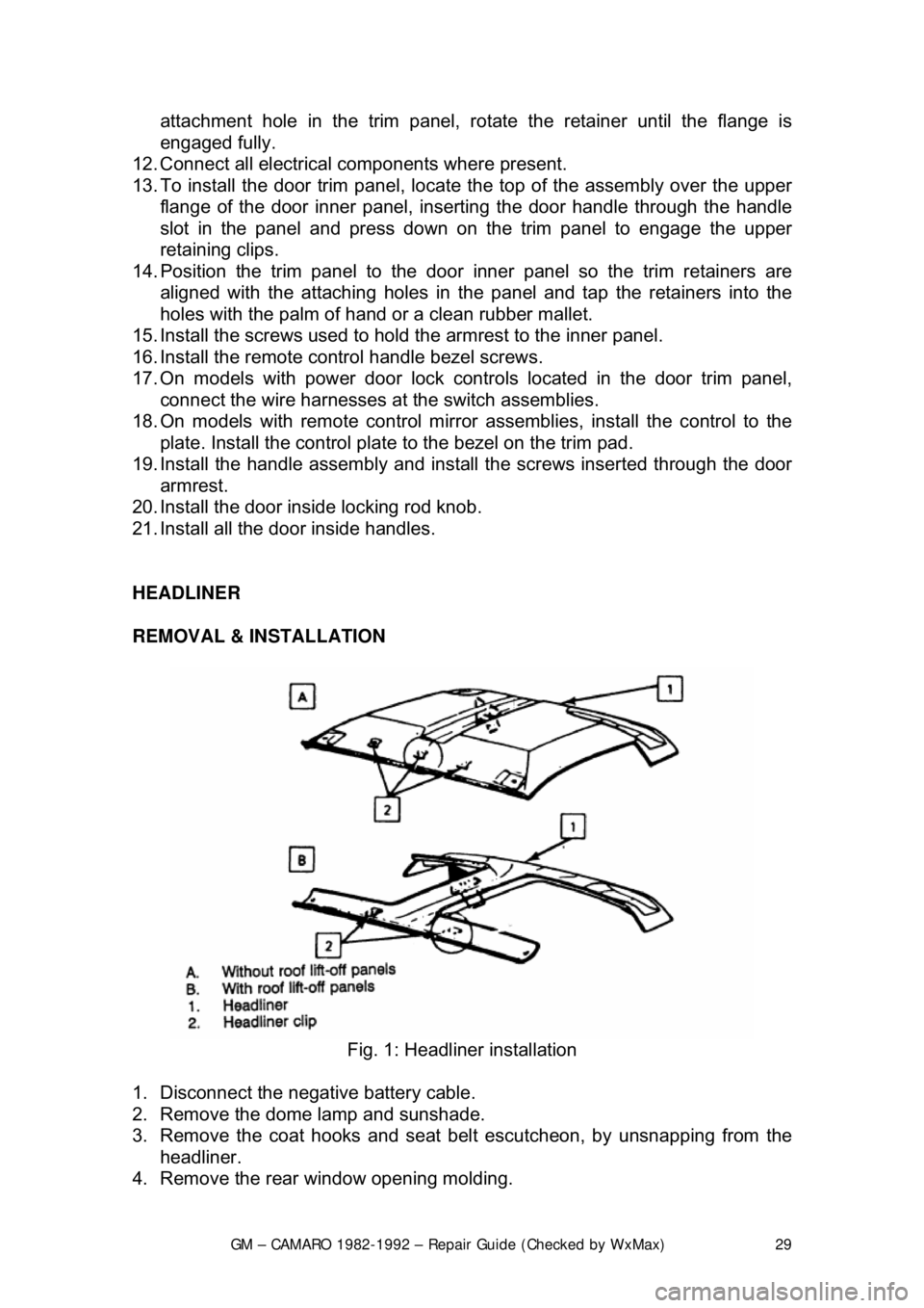
HEADLINER
REMOVAL & INSTALLATION
Fig. 1: Headliner installation
1. Disconnect the negative battery cable.
2. Remove the dome lamp and sunshade.
3. Remove the coat hooks and seat bel t escutcheon, by unsnapping from the
headliner.
4. Remove the rear window opening molding.
Page 30 of 875
GM – CAMARO 1982-1992 – Repair Guide (Checked by WxMax) 30
5. Remove the rear quarter interior
trim panels, body lock pillar panels and
windshield side upper moldings.
6. Remove the headliner retaining clips and remove the headliner.
7. Installation is the revers e of the removal procedure.
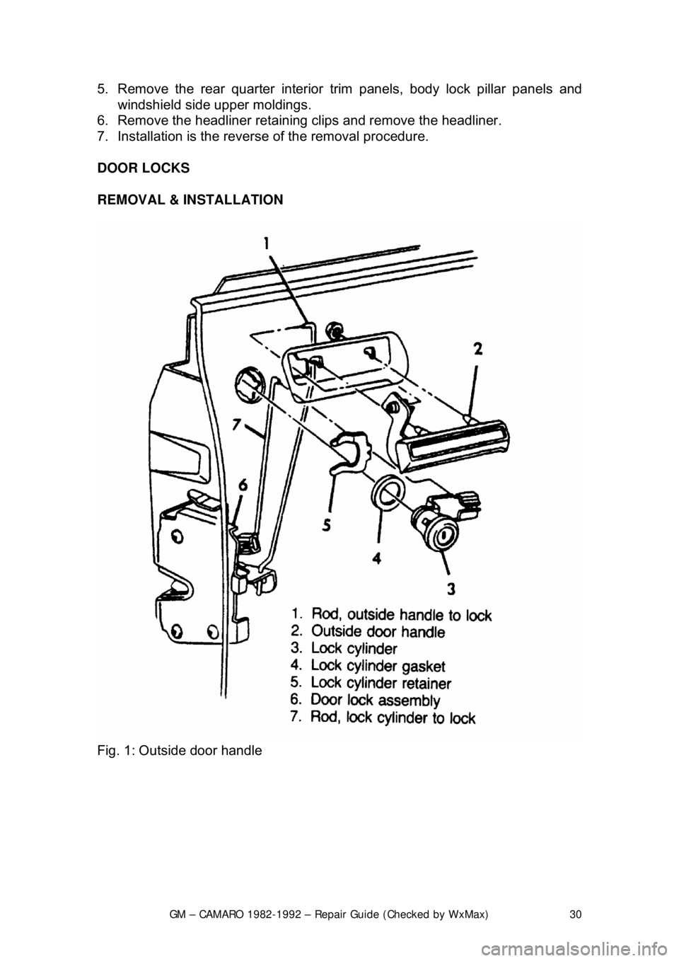
DOOR LOCKS
REMOVAL & INSTALLATION
Fig. 1: Outside door handle
Page 33 of 875
GM – CAMARO 1982-1992 – Repair Guide (Checked by WxMax) 33
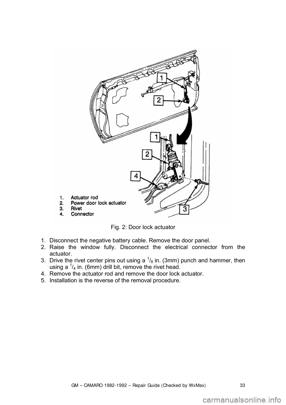
Fig. 2: Door lock actuator
1. Disconnect the negative battery c able. Remove the door panel.
2. Raise the window fully. Disconnect t he electrical connector from the
actuator.
3. Drive the rivet cent er pins out using a
1/8 in. (3mm) punch and hammer, then
using a 1/4 in. (6mm) drill bit, remove the rivet head.
4. Remove the actuator rod and remove the door lock actuator.
5. Installation is the revers e of the removal procedure.
Page 79 of 875
GM – CAMARO 1982-1992 – Repair Guide (Checked by WxMax) 79
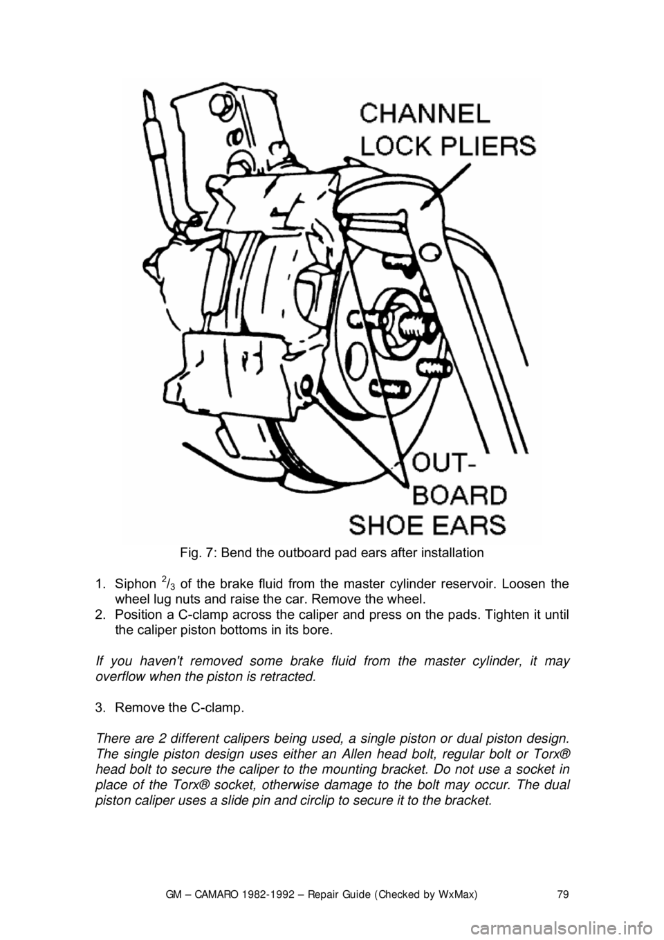
Fig. 7: Bend the outboard pad ears after installation
1. Siphon
2/3 of the brake fluid from the ma ster cylinder reservoir. Loosen the
wheel lug nuts and raise the car. Remove the wheel.
2. Position a C-clamp across the caliper and press on the pads. Tighten it until
the caliper piston bottoms in its bore.
If you haven't removed some brake fluid from the master cylinder, it may
overflow when the piston is retracted.
3. Remove the C-clamp.
There are 2 different calip ers being used, a single pist on or dual piston design.
The single piston design uses either an Allen head bolt, regular bolt or Torx®
head bolt to secure the caliper to the mounting bracket. Do not use a socket in
place of the Torx® socket, otherwise damage to the bolt may occur. The dual
piston caliper uses a slide pin and ci rclip to secure it to the bracket.
Page 82 of 875
GM – CAMARO 1982-1992 – Repair Guide (Checked by WxMax) 82
Avoid inhaling any dust from
any brake surface! When cleaning brake surfaces,
use a commercially available brake cleaning fluid.
1. Remove
2/3 of the brake fluid from the mast er cylinder. Raise the vehicle and
remove the wheel.
2. Place a C-clamp across the caliper, positioned on the brake pads. Tighten it
until the piston is forced into its bore.
3. Remove the C-clamp. Remove the bolt holding the brake hose to the caliper.
4. Remove the Allen head caliper mounting bolts. Inspect them for corrosion
and replace them if necessary. Remove the caliper.
To install:
5. Position the caliper with the brake pad installed and install Allen head caliper
mounting bolts. Mounting bo lt torque is 21-35 ft. lbs. (28-47 Nm.) for the
caliper.
6. Install the bolt holding the brake hos e to the caliper and tighten to 18-30 ft.
lbs. (24-40 Nm.).
7. Fill the master cylinder with brake fluid.
8. Install the wheels and lower the vehicle.
CAUTION - Before moving the vehicle, pump the brakes several times to seat
the brake pad against the rotor
OVERHAUL
Some vehicles may be equipped dual piston calipers. The procedure to
overhaul the caliper is e ssentially the same with t he exception of multiple
pistons, O-rings and dust boots.
1. Remove the caliper from the ve hicle and place on a clean workbench.
CAUTION - NEVER place your finger s in front of the pistons in an attempt to
catch or protect the pistons when applying compressed air. This could result in
personal injury!
Depending upon the vehicle, there are two different ways to remove the piston
from the caliper. Refer to the brake pad replacement procedure to make sure
you have the correct procedure for your vehicle.
2. The first method is as follows: a. Stuff a shop towel or a block of wood into the caliper to catch the piston.
b. Remove the caliper piston using co mpressed air applied into the caliper
inlet hole. Inspect the piston for scor ing, nicks, corrosion and/or worn or
damaged chrome plating. The piston mu st be replaced if any of these
conditions are found.