ABS CHEVROLET CAMARO 1982 Repair Guide
[x] Cancel search | Manufacturer: CHEVROLET, Model Year: 1982, Model line: CAMARO, Model: CHEVROLET CAMARO 1982Pages: 875, PDF Size: 88.64 MB
Page 14 of 875

GM – CAMARO 1982-1992 – Repair Guide (Checked by WxMax) 14
2. Remove the mirror base-to-door outer
panel stud nuts, remove the cable
from the clip and remove the mirror and cable assembly from the door.
3. Position the mirror onto the door ma king sure the mirror gasket is properly
aligned on the door outer panel.
4. Install the cable onto the clip and install the mirror base-to-door outer panel
stud nuts. Torque to 72 inch lbs. (8 Nm).
5. Install the inner panel wate r deflector and door trim panel.
6. Install the mirror remote control bezel.
POWER OPERATED MIRRORS
Disconnect the negative battery terminal and, from the door trim panel side,
remove the remote control mirror bezel , release and remove the door panel.
1. Disconnect wire harness connection from t he remote mirror electrical switch.
2. Peel back water deflect or enough to detach the har ness from the retaining
tabs in the door.
3. Remove the mirror base-to-door stud nuts and lift mirror housing and
harness assembly from the door.
To install:
5. feed the mirror harness through the do or along with the mirror assembly.
Install the mirror base-to- door stud nuts and tighten.
6. Connect the mirror wire harness and install the water deflector.
7. Connect the wire harness connection to the remote mirror electrical switch.
8. Install the door panel and install the remote control mirror bezel.
9. Connect the negative battery terminal.
Page 74 of 875

GM – CAMARO 1982-1992 – Repair Guide (Checked by WxMax) 74
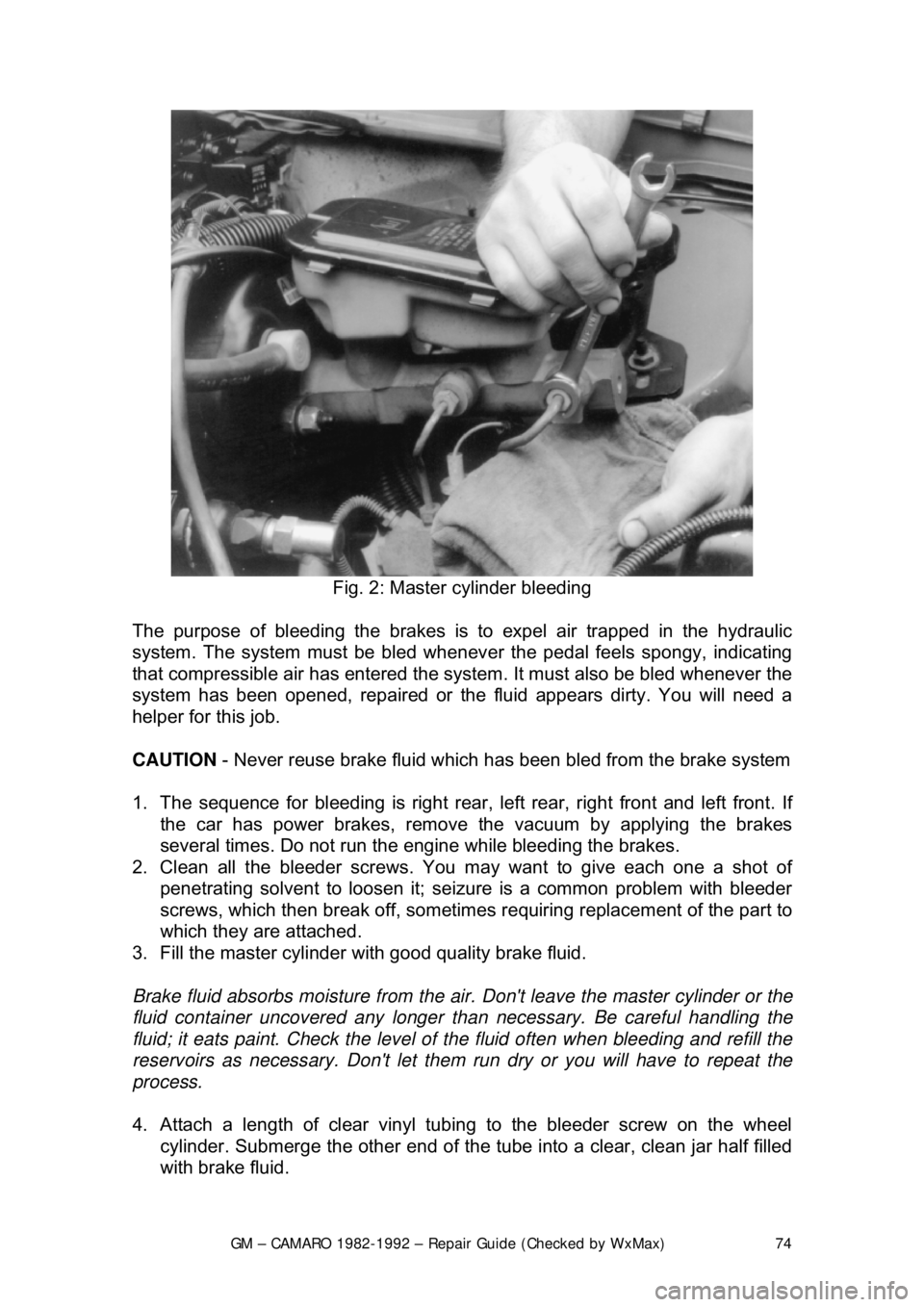
Fig. 2: Master cylinder bleeding
The purpose of bleeding the brakes is to expel air trapped in the hydraulic
system. The system must be bled whenever the pedal feels spongy, indicating
that compressible air has ent ered the system. It must also be bled whenever the
system has been opened, repaired or the fluid appears dirty. You will need a
helper for this job.
CAUTION - Never reuse brake fluid which has been bled from the brake system
1. The sequence for bleeding is right rear , left rear, right front and left front. If
the car has power brakes, remove the vacuum by applying the brakes
several times. Do not run the engine while bleeding the brakes.
2. Clean all the bleeder screws. You ma y want to give each one a shot of
penetrating solvent to loosen it; seiz ure is a common problem with bleeder
screws, which then break off, sometimes requiring replacement of the part to
which they are attached.
3. Fill the master cylinder with good quality brake fluid.
Brake fluid absorbs moisture from the air. Don't leave the master cylinder or the
fluid container uncovered any longer t han necessary. Be careful handling the
fluid; it eats paint. Check the level of the fluid often when bleeding and refill the
reservoirs as necessary. Don't let them run dry or you will have to repeat the
process.
4. Attach a length of clear vinyl t ubing to the bleeder screw on the wheel
cylinder. Submerge the other end of the tube into a clear, clean jar half filled
with brake fluid.
Page 102 of 875

GM – CAMARO 1982-1992 – Repair Guide (Checked by WxMax) 102
CAUTION
- Brake shoes may contain asbest os, which has been determined to
be a cancer causing agent. Never clean the brake surfaces with compressed
air! Avoid inhaling any dust from any brake surface! When cleaning brake
surfaces, use a commercially available brake cleaning fluid.
1. Raise and support the car. Remove t he wheel. Remove the brake shoes by
following the Brake Shoe R eplacement procedure.
2. Remove dirt from ar ound the wheel cylinder inle t and pilot. Disconnect the
inlet tube.
3. Using 2 awls,
1/8 in. (3mm) in diameter, or J29839, remove the wheel
cylinder retainer. Insert the awls in to the access slots between the wheel
cylinder pilot and retainer. Simultaneous ly, bend both tabs away from each
other. Remove the wheel cylinder.
To install:
4. Place wheel cylinder into position and place a block of wood between it and
the axle flange. Install a new retainer over the end of the wheel cylinder.
Using a 1
1/8 in. 12-point socket with an extensi on, drive the new retainer into
position.
5. Connect the inlet tube and torque 120-280 inch lbs. (13.6-20 Nm). Complete
installation by reversing the remova l procedure. Bleed the brakes.
OVERHAUL
Wheel cylinder overhaul kits may be available, but often at little or no savings
over a reconditioned wheel cylinder. It often makes sense with these
components to substitute a new or re conditioned part instead of attempting an
overhaul.
If no replacement is availabl e, or you would prefer to overhaul your wheel
cylinders, the following procedure may be used. When rebuilding and installing
wheel cylinders, avoid getting any cont aminants into the system. Always use
clean, new, high quality brake fluid. If di rty or improper fluid has been used, it
will be necessary to drain the entire syst em, flush the system with proper brake
fluid, replace all rubber components , then refill and bleed the system.
1. Remove the wheel cylinder from the vehicle and place on a clean
workbench.
2. First remove and discard the old r ubber boots, then withdraw the pistons.
Piston cylinders are equipped with seals and a spring assembly, all located
behind the pistons in the cylinder bore.
Page 118 of 875

GM – CAMARO 1982-1992 – Repair Guide (Checked by WxMax) 118
9. Remove the caliper lever pivot pin s
eal, sprag clip, spring and lever. Discard
the clip.
10. Inspect the caliper lever for worn spots, replace as necessary.
11. Remove the 2 guide pins from the mounting bracket.
12. Clean all parts not included in the r ebuild kit in denatured alcohol. Use only
dry filtered compressed air to dry parts . Replace the caliper housing if badly
scored or corroded.
To install:
13. Lubricate the new piston s eal with clean brake fluid. Place the seal into the
caliper groove, making sure t he seal is not twisted.
14. Install the piston. Lubricate seal s and piston with brake fluid prior to
reinstallation.
15. Assemble the pushrod, 2 new boots and new retainers to the actuating
collar.
16. Lightly coat the actuat ing collar with the lubricant provided in the rebuild kit.
Do not use any other type of lubricant.
17. Install the clamp retainers firmly agains t the actuating collar. Bend the tabs
on the retainer to hold the assembly together.
18. Install the preload spring into the boot retainers.
19. Install the clamp rod to the actuati ng collar and boot. Lubricate the clamp rod
with the lubricant supplied in the kit.
20. Slide the clamp rod th rough the holes in the boot and actuating collar. The
boot must be against the reacti on plate on the clamp rod.
21. Lubricate and install t he new compliance bushing with the lubricant supplied
in the kit.
22. Install the clamp rod with assembled parts into the connecting hole in the
caliper piston.
23. Install a new bleeder valve.
24. Install the pivot pin and new nut into the housing, if removed.
25. Install the caliper pivot pin seal, parking brake lever, new sprag clip and
spring, in that order. The teeth of the sprag clip mu st face away from the
lever.
26. Install the 2 collar return springs to the retainer. The retainer must enter the
return springs at the end of the second coil.
27. Install the adjuster screw into the cali per housing until the actuating collar is
parallel to the piston bore face of the caliper housing.
28. Lubricate and then install the guide pi ns and boots. Install the pads and
caliper assembly.
29. Bleed the brake system.
BRAKE DISC (ROTOR)
REMOVAL & INSTALLATION
CAUTION - Brake pads contain asbestos, which has been determined to be a
cancer causing agent. Never clean the brake surfaces with compressed air!
Avoid inhaling any dust from any brake surface! When cleaning brake surfaces,
use a commercially available brake cleaning fluid.
Page 146 of 875

GM – CAMARO 1982-1992 – Repair Guide (Checked by WxMax) 146
SUPPLEMENTAL INFLATABLE RESTRAINT SYSTEM
GENERAL INFORMATION
All 1990-1992 models are equi
pped with an airbag system. The Supplemental
Inflatable Restraint (SIR) syst em helps supplement the protection offered by the
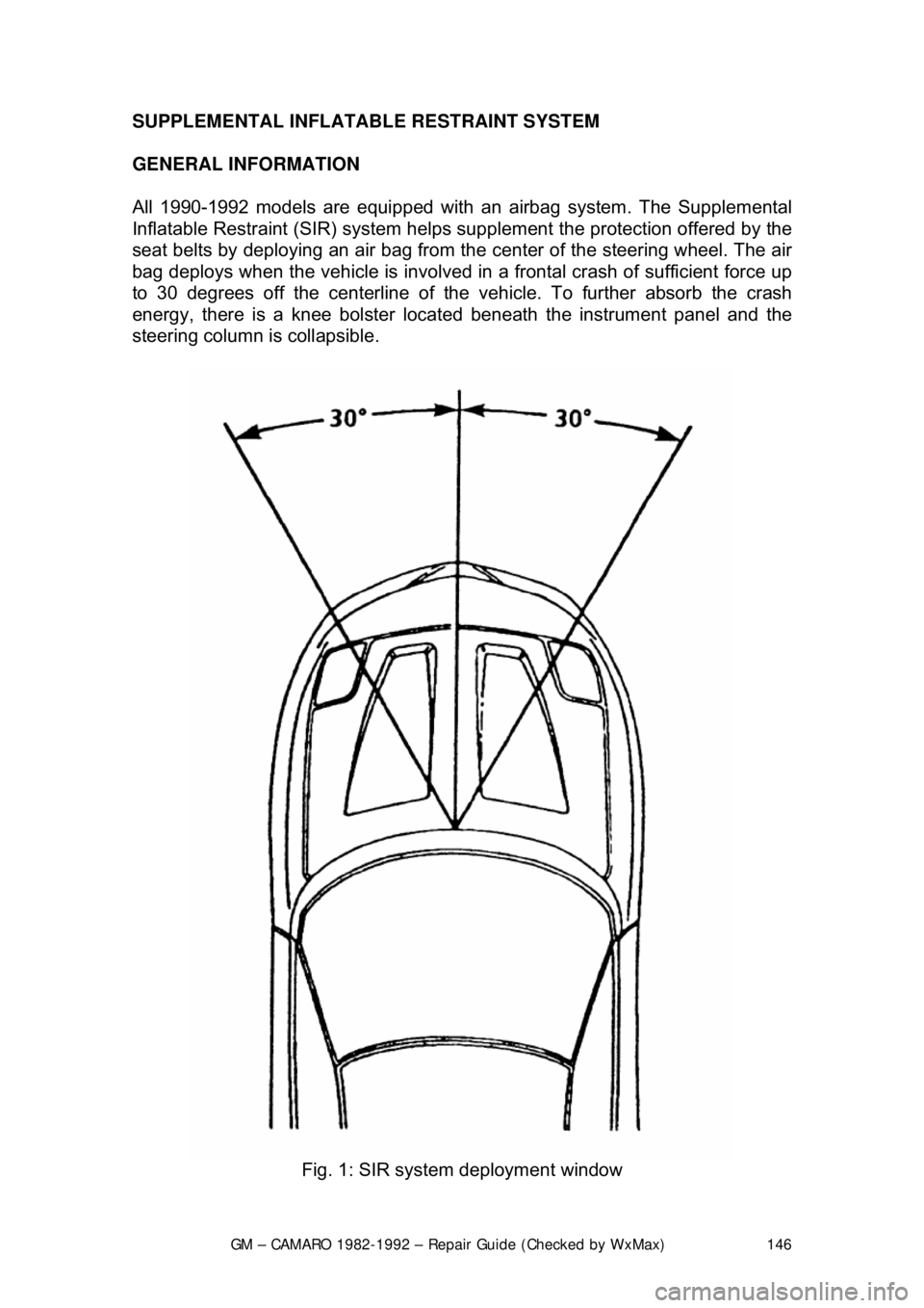
seat belts by deploying an ai r bag from the center of the steering wheel. The air
bag deploys when the vehicle is involved in a frontal crash of sufficient force up
to 30 degrees off the center line of the vehicle. To further absorb the crash
energy, there is a knee bolster located beneath the instrument panel and the
steering column is collapsible.
Fig. 1: SIR system deployment window
Page 338 of 875

GM – CAMARO 1982-1992 – Repair Guide (Checked by WxMax) 338
seal preload. Turn the torque wrenc
h smoothly for several rotations and
record the amount of preload as the a ssembly is turning, not the initial
force required to start the assembly moving.
Preload is measured as the amount of torque required to turn the assembly.
5. Using a suitable tool to hold the pi nion yoke in place, remove the pinion
yoke nut and washer.
6. Place a suitable contai ner under the differential to catch any fluid that
may drain from the rear axle. Using a suitable tool, remove the pinion
flange.
7. Use a suitable tool to remove the pinion seal.
To install: 8. Inspect the seal surface of the pinion flange for tool marks, nicks or
damage and replace, as necessary. Examine the carrier bore and
remove any burrs that might cause leaks around the outside of the seal.
9. Install the seal 0.010 in. (0.2 5mm) below the flange surface using a
suitable seal installer.
10. Apply suitable seal lubricant to t he outer diameter of the pinion flange
and the sealing lip of the new seal.
11. Install the pinion flan ge on the drive pinion by taping with a soft hammer
until a few pinion threads projec t through the pinion flange.
12. Install the washer and pinion fla nge nut. While holding the pinion flange,
tighten the nut a little at a time and turn the drive pinion several
revolutions after each tightening, to set the bearing rollers. Check the
preload each time with a suitable inch pound to rque wrench until the
preload is 5 inch lbs. (0.6 Nm) more then the reading obtained during
disassembly.
13. Install the driveshaft.
14. Install the rear wheels and tires. Check and add the correct lubricant, as
necessary.
AXLE HOUSING
REMOVAL & INSTALLATION 1. Raise the vehicle and support it sa fely. Be sure that the rear axle
assembly is supported safely.
2. Disconnect shock absorbers from ax le. Remove the wheel assemblies.
3. Mark driveshaft and pinion flange, then disconnect driveshaft and support out of the way.
4. Remove brake line junction block bolt at axle housing. If necessary,
disconnect the brake lines at the junction block.
Page 340 of 875

GM – CAMARO 1982-1992 – Repair Guide (Checked by WxMax) 340
10. Install the brake line j
unction block bolt at the ax le housing. Connect any
brake lines that were disconnected.
11. Install and secure the driveshaft a ligning the match marks made earlier.
12. Connect the shock absorbers to the axle and install the wheel
assemblies.
13. Lower the vehicle and replace any lost rear axle fluid.
DIFFERENTIAL ASSEMBLY
REMOVAL & INSTALLATION 1. Raise and safely support the vehicle.
2. Place a suitable contai ner under the differential. Remove the carrier
cover and drain the gear oil.
3. Remove the drive axles.
4. Mark the differential bearing caps L and R to make sure they will be
reassembled in their original location.
5. Using a suitable tool, remove the di fferential carrier. Be careful not to
damage the gasket sealing surface wh en removing the unit. Place the
right and left bearing outer races of the side bearing assemblies and
shims in sets with the marked different ial bearings caps so they can be
reinstalled in their original positions.
To install: 6. Inspect the differential carrier housi ng for foreign material. Check the ring
and pinion for chipped teeth, exce ssive wear and scoring. Check the
carrier bearings visually and by feel . Clean the differential housing and
replace components, as necessary.
7. Install the differential carrier. C heck the carrier bearing preload along
with the ring and pinion backlash, then adjust, as necessary. Tighten the
differential bearing cap bolts to 55 ft. lbs. (75 Nm) except on Borg-
Warner rear axles which are ti ghtened to 40 ft. lbs. (54 Nm).
8. Install the axles.
9. Install the carrier cover using a new gasket. Tighten the carrier cover
bolts to 20 ft. lbs. (27 Nm). Add the proper type and quantity of gear oil to
axle assembly.
Page 381 of 875

GM – CAMARO 1982-1992 – Repair Guide (Checked by WxMax) 381
It is not necessary to remove the radi
ator hose from the thermostat housing.
4. Remove the two retaining bolts from the thermostat housing and remove
the thermostat.
To install: 5. Using a new gasket, install the thermostat and housing.
6. Tighten the bolts to 21 ft lbs. (28 Nm).
7. Fill and bleed t he cooling system.
INTAKE MANIFOLD
REMOVAL & INSTALLATION
When servicing all vehicles, be absolutel y sure to mark vacuum hoses and
wiring so that these items may be properly reconnected during installation. Also,
when disconnecting fitting lines (fuel lines, power brake vacuum lines,
transmission and engine cooler lines, etc.), always use two flare nut (or line)
wrenches. Hold the wrench on the large fitti ng with pressure on the wrench as if
you were tightening the fitting (clockw ise), THEN loosen and disconnect the
smaller fitting from the larger fitting. If this is not done, damage to the line will
result. Always relieve fuel system pressure before disconnecting lines.
CAUTION - When draining the coolant, keep in mind that cats and dogs are
attracted by the ethylene gl ycol antifreeze, and are quite likely to drink any that
is left in an uncovered container or in puddles on the ground. This will prove
fatal in sufficient quantity. Always drai n the coolant into a sealable container.
Coolant should be reused unless it is contaminated or several years old.
2.5L ENGINE
Fig. 1: Intake manifold bol t torque sequence for 2.5L engine
1. Disconnect the negative batte ry cable at the battery.
2. Remove the air cleaner assembly.
3. Remove the PCV valve and hose.
4. Drain the cooling system.
5. Disconnect the fuel lines from the Throttle Body Injection (TBI) unit.
6. Mark and disconnect the vacuum li nes and the electrical connections
from the TBI unit.
7. Disconnect the linkage from the TBI unit (throttle, downshift, and/or
cruise control, as applicable).
8. Disconnect the coolant inlet and outlet hoses from the intake manifold.
9. Remove the air conditioning co mpressor support brackets and the
compressor. DO NOT disconnect the refrigerant lines from the
compressor. Lay the compressor aside.
10. Remove the manifold attachi ng bolts and remove the manifold.
To install:
Page 386 of 875

GM – CAMARO 1982-1992 – Repair Guide (Checked by WxMax) 386
FUEL INJECTION
1. Remove the air cleaner.
2. Drain the radiator.
3. Disconnect: a. Battery cables at the battery.
b. Upper radiator and heater hoses at the manifold.
c. Crankcase ventilation hoses as required.
d. Fuel line at the carburetor.
e. Accelerator linkage.
f. Vacuum hose at the distributor, if equipped.
g. Power brake hose at the car buretor base or manifold, if
applicable.
h. Temperature sending switch wires.
4. Remove the distributor cap and scribe the rotor position relative to the
distributor body, and engine.
5. Remove the distributor.
6. If applicable, remove the alternator upper bracket. As required, remove
the air cleaner bracket, and accelerator bellcrank.
7. Remove the manifold-to-head attachi ng bolts, then remove the manifold
and carburetor as an assembly.
8. Mark and disconnect all emission re lated items (e.g.: wiring, vacuum
hoses, etc.) which are connected to manifold mounted items.
9. If the manifold is to be replaced , transfer the carburetor (and mounting
studs), water outlet and thermostat (use a new gasket) heater hose
adapter, EGR valve (use new gasket) and, if applicable, TVS switch(s)
and the choke coil.
To install: 10. Before installing the manifold, thoroughly clean the gasket and sealing
surfaces of the cylinder heads and manifold.
11. Install the manifold end seals, folding the tabs if applicable, and the
manifold/head gaskets, using a s ealing compound around the water
passages.
Make sure that the new manifold gaskets match the old ones EXACTLY.
12. When installing the manifold, care should be taken not to dislocate the
end seals. It is helpful to use a pilo t in the distributor opening. Tighten the
manifold bolts to 30 ft. lbs. (40 Nm) for 5.0L or 20-25 ft. lbs. (27-34 Nm)
for 2.8L in the sequence illustrated.
13. Install the distributor with the rotor in its original location as indicated by
the scribe line. If the engi ne has been disturbed, refer to the previous
Distributor Removal and Installation procedure.
14. If applicable, install the alter nator upper bracket and adjust the belt
tension.
15. Connect all disconnected components at their original locations.
16. Fill the cooling system, start the engine, check for leaks and adjust the
ignition timing and carburetor idle speed and mixture.
Page 395 of 875

GM – CAMARO 1982-1992 – Repair Guide (Checked by WxMax) 395
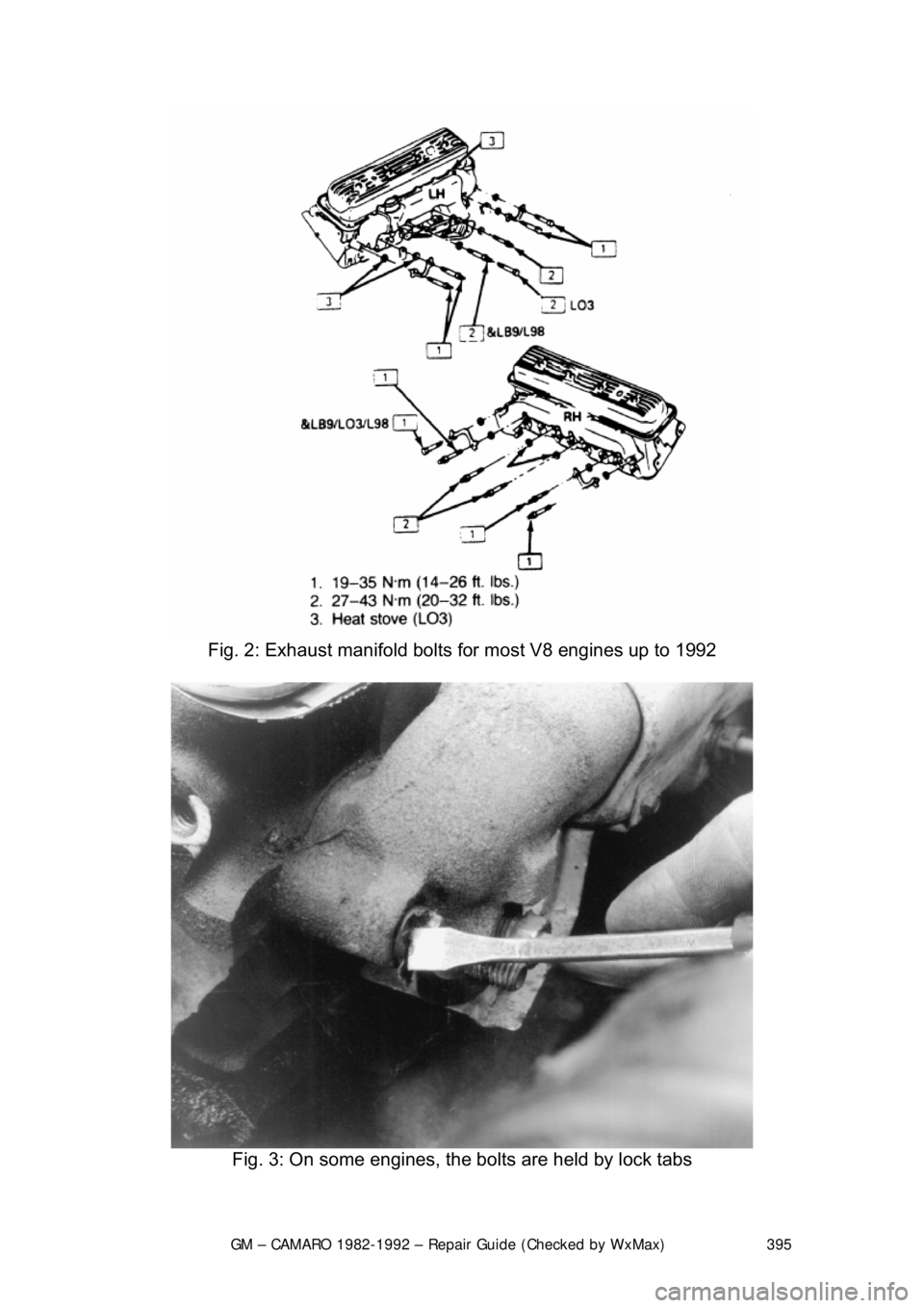
Fig. 2: Exhaust manifold bolts for most V8 engines up to 1992
Fig. 3: On some engines, the bolts are held by lock tabs