distributor CHEVROLET CAMARO 1982 Repair Guide
[x] Cancel search | Manufacturer: CHEVROLET, Model Year: 1982, Model line: CAMARO, Model: CHEVROLET CAMARO 1982Pages: 875, PDF Size: 88.64 MB
Page 346 of 875
GM – CAMARO 1982-1992 – Repair Guide (Checked by WxMax) 346
battery, electricity is forced into the battery
, and the battery is returned to its fully
charged state.
Alternators are used on the modern autom obiles for they are lighter, more
efficient, can rotate at higher speeds and have fewer brush problems. In an
alternator, the field rotates while al l the current produced passes only through
the stators windings. The brushes bear agains t continuous slip rings rather than
a commutator. This causes the current produced to periodically reverse the
direction of its flow. Diodes (electrica l one-way switches) block the flow of
current from traveling in t he wrong direction. A series of diodes is wired together
to permit the alternating flow of the st ator to be converted to a pulsating, but
unidirectional flow at the alternator out put. The alternator's field is wired in
series with the voltage regulator.
Please refer to Engine Performance & Tune-up for ignition system testing
procedures.
IGNITION COIL
REMOVAL & INSTALLATION
INTERNALLY MOUNTED COIL 1. Disconnect and label the wires from cap.
2. Remove the distributor cap from the distributor.
3. On the distributor cap, remove t he coil cover attaching screws and the
cover.
4. Remove the ignition coil attaching screws and lift the coil from the cap.
To install: 5. Position the coil and secure it with the attaching screws. Be sure to install
the carbon button and rubber disc first.
6. Install the coil cover and attaching screws.
7. Install the distributor cap.
8. Connect the wires to the cap.
EXTERNALLY MOUNTED COIL 1. Label and disconnect the wires from the coil.
2. Remove the ignition coil mounting bolts and the coil.
To install: 3. To install, position the coil into place and se cure it with the mounting
bolts.
4. Connect the wires to the coil.
IGNITION MODULE
Page 347 of 875
GM – CAMARO 1982-1992 – Repair Guide (Checked by WxMax) 347
REMOVAL & INSTALLATION
1. Disconnect the wires from the cap.
2. Remove the distributor cap.
3. Remove the two module attaching screws and capacitor attaching screw.
Lift module, capacitor and harnes s assembly from base.
4. Disconnect wiring harness.
To install: 5. Apply silicone grease underneath the module. This grease is necessary
for ignition module cooling.
6. Connect the wiring harness.
7. Install the module and attaching screws.
8. Install the distributor cap and wires.
DISTRIBUTOR
REMOVAL & INSTALLATION
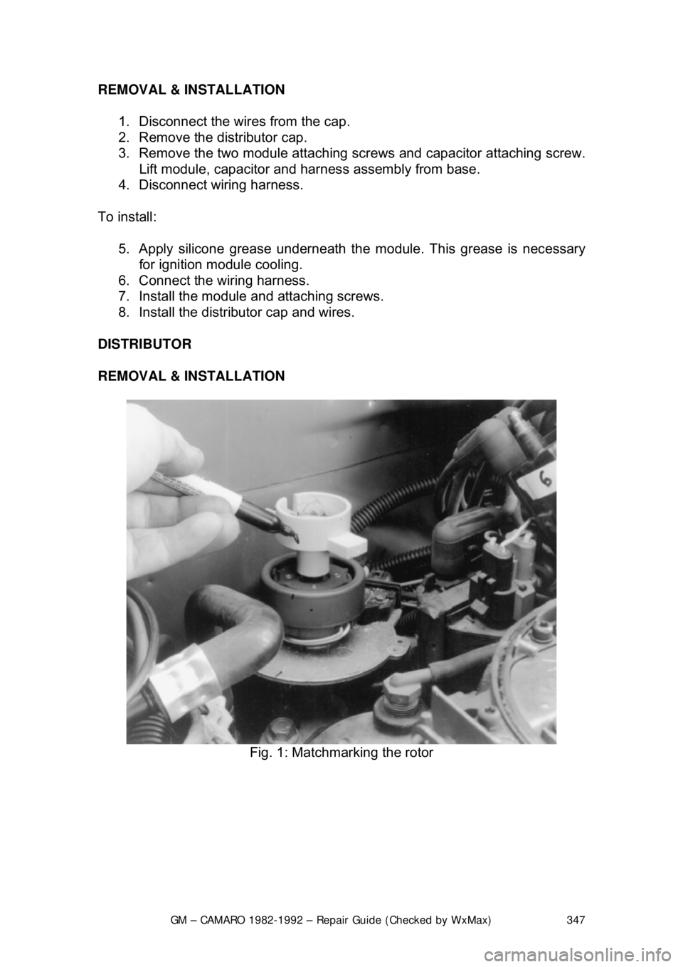
Fig. 1: Matchmarking the rotor
Page 349 of 875
GM – CAMARO 1982-1992 – Repair Guide (Checked by WxMax) 349
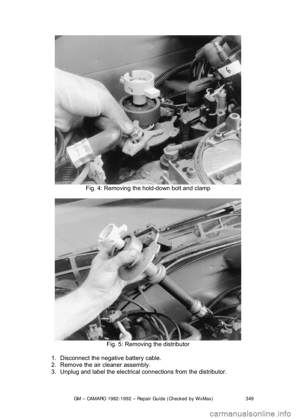
Fig. 4: Removing the hold-down bolt and clamp
Fig. 5: Removing the distributor
1. Disconnect the negative battery cable.
2. Remove the air cleaner assembly.
3. Unplug and label the electrical connections from the distributor.
Page 350 of 875
GM – CAMARO 1982-1992 – Repair Guide (Checked by WxMax) 350
4. Remove the distributor cover and wi
re retainer, if equipped. Turn the
retaining screws counterclockwise and remove the cap.
5. Mark the relationship of the roto r to the distributor housing and the
housing relationship to the engine.
6. Remove the distributor reta ining bolt and hold-down clamp.
7. Pull the distri butor up until the rotor just stops turning counterclockwise
and again note the position of the rotor.
8. Remove the distribut or from the engine.
To install: 9. Insert the distributor into the engine, with the rotor aligned to the last
mark made, then slowly install the dist ributor the rest of the way until all
marks previously made are aligned.
10. Install the distributor hold- down clamp and retaining bolt.
11. If removed, install the wiring harness retainer and secondary wires.
12. Install the distributor cap.
13. Engage the wire connections on t he distributor. Make certain the
connectors are fully seated and latched.
14. Reconnect the negative battery cable.
If the engine was accidentally cranked afte r the distributor was removed, the
following procedure can be used during installation.
15. Remove the No. 1 spark plug.
16. Place a finger over the spark pl ug hole. Have a helper turn the engine
slowly using a wrench on the crankshaft bolt until compression is felt. \
17. Align the timing mark on the pulley to 0 on the engine timing indicator.
18. Turn the rotor to point to the No . 1 spark plug tower on the distributor
cap.
19. Install the distributor assembly in the engine and ensure the rotor is
pointing toward the No. 1 spark plug tower.
20. Install the cap and spark plug wires.
21. Check and adjust engine timing.
ALTERNATOR
DESCRIPTION
An alternator differs from a DC shunt generator in that the armature is
stationary, and is called the stator, while the field rotates and is called the rotor.
The higher current values in the alternator's stator are conducted to the external
circuit through fixed leads and connecti ons, rather than through a rotating
commutator and brushes as in a DC generator. This eliminates a major point of
maintenance.
The rotor assembly is supported in the drive end frame by a ball bearing and at
the other end by a roller bearing. These bearings are lubricated during
assembly and require no main tenance. There are six diodes in the end frame
assembly. These diodes are electrical check valves that also change the
Page 364 of 875
GM – CAMARO 1982-1992 – Repair Guide (Checked by WxMax) 364
5. Drain the radiator and remove t
he radiator hoses. Disconnect the heater
hoses and the transmission cooler lines.
6. Remove the upper half of the radi ator shroud, if equipped with a manual
transmission. Remove the radiator and fan shroud assembly, if equipped
with an automatic transmission.
7. Disconnect the throttle linkage, includi ng the cruise control detent cable.
8. Remove the air conditioning compressor and lay aside.
Do not disconnect the air conditioning lines.
9. Disconnect the power steering pump and drain the fluid into a suitable
container. Remove the vacuum brake booster line.
10. Remove the distributor cap and spark plug wires.
11. Disconnect the engine electrical connection at the bulkhead connection
and disconnect any necessary vacuum hoses.
12. Working inside the vehicle, re move the right-hand hush panel and
disconnect the ECM harness at the EC M. Raise and safely support the
vehicle. Remove the right fenderwell splash shield and feed the harness
through the fenderwell.
13. Disconnect the exhaust pipes at the exhaust manifolds and remove
exhaust system from the vehicle.
14. Remove the flywheel cover and remo ve the converter bolts, if equipped
with automatic transmission.
15. Disconnect the transmission an d starter wire connections.
16. Remove the bellhousing and t he motor mount through-bolts.
17. Disconnect the clutch fork return spring, if equipped with a manual
transmission. Lower the vehicle.
18. Relieve the fuel system pressu re. Disconnect the fuel lines.
19. Support the transmission with a suit able jack. Attach an engine lifting
device.
20. Remove the engine assembly.
To install: 21. Position the engine assembly in the vehicle.
22. Attach the motor mount to engine br ackets and lower the engine in place.
Remove the engine lifting device and the transmission jack.
23. Raise and support the vehicle safely.
24. Install the motor mount through-bolts and tighten the nuts to specification. Install t he bellhousing bolts and tight en to 35 ft. lbs. (47
Nm).
25. On vehicles with automatic transmissi on, install the converter to flywheel
attaching bolts to 46 ft. lbs. (63 Nm).
26. Install the flywheel splash shield and tighten to 89 inch lbs. (10 Nm).
Install the clutch return spring, if equipped with manual transmission.
27. Connect the starter wires and the fuel lines.
28. Install the exhaust system.
29. Lower the vehicle.
30. Install the power steering pump and the air conditioning compressor.
Page 365 of 875
GM – CAMARO 1982-1992 – Repair Guide (Checked by WxMax) 365
31. Connect the bulkhead harness connec
tor, wires and hoses. Reroute the
ECM harness in its original location. Install the hush panel and fenderwell
splash panel.
32. Install the radiator, fan and fan sh roud. Connect the radiator and heater
hoses, along with the transmission cooler lines.
33. Connect the vacuum brake booster li ne, the throttle linkage and cruise
control cable. Install the distributor cap.
34. Fill the cooling system with the proper type and amount of coolant and
the crankcase with the proper type of oil to the correct level.
35. Install the water pump drive bel t, the air cleaner duct and the hood.
36. Connect the negative battery cable, st art the engine and check for leaks.
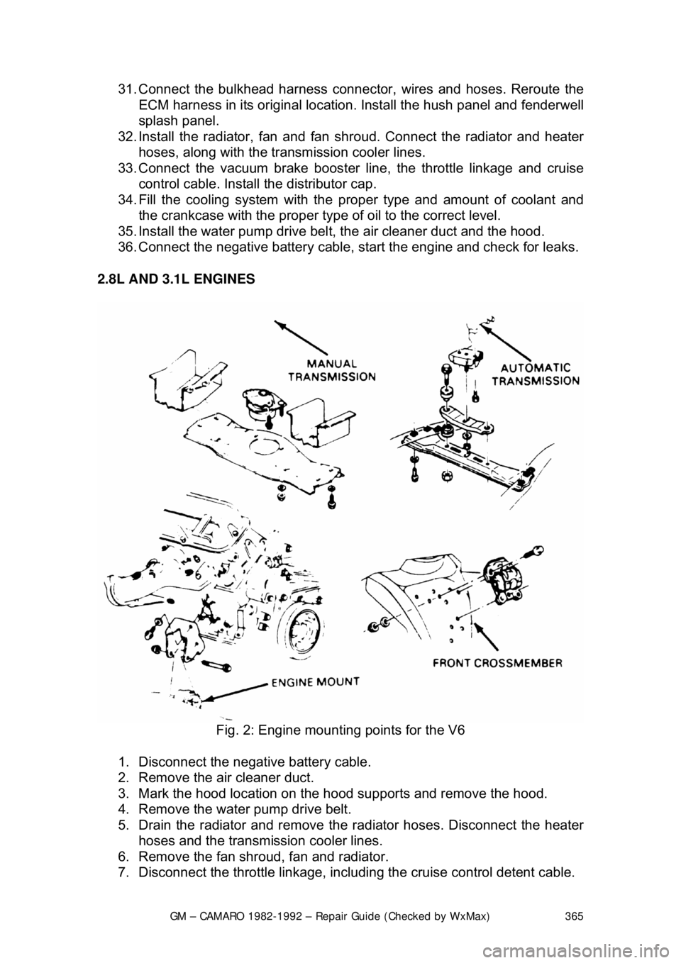
2.8L AND 3.1L ENGINES
Fig. 2: Engine mountin g points for the V6
1. Disconnect the negative battery cable.
2. Remove the air cleaner duct.
3. Mark the hood location on the hood supports and remove the hood.
4. Remove the water pump drive belt.
5. Drain the radiator and remove t he radiator hoses. Disconnect the heater
hoses and the transmission cooler lines.
6. Remove the fan shroud, fan and radiator.
7. Disconnect the throttle linkage, includi ng the cruise control detent cable.
Page 366 of 875
GM – CAMARO 1982-1992 – Repair Guide (Checked by WxMax) 366
8. Remove the air conditioning co
mpressor and lay aside. Remove the
power steering pump and lay aside.
Do not disconnect the air conditioning or power steering lines.
9. Remove the vacuum brake booster line.
10. Remove the distributor cap and spark plug wires.
11. Disconnect the necessary elec trical connections and hoses.
12. Raise and safely support the vehicle.
13. Disconnect the exhaust pipes at the exhaust manifolds.
14. Remove the flywheel cover and remove the converter bolts.
15. Disconnect the star ter wire connections.
16. Remove the bellhousing and t he motor mount through-bolts.
17. Lower the vehicle.
18. Relieve the fuel system pressu re. Disconnect the fuel lines.
19. Support the transmission with a suit able jack. Attach an engine lifting
device.
20. Remove the engine assembly.
To install: 21. Position the engine assembly in the vehicle.
22. Attach the motor mount to engine br ackets and lower the engine in place.
Remove the engine lifting device and the transmission jack.
23. Raise and support the vehicle safely.
24. Install the motor mount through-bolts and tighten the nuts to 50 ft. lbs. (68 Nm). Install the bellhousing bolts and tighten to 35 ft. lbs. (47 Nm).
25. On vehicles with automatic transmissi on, install the converter to flywheel
attaching bolts to 46 ft. lbs. (63 Nm).
26. Install the flywheel splash shield and tighten to 89 inch lbs. (10 Nm).
27. Connect the starter wires and the fuel lines.
28. Install the exhaust pipe on the exhaust manifold.
29. Lower the vehicle.
30. Install the power steering pump and the air conditioning compressor.
31. Connect the necessary wires and hoses.
32. Install the radiator, fan and fan sh roud. Connect the radiator and heater
hoses and the transmission cooler lines.
33. Connect the vacuum brake booster li ne, the throttle linkage and cruise
control cable. Install the distributor cap.
34. Fill the cooling system with the proper type and amount of coolant and
the crankcase with the proper type of oil to the correct level.
35. Install the water pump drive bel t, the air cleaner duct and the hood.
36. Connect the negative battery cable, st art the engine and check for leaks.
Page 367 of 875
GM – CAMARO 1982-1992 – Repair Guide (Checked by WxMax) 367
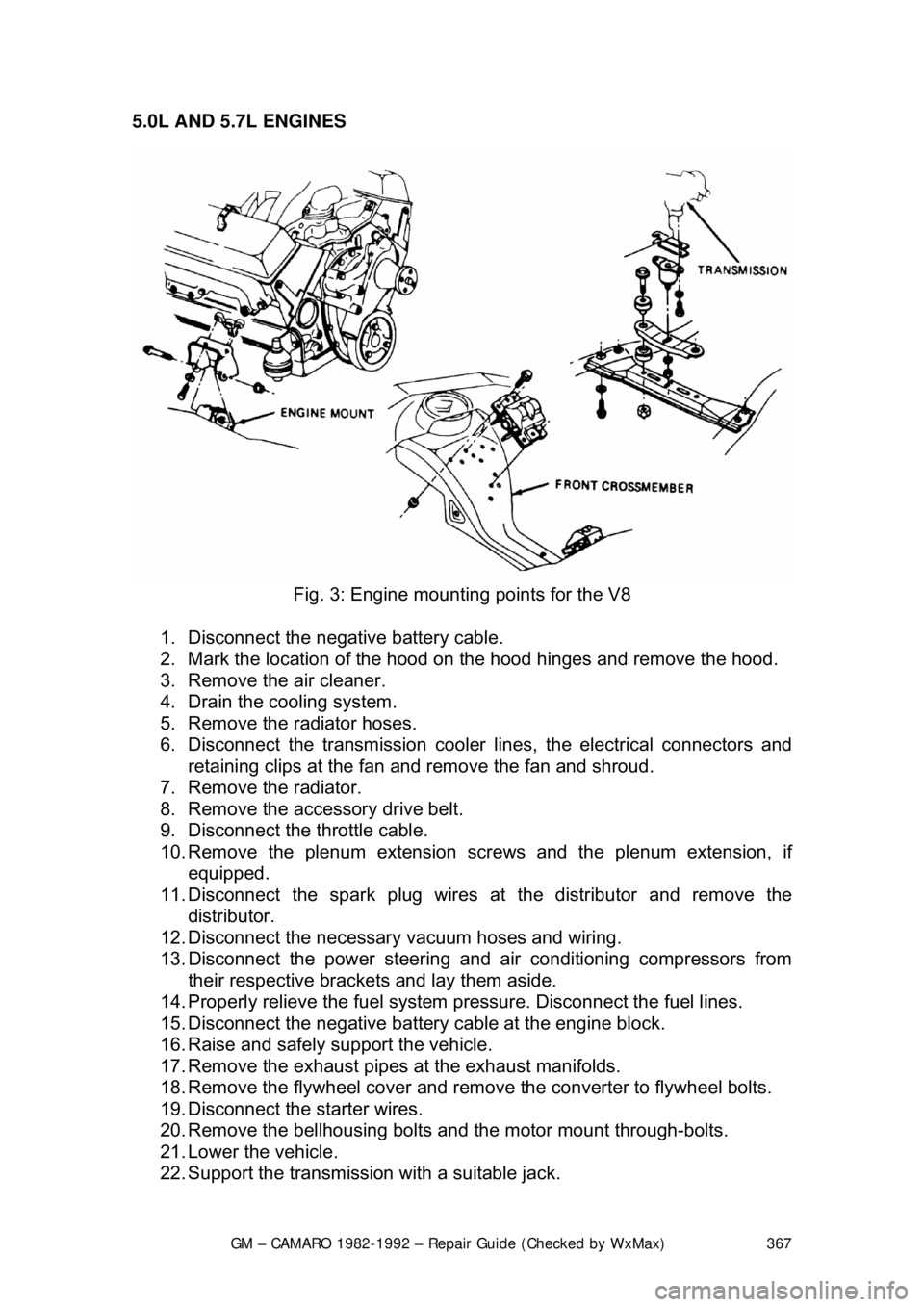
5.0L AND 5.7L ENGINES
Fig. 3: Engine mountin g points for the V8
1. Disconnect the negative battery cable.
2. Mark the location of the hood on the hood hinges and remove the hood.
3. Remove the air cleaner.
4. Drain the cooling system.
5. Remove the radiator hoses.
6. Disconnect the transmission cooler li nes, the electrical connectors and
retaining clips at the fan and remove the fan and shroud.
7. Remove the radiator.
8. Remove the accessory drive belt.
9. Disconnect the throttle cable.
10. Remove the plenum extension scr ews and the plenum extension, if
equipped.
11. Disconnect the spark plug wires at the distributor and remove the
distributor.
12. Disconnect the necessary vacuum hoses and wiring.
13. Disconnect the power steering and air conditioning compressors from
their respective brackets and lay them aside.
14. Properly relieve the fuel system pressure. Disconnect the fuel lines.
15. Disconnect the negative battery cable at the engine block.
16. Raise and safely support the vehicle.
17. Remove the exhaust pipes at the exhaust manifolds.
18. Remove the flywheel cover and remove the converter to flywheel bolts.
19. Disconnect the starter wires.
20. Remove the bellhousing bolts and the motor mount through-bolts.
21. Lower the vehicle.
22. Support the transmission with a suitable jack.
Page 368 of 875
GM – CAMARO 1982-1992 – Repair Guide (Checked by WxMax) 368
23. Remove the AIR/converter bracket
and ground wires from the rear of the
cylinder head.
24. Attach a suitable lifting devic e and remove the engine assembly.
To install: 25. Position the engine assembly in the vehicle.
26. Attach the motor mount to engine brackets and lower the engine into
place.
27. Remove the engine lifting device and the transmission jack.
28. Raise and safely support the vehicle.
29. Install the motor mount through-bolts and tighten to 50 ft. lbs. (68 (Nm).
30. Install the bellhousing bolts and tighten to 35 ft. lbs. (47 Nm).
31. On vehicles with automatic transmissi on, install the converter to flywheel
bolts. Tighten the bolts to 46 ft. lbs. ( 63 Nm). Install the flywheel cover.
32. Connect the starter wires and the fuel lines.
33. Connect the exhaust pipe at the exhaust manifold.
34. Lower the vehicle.
35. Connect the necessary wires and hoses.
36. Install the power steering pump and air conditioning compressor in their
respective brackets.
37. Install the radiator, fan and fan sh roud, radiator hoses and heater hoses.
38. Connect the transmission cooler lines and cooling fan electrical
connectors.
39. Install the distributor.
40. Install the plenum ex tension, if equipped.
41. Fill the cooling system with the proper type and quantity of coolant and
the crankcase with the proper type of oil to the correct level.
42. Install the air cleaner and the hood.
43. Connect the negative battery cable, start the engine, check for leaks and
check timing.
Page 373 of 875
GM – CAMARO 1982-1992 – Repair Guide (Checked by WxMax) 373
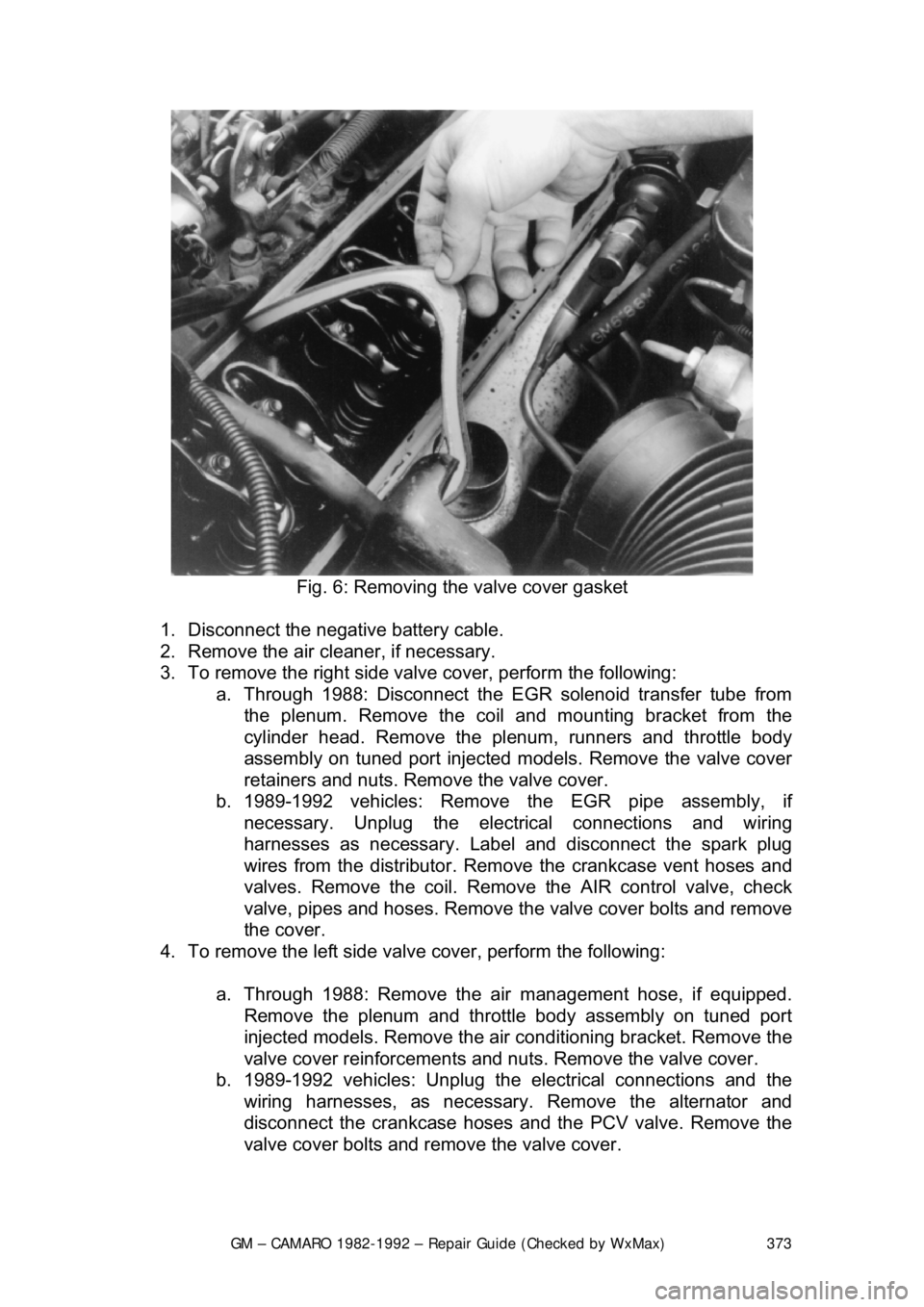
Fig. 6: Removing the valve cover gasket
1. Disconnect the negative battery cable.
2. Remove the air cleaner, if necessary.
3. To remove the right side valv e cover, perform the following:
a. Through 1988: Disconnect the EG R solenoid transfer tube from
the plenum. Remove the coil and mounting bracket from the
cylinder head. Remove the plenum, runners and throttle body
assembly on tuned port injected models. Remove the valve cover
retainers and nuts. Remove the valve cover.
b. 1989-1992 vehicles: Remove the EGR pipe assembly, if
necessary. Unplug the electrical connections and wiring
harnesses as necessary. Label and disconnect the spark plug
wires from the distributor. Remo ve the crankcase vent hoses and
valves. Remove the coil. Remove the AIR control valve, check
valve, pipes and hoses. Remove t he valve cover bolts and remove
the cover.
4. To remove the left side valve cover, perform the following:
a. Through 1988: Remove the air management hose, if equipped.
Remove the plenum and throttle body assembly on tuned port
injected models. Remove the air conditioning bracket. Remove the
valve cover reinforcements and nuts. Remove the valve cover.
b. 1989-1992 vehicles: Unplug the electrical connections and the
wiring harnesses, as necessary . Remove the alternator and
disconnect the crankcase hoses and the PCV valve. Remove the
valve cover bolts and remove the valve cover.