bulb CHEVROLET CAVALIER 1984 1.G Owners Manual
[x] Cancel search | Manufacturer: CHEVROLET, Model Year: 1984, Model line: CAVALIER, Model: CHEVROLET CAVALIER 1984 1.GPages: 105, PDF Size: 24.23 MB
Page 25 of 105
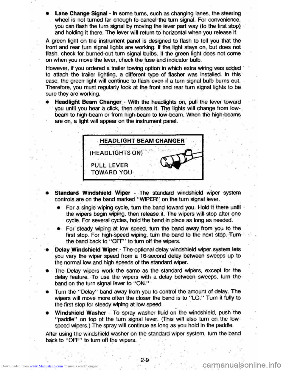
Downloaded from www.Manualslib.com manuals search engine • Lane Change Signal -In some turns, such as changing lanes, the steering wheel tS not turned far enough to cancel the turn signal. For convenience, you can flash the turn signal by moving the lever part way (to the first stop)
and holding it there. The lever will return to horizontal when you release it.
A green light on the instrument panel is designed to flash to tell you that the
front
and rear turn signal lights are working. If the light stays on, but does not flash, check for burned-out turn signal bulbs. If the green light does not come
on when
you move the lever, check the fuse and indicator bulb.
However, if you ordered a trailertowing·optiOil.·in which extra wiring was added to attach the trailer lighting, a different type of flasher was installed. In this
case, the green light will continue to flash even if a turn signal bulb burns out.
Therefore, you must regularly look at the front
and rear turn signal lights to be
sure they are working.
• Headlight Beam Changer -With the headlights on, pull the lever toward you until you hear a click, then release it. The lights will change from Iow
beam to high-beam or from high-beam to low-beam. When the high-beams
are
on, a light will appear on the instrument panel.
HEADLIGHT BEAM CHANGER
(HEADLIGHTS ON)
PULL LEVER
TOWARD YOU
• Standard Windshield Wiper -The standard Windshield wiper system
con
ols are on the band marked "WIPER" on the turn signal lever.
• For a single wiping cycle, turn the band toward you. Hold it there until
the wipers begin
Wiping, then release.it. The wipers will stop after one
cycle. For several cycles, hold the band in place as long as needed.
• For steady wiping at low speed, turn the band away from you to the
first stop. For high-speed wiping, turn the band to the next stop. Turn
the band back to
"OFF" to turn off the wipers.
• Delay Windshield Wiper -The optional delay windshield wiper system lets you vary the wiper speed from a 16-second delay between sweeps up to
the normal
low and high speeds of the standard wiper.
• The Delay wipers work the same as the standard wipers, except for the
delay feature. To use the wipers with a delay between sweeps, turn the
band on the turn signal lever to
"ON."
• Turn the "Delay" band away from you to control the amount of delay. The
wipers will move more often the closer the band is to "LO." Turn it fully to
the first stop for steady wiping at
low speed.
• Windshield Washer -To spray washer fluid on the windshield, pUSh the "paddle" on top of the turn signal lever. (This will also turn on the low~ speed wipers.) The spray will continue as long as you hold in the paddle.
After using the windshield washer
on the standard wiper system, turn the band
back to "OFF" to turn off the wipers.
2-9
Page 37 of 105
Downloaded from www.Manualslib.com manuals search engine • Amount of fuel required for fill-up may not exactly correspond to gage.
• Needle may not move away from FULL until some time after fill-up.
• Needle may move during turns; stops and accelerations.
When the ignition switch is turned to the OFF position, the needle will not
necessarily return
all the way to the EMPTY mark.
Oil Pressure Light
When the ignition is turned to "Run," the "Oil" warning light appears until the
engine is started. Thereafter, the light should be off unless there is insufficient
oil pressure or engine idle speed is below normal. If the light should come on
at any time while driving (other than momentarily at idle speed or after a
sudden stop), stop immediately and investigate the cause of
low oil pressure.
This could possibly be caused by low oil level in the crankcase. Engine
operation with low oil pressure will 9ause damage to the engine.
Engine Coolant Temperature Light
This light is located in the instrument cluster and is designed to come on to warn the driver that the engine coolant has overheated and immediate
action is required to correct the condition. As a check that the bulb and its
circuit are working, the light will come on during engine starting; if it does not,
have it repaired
promptly. If the light comes on at any other time, see "Engine
Cooling System Overheating" in "In Case of Emergency," Section 3 of this manual.
CAUTION: It the Engine Coolant Temperature Light shows an overheat condition or you have other reason to suspect the engine may be overheating, continued operation of the engine EVEN FOR A SHORT TIME may result in a fire and the risk of personal injury and/or severe vehicle damage. Take immediate action as outlined under "Engine Cooling System Overheating" in "In Case of Emergency," Section 3.
Generator Indicator Light
The VOLT light is designed to come on when the ignition key is in the "RUN" position, but before the engine is started. After the engine starts, the light
should go out and remain out. If the light remains· on when engine is running,
have your authorized
dealer locate and correct the trouble as soon as possible.
Shift Indicator Light
The Shift Indicator Light is covered in the "Manual Transaxle" information in
this section.
"Check Engine" Light
Most gasoline engine vehicles sold in the Unijed States (and some vehicles
sold
in Canada) have the Computer Command Control system.
Vehicles with the Computer Command Control system include a "CHECK
ENGINE" light
on the instrument panel designed to indicate the need for
system service. It will come on during engine starting to let you know the bulb
is working. (The light will stay on a short time after the engine starts.)
2-21
Page 38 of 105
Downloaded from www.Manualslib.com manuals search engine Have the system repaired n the "CHECK ENGINE" light does not come on during engine starting. If the light comes on, either intermittently or
continuously while driving, service to the Computer Command Control system
is required. AHhough in most cases the vehicle is drivable, and does not
require towing, see your authorized
dealer as soon as possible for service of
the system.
Continued driving without having the Computer
Command Control system serviced could cause damage to the emission control system. It could also affect fuel economy and drivability.
See also "Computer Command Control system" in Section 5 of this manual.
Brake System Warning Light
The regular braking system is a dual system designed so that one part will
provide some braking if there is a
loss of hydraulic pressure in the other part of
the system. The system has a
"BRAKE" warning light located in the
instrument panel. The "BRAKE" light is designed to come on briefly during
engine starting so you can check that the bulb is okay. To serve as a reminder,
the
light should stay on when the parking brake is not fully released and the
ignition is
on. Have the system repaired if the light does not come on when it should. This warning light does not do away with the need for brake inspection
and maintenaflce. The brakelluid level must be checked regularly. See your
Maintenance Schedule folder for other brake checks.
I! the light remains on aller engine start up or comes on during operation of the vehicle, it may mean that there is something wrong with part of the brake
system.
What
to do:
1. Check to see that the parking brake has been released. I! it has been:
2. Pull off the road and stop carefully. Remember that:
• Stopping distances may be longer.
•
You may have to push harder on the pedal.
•
The pedal may go down farther than normal.
3. Tryout the brakes by starting and stopping on the road shoulder--then:
• I! you judge it to be safe, drive cautiously at a safe speed to the
nearest dealer for repair. Or,
• Have vehicle towed to the nearest dealer for repair.
Continued driving without getting necessary repairs
could be dangerous.
Tachometer
The optional tachometer indicates the speed of the engine in revolutions per
minute. The indicated number, times
100, gives the engine speed. Operating
the engine with the tachometer reading in the color-coded high-speed area
could lead to serious engine damage.
Voltmeter
When the engine is operating, the voltmeter indicates the electrical system
voltage. During minimum electrical load, the pointer will read to the right of the
center.
As the electrical load is increased, or in stop-and-go driving, the pointer
will rotate to the Ieli. A meter reading continuously in the left or right zone
indicates
an electrical system failure. Cause of the failure should be determined and corrected.
2-22
Page 75 of 105
Downloaded from www.Manualslib.com manuals search engine NOTICE: H you need to replace the fuel cap, use only a cap specified for your model. An incorrect fuel cap can result in a serious maHunction of the fuel system or emission control system. You can get a correct replacement cap from your dealer.
CATALYTIC CONVERTER
The catalytic converter is an emission control device added to the exhaust system to reduce exhaust gas pollutants. The converter contains
a ceramic material coated with noble metal catalysts. To prevent contamination
and loss of effectiveness of the catalysts. unleaded gasoline must be used.
Unleaded
gasoline also reduces spark plug fouling, exhaust system corrosion and engine oil deterioration. Leaded gasoline will also damage the oxygen
sensor
in the Computer Command Control system which could affect emission
control.
To help prevent damage:
1. Keep your engine properly maintained. Engine malfunctions involving the
electrical, carburetion, electronic fuel injection or ignition systems may
result in unusually high catalytic converter and exhaust system
temperatures which, under extreme malfunctioning conditions, may ignite
interior floor ·covering materials above the converter. Do not keep driving
your vehicle if you detect engine misfire, noticeable loss of
performance, or other unusual operating conditions. Instead, have it
serviced promptly. See the Maintenance Schedule folder for information on inspecting and maintaining the engine, exhaust system, and other
components.
2. Do not push or tow this vehicle to start it. This may result in unusually
high catalytic converter
and exhaust system temperatures which under
extreme conditions may ignite interior floor-covering material above the
converter.
Disregarding these instructions
could damage the catalytic converter, the vehicle, or nearby property and affect warranty coverage.
COMPUTER COMMAND CONTROL SYSTEM
Most vehicles sold in the United States (and some vehicles sold in Canada)
have the Computer Command Control system.
The Computer Command Control system monitors the exhaust stream with
an oxygen sensor. Based on sensor signals, the electronic control module adjusts
the air-fuel ratio
as needed. It is very important to use only unleaded
gasoline in vehicles equipped with the Computer Command Control system.
Leaded gasoline will damage the oxygen sensor,
and may affect emission
control.
"Check Engine" Light
Most vehicles sold in the United States (and some vehicles sold in Canada)
have the Computer Command Control system.
Vehicles
.with the Computer Command Control system, include a "CHECK
ENGINE" light
on the instrument panel designed to indicate the need for
system service. It will come on during engine starting to let you know the bulb
is working. (The
light will stay on a short time aiter the engine starts.) Have the
system repaired if the "CHECK ENGINE" light does not come on during engine
starting.
If the light comes on, either intermittently or continuously while driving,
service to the Computer Command Control system is required. Although in
5-2
Page 94 of 105
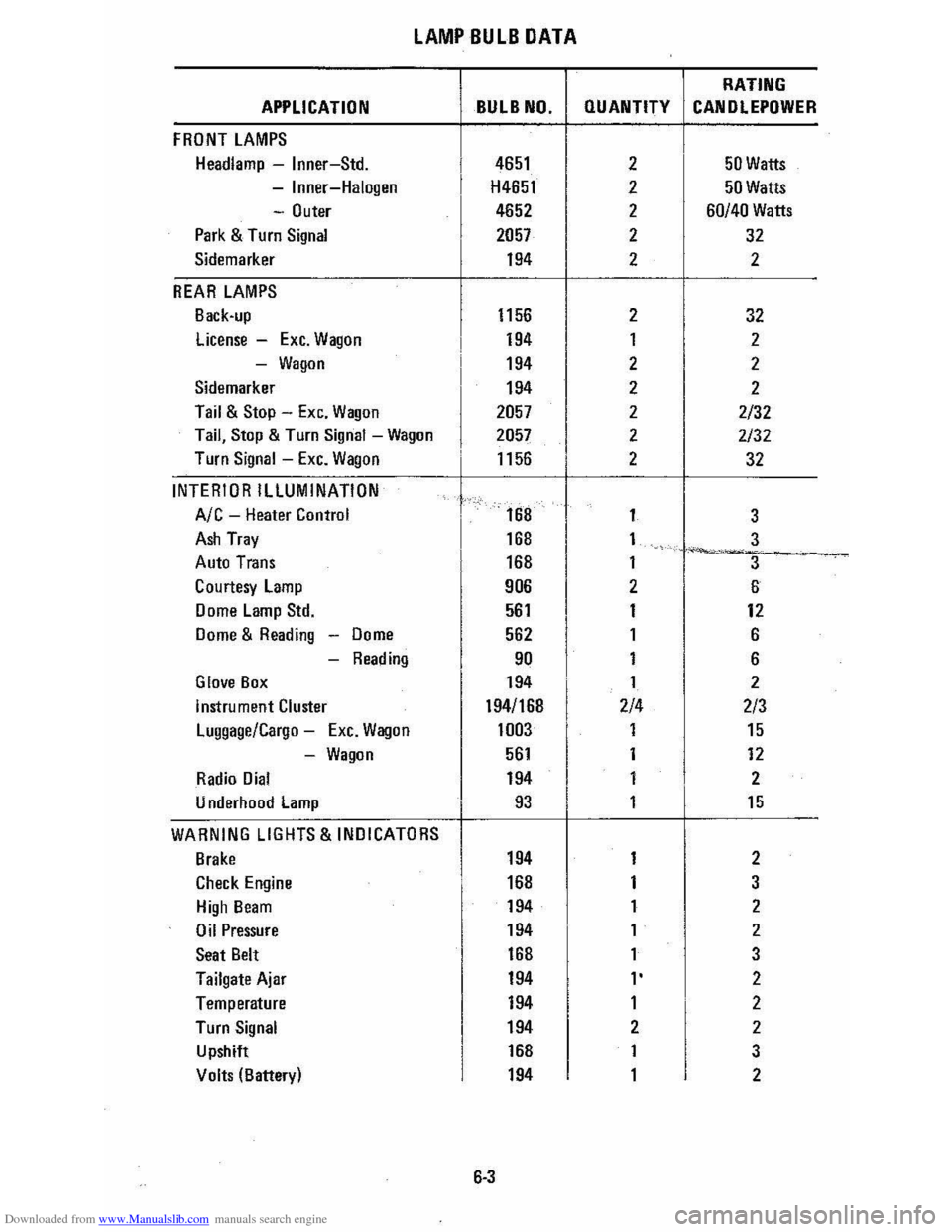
Downloaded from www.Manualslib.com manuals search engine LAMP BULB DATA
RATING
APPLICATION BULB NO. QUANTITY CANOLEPOWER
FRONT LAMPS
Headlamp -Inner-Std. 4651 2 50 Watts
-Inner-Halogen H4651 2 50 Watts
-Outer 4652 2 60/40 Watts
Park & Turn Signal 2057 2 32
Sidemarker 194 2 2
REAR LAMPS
Back-up 1156 2 32
license -Exc. Wagon 194 1 2
-Wagon 194 2 2
Sidemarker 194 2 2
Tail & Stop -Exc. Wagon 2057 2 2/32
Tail, Stop & Turn Signal -Wagon 2057 2 2/32
Turn Signal -Exc. Wagon 1156 . 2 32
INTERIOR ILLUMINATION
Ale -Heater Control
I
168 1
3
Ash Tray 168 1 3 ~-..... -Auto Trans 168 1
3
Courtesy lamp 906
I
2 6
Dome Lamp Std. 561 1 12
Dome & Reading -Dome 562
I
1 6
-Reading 90 1 6
Glove Box 194 1 2
instrument Cluster 194/168 2/4 2/3
Luggage/Cargo -Exc. Wagon 1003
I
1 15
-Wagon 561 1 12
Radio Dial 194 1 2
U nderhood lamp 93 1 15
WARNING LIGHTS & INDICATORS
Brake 194 1 2
Check Engine 168 1 3
High Beam 194 1 2
Oil Pressure 194
I
1 2
Seat Belt 168 1 3
Tailgate Ajar 194 l' 2
Temperature 194 1 2
Turn Signal 194 2 2
Upshift
I
168 1 3
Volts (Batter) 194 1 2 y
6·3
Page 100 of 105
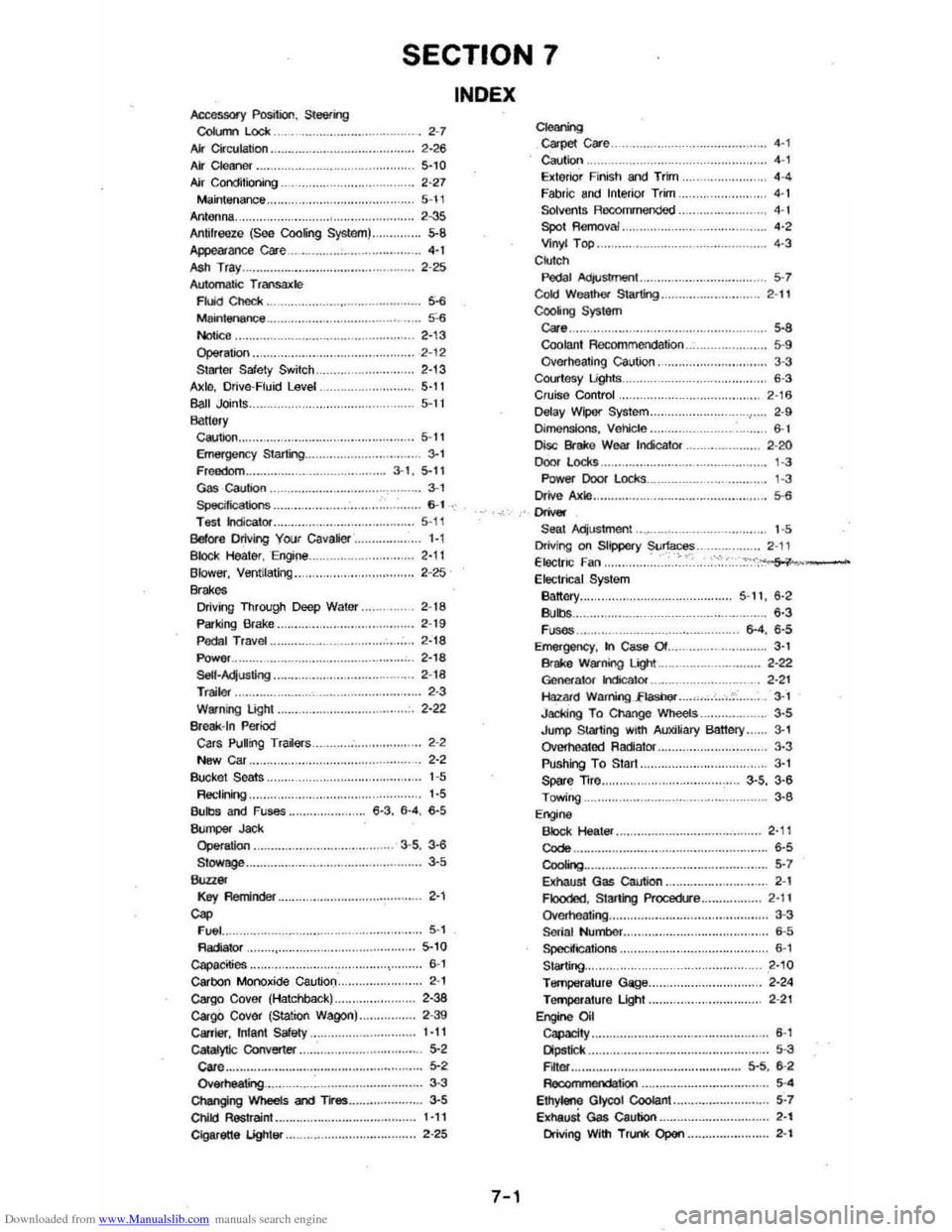
Downloaded from www.Manualslib.com manuals search engine SECTION 7
Accessory Position, Steering CoIl.m Lock 2-7 AIr Cir ctJlalioo. . 2-26 Ai' Cleaner. 5-,0 Air Conditio ning ............ . 2-27 M ainte nance .. Antenna . 5-\1 2 -35 5-8 Antifreeze (See Coo~ng System) .. Appearance cae ...• ....•.. 4·t .... ...... 2 -25 ASh Tra y .. Automatic T 'ansalC!e Fluid Chedi: . ___ .. . _ ..... _ ._ ... ... . Maintenance .. Notice ,. .. Op$ralion .. Surter Safety Switch Axlo, Drive-Fluid Level Ball Joints. Ba"&,y
· ....... 5-6 .... 5'-6 2,13 · .... 2 -12 2'13
........ . 5-11 5-1 I
Caution.. 5-11 Emergenc y Starling.. 3-1 Freedom.. .. 3·1 , 5-11 Gas caution . ___ ............. ..... ... . ...... .... 3·, Specilicalions .... ... ... ... .. ... .. .. . T esl indlealor .. Belor e Driving Your cavalier .. B loc k Healer, Engine Blower, Ventilating .. Brakes Driving Through Deep Water "
Parking Brake .. P eda l TraVel .. Power ... SelI·AqusIing ...... ... ..... .. ... .. .. . T railer ..... . Warning Light .. Br eak -In Period Cars Pulrng Tra~ars New Car .. Bucke l Seats .. R ttelininQ .. Bulbs and Fuses ..
""_ Jad< Operation . Stowage ............. ... ... .. .... •..•. • _ ..
Key RemiAder .. Cap FIJI:II .. R adiator Capa.cities .. carbon Monoxide Caution .. Cargo Cover (Hatchback) .. cargO Cover (Station Wagon) ... Carrier, Infant Safety .. cataIytlc Converter .. care .... OwNheatng ....... . Changing Wheels and Tl"es .. Ct\IICI Restraint.. Cigarette lightsr ..
. .... 6 -1 . . . 5-1 1 1-1 2-11 2-25
2 -18
2 -19
2·18 •.••.•. 2, 18 2-1 8 ....... ... .. 2· 3 2·22
2-2
2-2
1 -5
1-5
6 ·3. 6·4 . 6-5
3 ·5 . 3-6 ........ . 3-5
· ....... 2·'
5 -1 5-10 .... .. 6-1 2 -1 2-38 2 -39 1·11 5-2 ...... .... 5-2 ..3 -3 ....•.••. . 3·5 1-11 · ..... 2-25
INDEX
7-1
C1eri'9 c;a.pet care .. Caution .. Exteriof Finish and Trim Fabri c and Interio r Trim .. Solvents Racomme nded Spot Removal. Vinyl Top .. C kl tch
. .... 4·' . ..... 4 -' 4 -' 4 -1
4 -1
..,
4-3
PeDa l Acl/Ustmeot ........ ... ... ... .......... ........ 5·7 Cold Wealhet Starting ... ... ... ...... ... ... ...... 2·11 CooIiIl9 System care. .. . 5 ·8 Coolan t Rocommeodation 5-9 Overhea ting caution. 3-3 Courtosy Lights .. 6-3 Cruis e Con trof 2-16 Defay Wipo( Sys tem ....................... ,.. 2 -9 [)jmensions, Ve)jcle.. . ......... 6-1 [Xsc Brake Wear IrKicator .......... 2-20 Door locks ' -3 Power Door l ocks ... Drive Axle
"""" Seal Adjus tment. .. Driving on Slippery Surfaces Electn c Fan .. Electric al System Battory .. Bulbs .• . . FI.ISOS ..•..• Emergency. In Case Of . Brake W~ning Liglt .. 1
-3
.• 5·6
1 -5 2 -\' .... ~::<',~~-
5 '11, 6·2 '·3 6-4. 6·5 . .... ..... .. 3 · . ... 2 ·22 Geoefator hdicalor... . ...... 2 ·2 1 Hazru"d Warring . .,fLashef ... -'. __ .... ,,, 3 ·1 Jaddng T o Change Wheels 3·5 Jump Starling with Auxi~ary Banel)'. . 3· Overhe.1tod Radiator.. 3·3 Pushing To Start.. 3-I Spar e Trre.. . . .................... 3-5 , 3·6 Towing.. 3·6 Engine Block Heater ... Codo .. CooIO>g •••.
2 ·' , . . .. . 6·5
5 ·7
8I:haust Gas Caution ............... ... ... ... ... 2-1 Flooded, Staring Procedlre ................ 2·11 Qvome ating ................... ....... .... ............. . 3-3 Serial NulTlbef.. . .... 6-5 Specifications . ............... . ..... . .. ..... .......... 6-' Starting... 2·10 Temperature Gage.. 2 ·24 TefTlP(Iralure Light. 2 -21 EnginO Oil Capacity .. Dipstick •• F~Of . . .
. ............ ....... ... .. .... .......... ... 6-1
Reoo .. wnonootion .. Ethyteno Glycol Coolant .• EXhaUst Gas Caution . .
• •••• 5 -3 5·5. 6 ·2
5 ·'
5 ·7 . ....... 2·' Driving With Trunk Open ..... .. ............. . 2-'