heating CHEVROLET CAVALIER 1984 1.G Owners Manual
[x] Cancel search | Manufacturer: CHEVROLET, Model Year: 1984, Model line: CAVALIER, Model: CHEVROLET CAVALIER 1984 1.GPages: 105, PDF Size: 24.23 MB
Page 17 of 105
Downloaded from www.Manualslib.com manuals search engine SECTION 2
STARTING AND OPERATING
ENGINE EXHAUST GAS CAUTION
(CARBON MONOXIDE)
CAUTION:-Do not breathe exhaust gas because it contains carbon monoxide, which by itself has no color crador. Carbon monoxide is a
dangerous gas. It can cause unconsciousness and can be lethal.
If at any time you think exhaust fumes are entering the vehicle, have the cause
determined and corrected as soon as possible. If you must drive under these conditions, drive only with ALL windows lully OPEN.
Protect against carbon monoxide entry into the vehicle body. The best way is
to keep the engine exhaust system,
vehicle body and body ventilation system
properly maintained. We recommend that the exhaust system and body be
inspected by a competent technician:
• each time the vehicle is raised for an oil change;
• whenever a change is noticed in the sound, of the exhaust system;
• whenever the exhaust system, underbody or rear of the vehicle is damaged
or becomes corroded.
See your Maintenance Schedule folder for parts requiring inspection.
To allow proper operation of your vehicle's ventilation system, keep the air inlet
grille in front of the windshield clear of snow, leaves or other obstructions at all
times.
DO NOT PARK WITH THE ENGINE RUNNING OR IDLE THIS VEHICLE FOR
MORE
THAN 10 MINUTES WITH THE VENTILATION SYSTEM CONTROL
SWITCH
IN THE "OFF" POSITION. EVEN WITH THE VENTILATION SYSTEM ON, RUNNING THE ENGINE WHILE PARKED OR STOPPED FOR LONGER
PERIODS OF TIME IS NOT
RECOMMENDED. ENTRY OF CARBON
MONOXIDE INTO THE CAR BODY IS POSSiBlE WITH A POORLY REPAIRED, DAMAGED, OR CORRODED EXHAUST SYSTEM OR BODY.
Do not run the engine in CONFINED areas (such as garages or next to a
building) any more than needed to move the vehicle. When the
vehicle has to
be stopped
in an UNCONFINED area with the engine running for any more
than a few minutes, take the following steps:
A. Adjust the heating or cooling system to force outside air into the vehicle as
follows:
1. On vehicles not equipped with air conditioning, set the fan to
intermediate or high speed and the upper control lever to any position.
2. On vehicles equipped with air conditioning, set the fan to an
intermediate or high speed and the upper control lever to any position
except
"OFF" or "MAX."
B. Keep the exhaust tailpipe area clear of snow and other material to help
reduce the buildup of exhaust gases under the vehicle. This is particularly
important when parked in blizzard conditions.
2-1
Page 18 of 105
Downloaded from www.Manualslib.com manuals search engine Driving with the trunk lid, hatchback or liftgate on station wagon models open is not recommended. Under some conditions, exhaust gases may be drawn
into the vehicle. If the trunk lid, hatchback or liftback must remain open for
some reason while moving, or if electrical wiring or other cable connections to a trailer must pass through the seal between the trunk lid, hatchback or liftback
and the body, follow these precautions:
• Close all windows.
• Adjust the heating or cooling system to force outside air into the vehicle as
described abcve, but set the fan to high speed.
• On vehicles with outside air vents in or under the instrument panel, open the vents fully.
NEW VEHICLE "BREAK-IN" PERIOD
You can drive your new vehicle from its very first mile/kilometer without
following a formal "break-in" schedule. However, there are things you can do during the first few hundred miles/kilometers of driving that will add to the
future performance and economy of your vehicle.
We recommend you limit your speed during the first 500 miles (800 kilometers)
to a maximum of 55 mph (90 km/h); but do not drive for long periods at any
one constant speed, either fast or slow. During this time, avoid full throttle
starts and, if possible, avoid hard stops especially during the first 200 miles (320 kilometers) of driving.
Always drive at moderate speed until the engine has completely warmed up.
I! you plan to use your new vehicle for trailer towing, see the following.
TRAILER TOWING
This car is designed and intended to be used mainly to carry people. Towing a
trailer
will affect handling, durability and economy. Your safety and satisfaction
depend upon proper use of correct equipment. Also, you should avoid
overloads and other abusive use.
The maximum loaded trailer weight you can pull with your vehicle depends on
your intended use
and what special equipment has been installed on it.
Information on trailer towing ability, special equipment required, and optional
equipment available should be obtained from your dealer. Ask for the trailering brochure. Or, write: Consumer Relations Department, Chevrolet Motor
Division, Warren, Michigan 48090.
(In Canada, write to General Motors of
Canada Limited, Customer Services Department, Oshawa, Ontario L lJ 5Z6.)
Tires
When towing trailers, be sure your tires are properly inflated to the inflation pressure shown on the Tire Placard on the driver's door.
The allowable passenger and cargo load for this vehicle, also shown on the
Tire
Placard, is reduced by the trailer tongue weight whenever the trailer is
attached to the vehicle. See "Service and Maintenance," Section 5 for more tire information.
Maintenance
More frequent service is required when using your vehicle to pull a trailer. See
the Maintenance Schedule folder for Automatic Transaxle Fluid and Engine Oil change requirements for trailering.
2-2
Page 20 of 105
Downloaded from www.Manualslib.com manuals search engine NonCE: Use only trailer hitches which permit normal operation of the Energy
Absorbing Bumper system, If so equipped. For example, a rigid fore and aft connection between the bumper and any other part of-the vehicle may increase damage in the event of a collision.
TRAILER TOWING TIPS
Getting Started
Before entering traffic with a trailer that has electric brakes, start the vehicle and trailer moving and apply the trailer brakes by hand to be sure the trailer
brakes are working and the trailer electrical system is connected.
Engine Cooling
If your engine overheats, follow the steps under "Engine Cooling System
Overheating" in "In Case of Emergency," Section 3 of this manual.
Long Uphill Grades
When going up long grades, you can reduce the chance 01 engine overheating
by turning off the air conditioner, if so equipped.
Down Steep Or Long Grades
Before going down a steep or long grade, reduce speed and shift the transaxle
into a lower gear to help control your vehicle's speed. Try not to hold the brake pedal down too long or too often. This could cause the brakes to overheat and
reduce brake effectiveness.
Transaxle
See the method for checking the transaxle fluid level in "Service and
Maintenance,"
Section 5 of this manual.
Parkin!!
You should not park vehicles with trailers on a grade (hill). However, if you
must park on a grade, these steps must be followed:
1. Apply the regular brakes.
2. Have someone place wheel chocks under the trailer wheels.
3. When the wheel chocks are in place, release the regular brakes until the
chocks absorb the load.
4. Apply the parking brake.
5. Shift the transaxle to "P"(Park),
If the vehicle is parked on a grade, don't shift the transaxle to "P"(Park) until the trailer wheels are chocked and the parking brake is set. If you do, the
weight of the
vehicle and trailer may put so much force on the parking pawl in
the transaxle that it may be hard to shift out of "P"(Park).
When starting, after being parked
on a grade:
1. Apply the regular brakes and hold.
2. Start the engine in "P"(Park).
3. Shift into gear and release the parking brake.
4. Release the regular brakes and drive until the chocks are free.
5. Apply the regular brakes and have someone remove the chocks.
2·4
Page 24 of 105
Downloaded from www.Manualslib.com manuals search engine CAunOM: tf you need to tum oft the ... whikt the vehicte ls moving, turn the key only to "Oft." DO NOT depreSS the key release lever while turning the Ignition off._This
wln ·lock the steering column and result in loss arability to steer the vehlete.
If you have trouble turning the key to unlock the ignition, first be sure the key is
pushed in all the way . Then , try to turn the steering wheel as hard as you can .
in the direclioo the
wheels are tUrned . At the same ti me , turn the ignition kay
w~h as much eftort as you can apply with your hand. Do not try to use a tool of
any kind to
apply more force on the lock knob , as tnis could break the knob.
NOTICE: Do not park, idle, or operate your vehk:le over combustible materials, such
as grass or leaves . They couki touch the hot exhaust ay8tem and ignite.
Parking
CAUTION: Before the driver leaves this vehicle, to reduce the risk of personal injury ... resun of vehicle movement:
1. Firmly apply the parking brake.
2. Shift the automatic transtixle to Park or the manual tranSlale to "Reverse."
3. Tum the kef to "Lock. " On vehietn wrth manual transaxle$, __ ~ the key reiease tever and tum the key to·'Loclic. " .
4. Remove the key (the chime ia designed to remind you).
To reduce the chance of persona' injury and/or vehicle damage due' to engine overheating , never lellVe the engine Idling without an alert driver present. If the engine ahoukl overheat, as indicated by the Erlgine Coolant Temperature light Of gage,
Immediate action 1a required to correct the concIUon. Continued operation 01' the engine . enn FOA -A SHORT TtME may resutt In a fire.
TURN SIGNAL AND MULTI-FUNCTION LEVER
The turn signal lever on the left side of the steering column also controls headlight low-beam and high-beam, the windshield wiper/washer, and the
optional Cruise
Control. (See Cruise Control operatiOn in this section .)
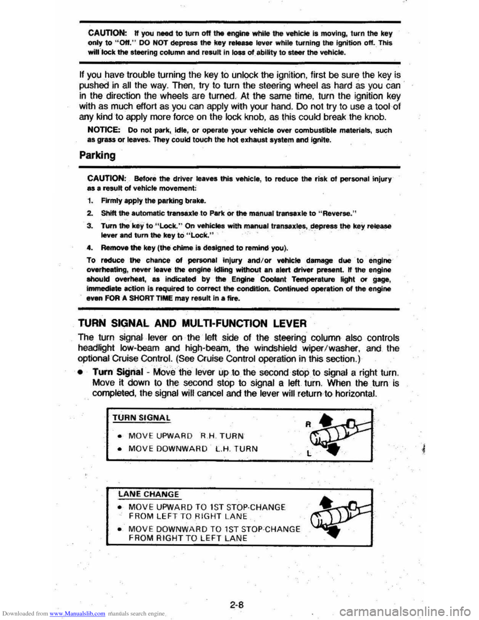
• TUI'fI Si!Jnal -MOve the lever up .to the second stop to signal a right turn.
Move
~ down to the second stop to signal a left turn. When the turn is
completed, the signal will cancel and the lever will return to horizontal.
TURN SIGNAL
• MOVE UPWARD R.H . TURN
• MOVE DOWNWARD L.H. TURN
LANE CHANGE
• MOVE UPWARD TO 1S T STOP·CHANGE
FROM LEFT TO RIGHT LANE
• MOVE DOWNWARD TO 1ST STOP ·CHANGE FROM RIGHT TO LEFT LAN E
2-8
Page 35 of 105
Downloaded from www.Manualslib.com manuals search engine PARKING BRAKE
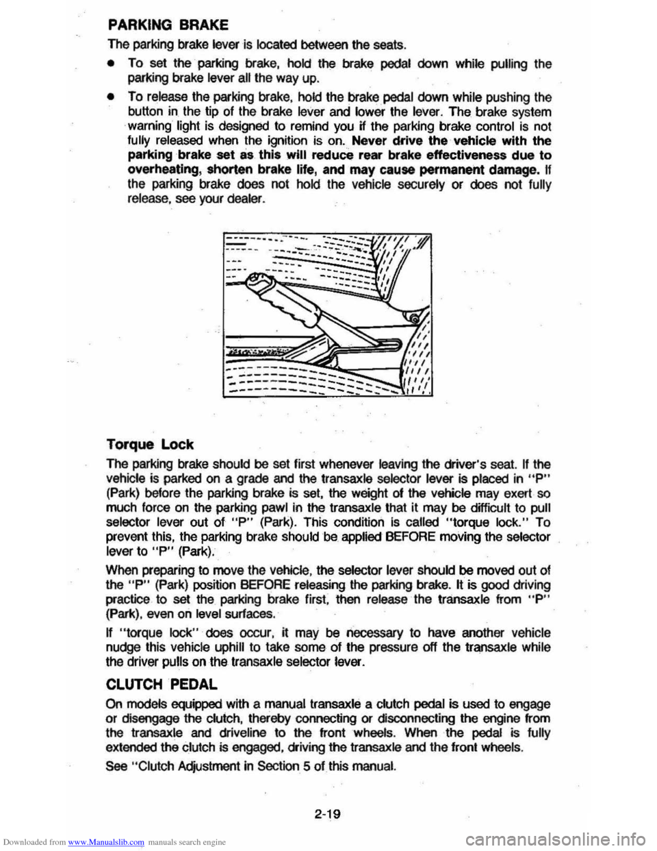
The parking brake lever is located between the seats .
• To set the parking brake, hold the brake pedal down while pulling the
parking brake
lever all the way up.
• To release the parking brake, hold the brake pedal down while pushing the
button in the tip of the brake
lever and lower the lever. The brake system
warning light is designed to remind you H the parking brake control is not fully released when the ignition is on. Never drive the vehicle with the
parking brake set as this will reduce rear brake effectiveness due to
overheating, shorten brake life, and may cause permanent damege, If
the parking brake does not hold the vehicle securely or does not fully release , see your dealer .
Torque Lock
The perking brake should be set first whenever leaving the driver's seat. If the vehicle is parked on a grade and the transaxle selector lever is placed in "P"
(Park) before the parking brake is set, the weight 01 the vehicle may exert so
much force on the parking pawl in the transaxle that it may be difficult to pull
selector lever out of "P" (Park). This condition Is called "torque lock." To
prevent this, the parking brake should be applied BEFORE moving the selector lever to "P" (Park).
When preparing to move the
Vehicle , the selector lever should be moved out of the "P" (Park) position BEFORE releasing the parking brake. It is good driving
practice to
set the parking brake first. then release the transaxle from "P" (Park), even on level surfaces .
n "torque lock" does oocur, it may be necessary to have another vehicle
nudge this vehicle uphill to take some of the pressure off the transaxle while
the driver pulls on the transaxle selector lever.
CLUTCH PEDAL
On models equipped with a manual transaxle a clutch pedal is used to engage
or disengage the clutch, thereby connecting or disconnecting the engine from
the transaxle and dliveline to the front wheels . When the pedal is fully
extended the clutch is engaged, driving the transaxle and the front wheels .
See "Clutch Adjustment in Section 5 of this manual.
2·19
Page 37 of 105
Downloaded from www.Manualslib.com manuals search engine • Amount of fuel required for fill-up may not exactly correspond to gage.
• Needle may not move away from FULL until some time after fill-up.
• Needle may move during turns; stops and accelerations.
When the ignition switch is turned to the OFF position, the needle will not
necessarily return
all the way to the EMPTY mark.
Oil Pressure Light
When the ignition is turned to "Run," the "Oil" warning light appears until the
engine is started. Thereafter, the light should be off unless there is insufficient
oil pressure or engine idle speed is below normal. If the light should come on
at any time while driving (other than momentarily at idle speed or after a
sudden stop), stop immediately and investigate the cause of
low oil pressure.
This could possibly be caused by low oil level in the crankcase. Engine
operation with low oil pressure will 9ause damage to the engine.
Engine Coolant Temperature Light
This light is located in the instrument cluster and is designed to come on to warn the driver that the engine coolant has overheated and immediate
action is required to correct the condition. As a check that the bulb and its
circuit are working, the light will come on during engine starting; if it does not,
have it repaired
promptly. If the light comes on at any other time, see "Engine
Cooling System Overheating" in "In Case of Emergency," Section 3 of this manual.
CAUTION: It the Engine Coolant Temperature Light shows an overheat condition or you have other reason to suspect the engine may be overheating, continued operation of the engine EVEN FOR A SHORT TIME may result in a fire and the risk of personal injury and/or severe vehicle damage. Take immediate action as outlined under "Engine Cooling System Overheating" in "In Case of Emergency," Section 3.
Generator Indicator Light
The VOLT light is designed to come on when the ignition key is in the "RUN" position, but before the engine is started. After the engine starts, the light
should go out and remain out. If the light remains· on when engine is running,
have your authorized
dealer locate and correct the trouble as soon as possible.
Shift Indicator Light
The Shift Indicator Light is covered in the "Manual Transaxle" information in
this section.
"Check Engine" Light
Most gasoline engine vehicles sold in the Unijed States (and some vehicles
sold
in Canada) have the Computer Command Control system.
Vehicles with the Computer Command Control system include a "CHECK
ENGINE" light
on the instrument panel designed to indicate the need for
system service. It will come on during engine starting to let you know the bulb
is working. (The light will stay on a short time after the engine starts.)
2-21
Page 40 of 105
Downloaded from www.Manualslib.com manuals search engine Engine Coolant Temperature Gage
This optional gage is located in the instrument cluster. If the gage shows that
an overheat condition exists-as indicated by pointer moving beyond the
center of the band immediate action by the driver is required. If an overheat
condition is shown, see "Engine
Cooling System Overheating" in "In Case of
Emergency,"
Section 3 of this manual. The coolant temperature indication will VaIY with air temperature and operating conditions. The ignition must be in
"Run" for accurate readings. Prolonged driving or idling in very hot weather
may cause the pointer to move beyond the center of the gage. Make a practice
of scanning this and other gages
while driving, especially in hot weather and!
or when the
vehicle is under load.
CAUTION: II the Engine Coolant Temperature Gage shows an overheat condition or you have other reason to suspect the engine may be overheating, continued operation of the engine EVEN FOR A SHORT TIME may result in a fire and the risk of personal injury and/or severe vehicle damage. Take immediate action as outlined under "Engine Cooling System Overheating" in "In Case of Emergency," Section 3.
Oil Pressure Gage
The oil pressure gage indicates the pressure at which oil is being delivered to
the vaIiOUS paIls of the engine requiring lubrication. Pressures registered by
the gage may
vBIY according to outside air temperatures or weight of oil being
used. Oil pressure of a cold engine being operated at a given speed will be
somewhat higher than when the engine is at normal operating temperature at
the
SaIne speed. Prolonged high speed operation on a hot day at the given
speed will
resuH in somewhatlower oil pressure readings. Readings of 205 to
275 kPa
(30 to 40 psi) may be considered normal during moderate road
speeds of 35 to 40 mph (55 to 60 km!h) with the engine at proper operating
temperature. Gage readings which are consistently high
or low under these conditions may indicate lubrication system and/ or engine malfunction.
Light Switch
The three· position light switch controls the headlights, taillights, paIking lights,
sidemaIker lights,
instrument lights and dome lights.
Instrument light intensity can be varied by turning knob clockwise or
counterclockwise. Full counterclockwise position turns on interior light.
The headlight circuit is protected by a circuit breaker in the
light switch. An overload on the breaker will cause the lights to "flicker" on and off. If this
condition
develops, have your headlight wiring checked immediately. The
headlight beaIn changer is located in the Turn Signal Lever; for operation see
Section 2 under heading "Turn Signal and Muiji-Function Lever."·
Headlight High Beam Indicator Light
The headlights of your vehicle have. high and low beams to provide you with
proper nighttime visibility for most driving conditions. The
"low" beams are
used during most city driving. The
"high" beams are especially useful when
driving on daIk roads since they provide long range illumination. The headlight
beam indicator light (located on the speedometer face) will be ON whenever
the high beams or "brights" are in use. The turn
signal lever controls the
headlight beaIns and is described in "Steering Column Controls."
2-24
Page 41 of 105
Downloaded from www.Manualslib.com manuals search engine Headlight "ON" Warning Buzzer/Chime
The optional headlight reminder buzzer/chime provides an audible warning that the main light switch is in one 01 the "on" positions , either parking lights
or headlights.
The reminder buzzer/chime is activated only when the ignition switch is turned to "OFF," "LOCK" or "ACCESSORY" position and the lights are on.
When the parking lights
or headlights are to be operated with the key in the
OFF position, the reminder buzzer/chime can be shut off by turning the light
switch knob until the instrument cluster lights are not on,
CIgarette Ughter (Optional)
The cigarette lighter is located on the instrument pane! face. To operate, push
~ in. When ~ becomes heated, ~ automatically pops out ready for use. Avoid
holding the lighter in by hand while ~ is heating as damage to the heating
element may result.
Ashtray
The ashtray may be simply pulled out for cleaning:
• Open ashtray.
• Pull ashtray up and remove for cleaning .
•
Push ashtray back into bracket.
VENTILATION SYSTEM
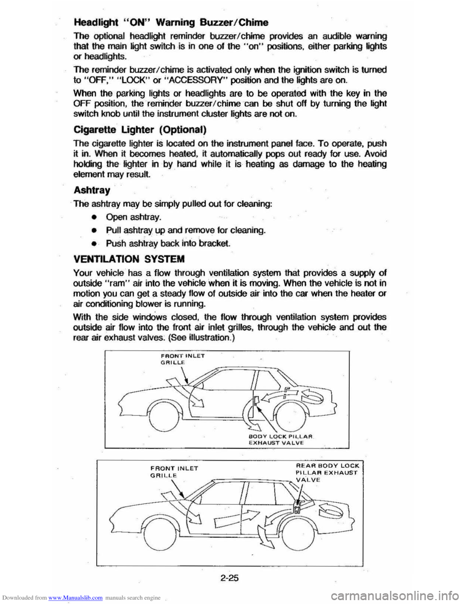
Your vehicle has a flow through ventilation system that provides a supply of outside "ram" air into the vehicle ' when it is moving . When the vehicle is not in
motion you can get a steady flow of outside air into the car when the heater or
air conditioning blower is running.
With the side
windOws closed, the flow lIYough ventilation system provides
outside air flow into the front air inlet grilles, through the vehicle and out the
rear air exhaust valves. (See illustration .)
FRONT INLET
2-25
REAR BODY LOCK PILLAR EXHAUST
Page 43 of 105
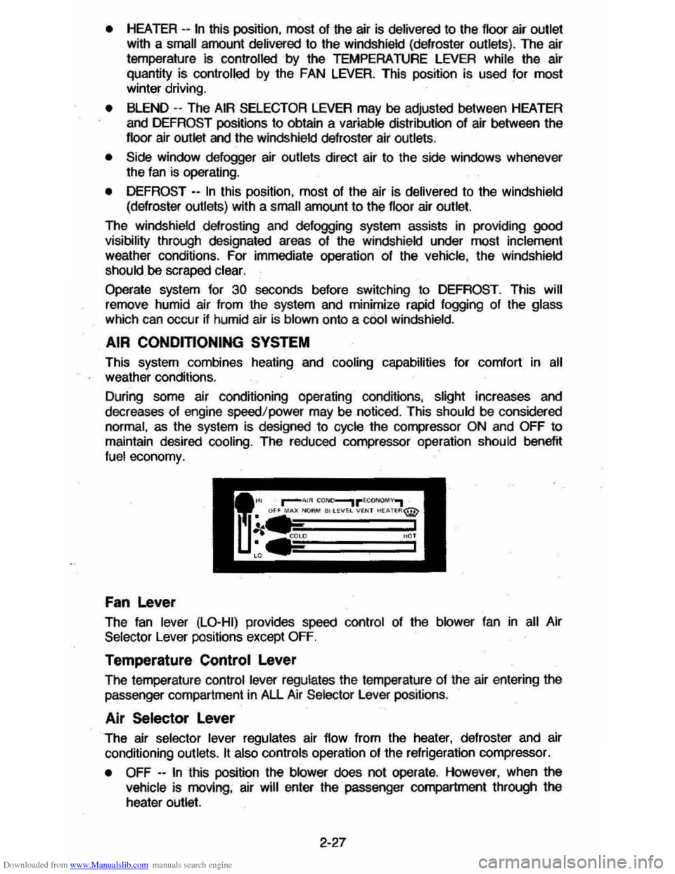
Downloaded from www.Manualslib.com manuals search engine • HEATER --In this position, most of the air is delivered to the floor air outlet
with a small amount delivered to the windshield (defroster outlets). The air
temperature
Is controlled by the TEMPERATURE LEVER while the air
quantity
is controlled by the FAN LEVER. This position is used for most winter driving.
• BLEND -- The AIR SELECTOR LEVER may be adjusted between HEATER
and DEFROST positions to obtain a variable distribution of air between the
floor air outlet and the windsh ield defroster air outlets.
• Side window defogger air outlets direct air to the side windows whenever
the fan is operating.
•
DEFROST - -In this poSition, most of the air is delivered to the windshield
(defroster outlets) with a small amount
to the floor air outlet.
The windshield defrosting and defogging system assists in providing
good visibility through designated areas of the windshield under most inclement
weather conditions . For immediate operation of the vehicle, the windshield
should be scraped clear.
Operate system for 30 seconds before switching to DEFROST . This will
remove humid air from the system
and minimize rapid fogging of the glass
which can occur if humid air Is blown onto a cOol windshield .
AIR CONOmONING SYSTEM
This system combines heating and cOOling capabilities for comfort in all weather conditions.
During some air conditioning operating conditions, slight increases and
decreases of engine speed/power may be noticed . This
should be considered
normal, as the system is designed to cycle the compressor
ON and OFF to
maintain desired cooling. The reduced compressor operation should
benef~ fuel economy.
Fan Lever
The fan lever (LO-HI) provides speed control of the blower fan in all Air
Selector Lever positions except
OFF.
Temperature Control Lever
The femperature control lever regulates the temperature of the air entering the passenger compartment in All Air Selector Lever positions .
Air Selector Lever
The air selector lever regulates air flow from the heater, defroster and air
conditioning outlets.
It also controls operation of the refrigeration compressor.
•
OFF --In this position the blower does not operate . However, when the
vehicle is moving, air will enter the· passenger compartment through the
heater outlet.
2-27
Page 44 of 105
Downloaded from www.Manualslib.com manuals search engine • MAX (AIR COND) --Air from the passengel' cOlTlpaftment is mixed with a small amount of outside air. conditioned and discharged from !he upper
outlets . This position. with the temperature
lever in full COLD. is used for
maximum cooling under conditions of high temperature and humidity .
• NORM (AIR COND) --Outside air is conditioned as ~ passes through the
system and is discharged from the upper outlets. This position is used for most air conditioning situations.
• BI-LEVEL (AIR COND) --Outside air is conditioned and directed out the
upper outlets PLUS the heater outlet. This position provides comfort and
keeps the windshield clear under low fogging conditions .
• VENT (ECONOMY) --Outside air is discharged from the upper outlet s. This position is provided for cool to moderate weather operation when
refrigeration is not required. The refrigeration compressor is turned off.
Operating Information -The engine cooling fan is automatically engaged in all air conditioning modes and defrost mode (with high air conditioning pressure).
• HEATER (ECONOMY) --Outside air is delivered from the heater outlet with
a small amount from the defroster outlets and the side window . defogger outlets. This position is used for most winter driving. The air conditioning compressor is turned off.
• DEFROST c_ Outs ide air is cond~ioned and delivered from the defroster
outlets w i1h a small amount from the heater outlet. This position is
recommended for conditions of severe fogging and icing
only.
Operating Tip
For satisfactory operation of the air conditioning system. windows should always be closed, except for the first two or three minutes to remove hot air if
the car has been closed. This provides a fast cool-down in normal air
conditioning mode.
ELECTRO-CLEAR REAR WINDOW DEFOGGER
The optional defogger consists of a heating element bonded to the inside
surface
of the rear glass . The unit is operated by a switch on the instrument panel and functions only in the ON position. When activated an indicator light
will illuminate.
After the defogger has operated for a short time. the system will
automatically shut off. If further defrosting or defogging is desired . simply actuate the switch again.
The defogger
will not function if the ignition is turned off.
Refrain from removing decals or other materjal' from the inside of rear window
with a razor or other sharp instrument since this may damage . the heating
element.
Clear snow and ice from the rear window to improve tihe efficiency of the rear
window defogger.
2-28