heater CHEVROLET CAVALIER 1984 1.G Owners Manual
[x] Cancel search | Manufacturer: CHEVROLET, Model Year: 1984, Model line: CAVALIER, Model: CHEVROLET CAVALIER 1984 1.GPages: 105, PDF Size: 24.23 MB
Page 27 of 105
Downloaded from www.Manualslib.com manuals search engine 4. Apply the regular brakes and shift into the proper gear. Release the
parking brake and drive oft.
IF ENGINE FAILS TO START AFTER NORMAL STARTING
PROCEDURE
1. If you tried the Cold or Warm Engine starting procedure and the engine still
does not start, push down the accelerator pedal to the floor and hold it
there while cranking the engine. This should clear the engine
~ II is flooded.
2. If the engine has been flooded with too much fuel, it may start to run but
not have enough power to keep running .
In that case, continue cranking
with the
accelerator pedal all the way to the floor until the engine clears itseW of excess gasoline and runs smoothly . (But, do not crank more than
15 seconds at a time or you could damage the starter .)
GaSOline Engine Block Heater
The optional gasoline engine block heater is designed to warm the block area
for improved cold weather starting.
II can also help reduce fuel consumption
when a cold engine is warming up.
To use
the block heater:
1 . Open the
hood. '~".
2. Unwrap the electrical cord which is stowed In the engine compartment.
(After using the block heater, be SUre to properly restow the cord , to help
keep it away from moving engine parts.)
3. Plug the cord into any three-prong, 11 O-voll outlet (normal household
current).
NOTICE: • the cord i, too ahort, use a ~avy·duty, three-prong extension corel Do not use an extension cord such .. you would uae for • t.np because the cord rnIIY
--Outside temperature, oil viscosity, etc. will affect how tong the block~ heater should remain plugged .in . Contact your authorized dealer for advice 'jot the
conditions in your area.
TRANSAXLE
DESCENDING A GRADE
CAunON: To reduce the risk of personaJ injUry. before going down 8 .steep or long Wade reduce speed and shift the transaxte -into second or low gear to help control your speed. (00 this with EITHER an automatic or manual transax)e.) Do not hold the brake ~I down too Iorig or too otten white going down • steep or long grade. This COUld ceu" the brakes to get hot and not work as well. As • result, the vehicle will not slow down at the usual r.t.~ Failure to u.ke these steps could r8l,,1t in. Iou of vehicle control.
DRIVING ON. SUPPERY SURFACES
While driving on a slippery surface avoid sudden acceleration, or engine
braking actions (due to shifting to a lower gear), which could cause the wheels
to skid . Skid correction is called for at these times.
2-11
Page 39 of 105
Downloaded from www.Manualslib.com manuals search engine '" ,
t:l
STANDARD INSTRUMENT CLUSTER
IJ
12
OPTIONAL INSTRUMENT CLUSTER
~~~~-:'----,~~:
l'l
1l
10
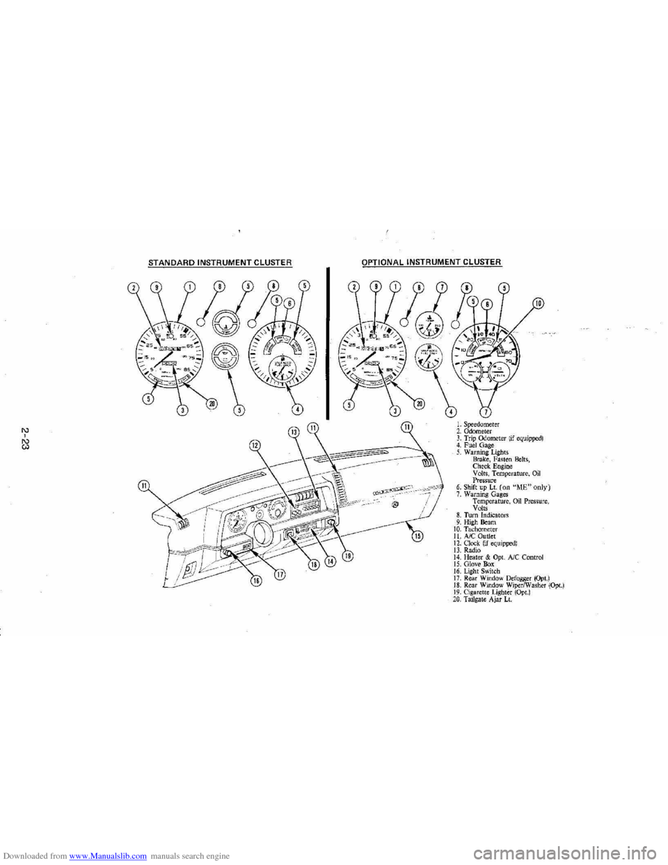
L Speedometer 2. Odometer 3. Trip ()jometer lif equipped) 4. Fuel Gage 5. Warning Lights Brake, Fasten Belts, Check. Engine Volts, Temperature, Oil Pressure 6. Shift up Lt. (on "ME"only) 7. Warning Gages Temperature, on Pressure, Volts 8. Turn Indicators 9. High Beam 10. Tachomet er 11. A/C Outlet 12. Clock. (if equipped) 13. Radio 14. Heater & Opt. Ale Control 15. Glove Box 16. Lig ht Switch 17. Rear Window Defogger (Opt.) 18. Rear Window WiperlWasher (Opt.) 19. Cigare tt e Lighter (Opt.) 20, Tailgat e Ajar Lt.
Page 41 of 105
Downloaded from www.Manualslib.com manuals search engine Headlight "ON" Warning Buzzer/Chime
The optional headlight reminder buzzer/chime provides an audible warning that the main light switch is in one 01 the "on" positions , either parking lights
or headlights.
The reminder buzzer/chime is activated only when the ignition switch is turned to "OFF," "LOCK" or "ACCESSORY" position and the lights are on.
When the parking lights
or headlights are to be operated with the key in the
OFF position, the reminder buzzer/chime can be shut off by turning the light
switch knob until the instrument cluster lights are not on,
CIgarette Ughter (Optional)
The cigarette lighter is located on the instrument pane! face. To operate, push
~ in. When ~ becomes heated, ~ automatically pops out ready for use. Avoid
holding the lighter in by hand while ~ is heating as damage to the heating
element may result.
Ashtray
The ashtray may be simply pulled out for cleaning:
• Open ashtray.
• Pull ashtray up and remove for cleaning .
•
Push ashtray back into bracket.
VENTILATION SYSTEM
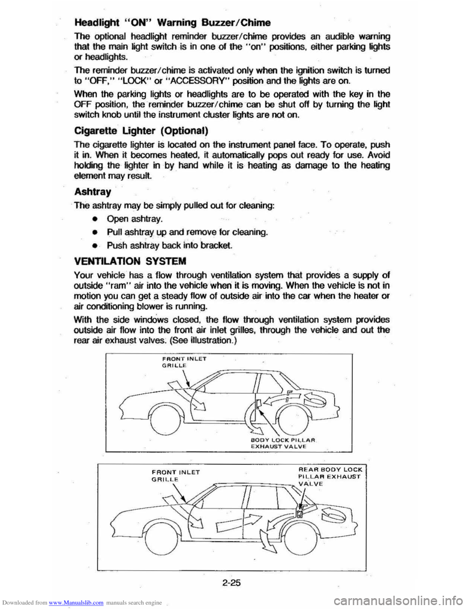
Your vehicle has a flow through ventilation system that provides a supply of outside "ram" air into the vehicle ' when it is moving . When the vehicle is not in
motion you can get a steady flow of outside air into the car when the heater or
air conditioning blower is running.
With the side
windOws closed, the flow lIYough ventilation system provides
outside air flow into the front air inlet grilles, through the vehicle and out the
rear air exhaust valves. (See illustration .)
FRONT INLET
2-25
REAR BODY LOCK PILLAR EXHAUST
Page 42 of 105
Downloaded from www.Manualslib.com manuals search engine Operating Tips
• Clear snow and ice from the hood and air inlet in front of the windshield . This helps the heater and defroster work better and reduces the chance 01 fogging the inside 01 the windshield .
•
Run the blower on "HI" for a few moments belore driving off. This helps
clear the intake ducts of snow and moisture and reduces the chance of
logging on the inside
01 the windows.
• Always keep the front inlet grilles clear of obstructions (leaves, ice, snow ,
etc .) .
• Always keep the underseat air path clear of objeCts .
Lower Air Vents
Two control handles located beneath the center instrument panel open (pull)
and close (full in ) the lower "ram " air vents. The amount of air discharged at these lower ·outlets increases with vehicle speed. Maximum airflow can be
obtained by opening any of the .side door windows approximately six inches. If so equipped, the rear quarter swing-out windows will"optimize lower vent
performance and provide maximum airflow without opening a side door glass . In this condition, minimum air buffeting and road noise is incurred.
HEATER SYSTEM (NON-AIR CONOmONEO SYSTEM)
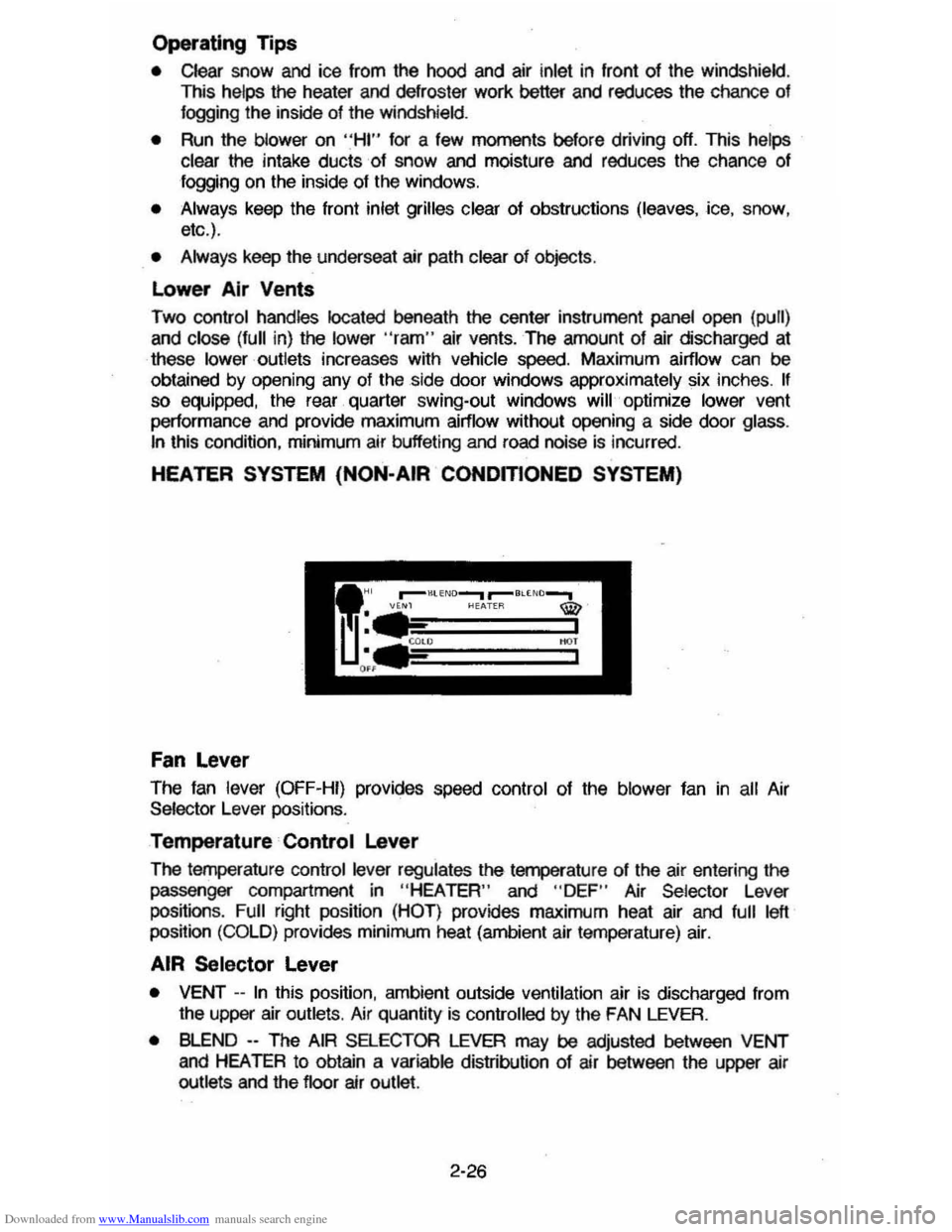
Fan lever
The fan lever (OFF-HI) provides speed control of the blower fan in all Air Selector Lever pOSitions.
Temperature Control lever
The temperature control lever regulates the temperature 01 the air entering the
passenger compartment in
"HEA TEA" and " DEF " Air Selector Lever
positions . Full right position (HOT ) provides maximum heat air and full left position (COLD) provides minimum heat (ambient air temperature) air.
AIR Selector lever
• VENT --In this position, ambient outside ventilation air is discharged from the upper air outlets . Air quantity is controlled by the FAN LEVER.
• BLEND --The AIR SELECTOR LEVER may be adjusted between VENT and HEATER to obtain a variable distribution of air between the upper air outlets and the floor air outlet.
2-26
Page 43 of 105
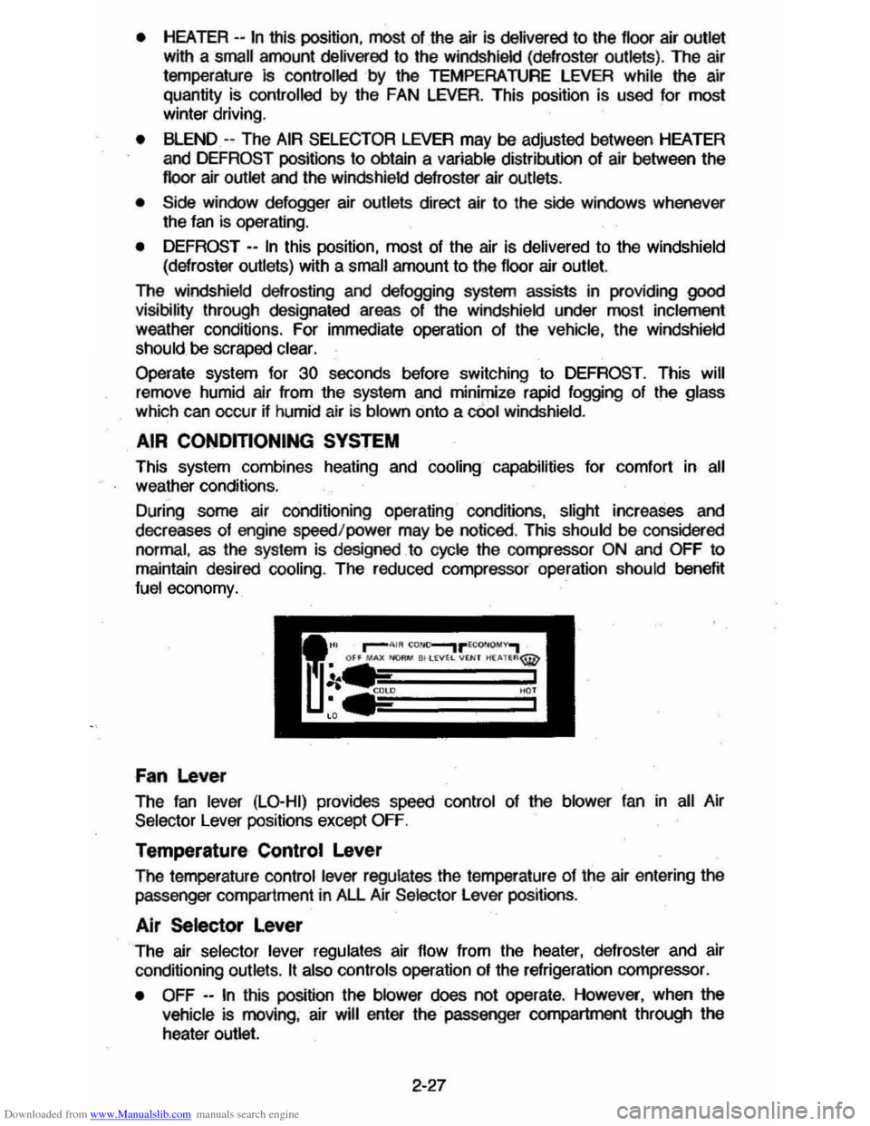
Downloaded from www.Manualslib.com manuals search engine • HEATER --In this position, most of the air is delivered to the floor air outlet
with a small amount delivered to the windshield (defroster outlets). The air
temperature
Is controlled by the TEMPERATURE LEVER while the air
quantity
is controlled by the FAN LEVER. This position is used for most winter driving.
• BLEND -- The AIR SELECTOR LEVER may be adjusted between HEATER
and DEFROST positions to obtain a variable distribution of air between the
floor air outlet and the windsh ield defroster air outlets.
• Side window defogger air outlets direct air to the side windows whenever
the fan is operating.
•
DEFROST - -In this poSition, most of the air is delivered to the windshield
(defroster outlets) with a small amount
to the floor air outlet.
The windshield defrosting and defogging system assists in providing
good visibility through designated areas of the windshield under most inclement
weather conditions . For immediate operation of the vehicle, the windshield
should be scraped clear.
Operate system for 30 seconds before switching to DEFROST . This will
remove humid air from the system
and minimize rapid fogging of the glass
which can occur if humid air Is blown onto a cOol windshield .
AIR CONOmONING SYSTEM
This system combines heating and cOOling capabilities for comfort in all weather conditions.
During some air conditioning operating conditions, slight increases and
decreases of engine speed/power may be noticed . This
should be considered
normal, as the system is designed to cycle the compressor
ON and OFF to
maintain desired cooling. The reduced compressor operation should
benef~ fuel economy.
Fan Lever
The fan lever (LO-HI) provides speed control of the blower fan in all Air
Selector Lever positions except
OFF.
Temperature Control Lever
The femperature control lever regulates the temperature of the air entering the passenger compartment in All Air Selector Lever positions .
Air Selector Lever
The air selector lever regulates air flow from the heater, defroster and air
conditioning outlets.
It also controls operation of the refrigeration compressor.
•
OFF --In this position the blower does not operate . However, when the
vehicle is moving, air will enter the· passenger compartment through the
heater outlet.
2-27
Page 44 of 105
Downloaded from www.Manualslib.com manuals search engine • MAX (AIR COND) --Air from the passengel' cOlTlpaftment is mixed with a small amount of outside air. conditioned and discharged from !he upper
outlets . This position. with the temperature
lever in full COLD. is used for
maximum cooling under conditions of high temperature and humidity .
• NORM (AIR COND) --Outside air is conditioned as ~ passes through the
system and is discharged from the upper outlets. This position is used for most air conditioning situations.
• BI-LEVEL (AIR COND) --Outside air is conditioned and directed out the
upper outlets PLUS the heater outlet. This position provides comfort and
keeps the windshield clear under low fogging conditions .
• VENT (ECONOMY) --Outside air is discharged from the upper outlet s. This position is provided for cool to moderate weather operation when
refrigeration is not required. The refrigeration compressor is turned off.
Operating Information -The engine cooling fan is automatically engaged in all air conditioning modes and defrost mode (with high air conditioning pressure).
• HEATER (ECONOMY) --Outside air is delivered from the heater outlet with
a small amount from the defroster outlets and the side window . defogger outlets. This position is used for most winter driving. The air conditioning compressor is turned off.
• DEFROST c_ Outs ide air is cond~ioned and delivered from the defroster
outlets w i1h a small amount from the heater outlet. This position is
recommended for conditions of severe fogging and icing
only.
Operating Tip
For satisfactory operation of the air conditioning system. windows should always be closed, except for the first two or three minutes to remove hot air if
the car has been closed. This provides a fast cool-down in normal air
conditioning mode.
ELECTRO-CLEAR REAR WINDOW DEFOGGER
The optional defogger consists of a heating element bonded to the inside
surface
of the rear glass . The unit is operated by a switch on the instrument panel and functions only in the ON position. When activated an indicator light
will illuminate.
After the defogger has operated for a short time. the system will
automatically shut off. If further defrosting or defogging is desired . simply actuate the switch again.
The defogger
will not function if the ignition is turned off.
Refrain from removing decals or other materjal' from the inside of rear window
with a razor or other sharp instrument since this may damage . the heating
element.
Clear snow and ice from the rear window to improve tihe efficiency of the rear
window defogger.
2-28
Page 62 of 105
Downloaded from www.Manualslib.com manuals search engine coolant level in the see-through recovery tank. The coolant level should be at
or above the
"FULL HOT" mark on the recovery tank.
CAUTION: Keep hand., toots and clothing -away from the engine COOling fa", to help prevent personIl intUry. lhiIlan is electric and can come on whether Or not the engine Is rUnning. 111. tan can start automatically In .respon .. to a heat sensor when the ignition Is in "Run."
Make sure the water pu"",, belts are not broken, or off the pulleys , and that the fan runs when the engine is running and there is an indication on the instrument panel of an overheat condition.
If the coolant level in the recovery tank is low, look for leaks at the radiator
hoses and connections, heater hoses and connections, radiator I and water pump. If you find major leaks, or spot other problems that may have caused
the engine to overheat,
do not run the engine untilthese problems have been
corrected. If you do not find a leak or other problem, caretully add coolant to
the recovery tank. (Coolant is a mixture of ethylene glycol antifreeze and water; see "Engine Cooling System" in "'Service and Maintenance," Section 5, for the proper antifreeze and mixture.) .
CAUTION: Under: some:' conditione, the ethylen~ glycol In engine coolant Is . combustible. -To help avoid being burned, DO NOT spill antifreeze or coolant on the exhauat system or hot engine parts..
If the coolant level in the recovery tank is at the correct level but there is still
an indication on the instrument panel of an overheat condition:
•
You may add coolant directly to the radiator. YOU MUST LET ENGINE COOL FIRST. See "Coolant Replacement" under "Engine Cooling
System"
in Section 5, "Service and Maintenance" in this manual. Follow steps t through 3 for the correct way to remove the radiator
cap
and add coolant.
Once the Engine Coolant Temperature light has gone out (or the Engine Coolant Temperature gage no longer signals an overheat condition), you can
resume
driving at a reduced speed. Return to normal driving after about ten
minutes If the light does not come back on (or the gage pointer does not again
show
ao overheat condition).
tf no cause for the overheat condition was found, see a qualified service technician.
JACKING
CAUTION
To help avoid personal injury:
• FollOW all jacking and stowage instructions .
• Use jack only for lifting this vehicle during wheel change.
• Never get beneath the vehicle, start or run engine while vehicle is
supported by jack.
• Always securely restow spare tire (or flat tire) and all jacking equipment.
3-4
Page 94 of 105
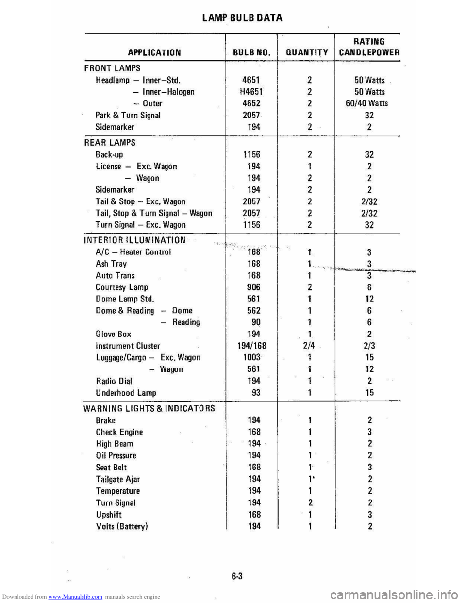
Downloaded from www.Manualslib.com manuals search engine LAMP BULB DATA
RATING
APPLICATION BULB NO. QUANTITY CANOLEPOWER
FRONT LAMPS
Headlamp -Inner-Std. 4651 2 50 Watts
-Inner-Halogen H4651 2 50 Watts
-Outer 4652 2 60/40 Watts
Park & Turn Signal 2057 2 32
Sidemarker 194 2 2
REAR LAMPS
Back-up 1156 2 32
license -Exc. Wagon 194 1 2
-Wagon 194 2 2
Sidemarker 194 2 2
Tail & Stop -Exc. Wagon 2057 2 2/32
Tail, Stop & Turn Signal -Wagon 2057 2 2/32
Turn Signal -Exc. Wagon 1156 . 2 32
INTERIOR ILLUMINATION
Ale -Heater Control
I
168 1
3
Ash Tray 168 1 3 ~-..... -Auto Trans 168 1
3
Courtesy lamp 906
I
2 6
Dome Lamp Std. 561 1 12
Dome & Reading -Dome 562
I
1 6
-Reading 90 1 6
Glove Box 194 1 2
instrument Cluster 194/168 2/4 2/3
Luggage/Cargo -Exc. Wagon 1003
I
1 15
-Wagon 561 1 12
Radio Dial 194 1 2
U nderhood lamp 93 1 15
WARNING LIGHTS & INDICATORS
Brake 194 1 2
Check Engine 168 1 3
High Beam 194 1 2
Oil Pressure 194
I
1 2
Seat Belt 168 1 3
Tailgate Ajar 194 l' 2
Temperature 194 1 2
Turn Signal 194 2 2
Upshift
I
168 1 3
Volts (Batter) 194 1 2 y
6·3
Page 96 of 105
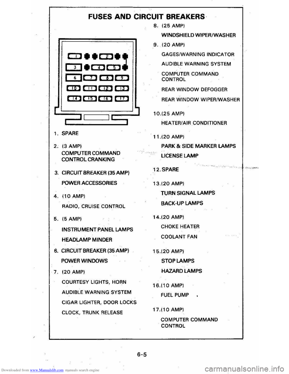
Downloaded from www.Manualslib.com manuals search engine FUSES AND CIRCUIT BREAKERS
8, 125 AMP)
r
CCl __ CD_:
OJ_COCD
CDC!J CDc::D
CD CIIl C!D r::m
em em em C!!l
,-II I~
1, SPARE
2, 13 AMPI
COMPUTER
COMMAND CONTROL CRANKING
3, CIRCUIT BREAKER (35 AMP)
POWER ACCESSORIES
4,110AMP)
RADIO, CRUISE CONTROL
5, 15 AMPI
INSTRUMENT PANEL LAMPS
HEADLAMP MINDER
6, CIRCUIT BREAKER (35 AMP)
POWER WINDOWS
7, 120 AMP)
COURTESY LIGHTS, HORN
AUDIBLE WARNING SYSTEM
CIGAR
LIGHTER, DOOR LOCKS
CLOCK,
TRUNK RELEASE
6-5
WINDSHIELD WIPER/WASHER
9, 120 AMP)
GAGES/WARNING INDICATOR
AUDIBLE WARNING SYSTEM
COMPUTER COMMAND
CONTROL
REAR WINDOW DEFOGGER
REAR WINDOW WIPER/WASHER
10,125
AMP)
HEATER/AIR
CONDITIONER
11,120 AMP)
PARK & SIDE MARKER LAMPS
LICENSE
LAMP
12,SPARE
13,120 AMP)
TURN SIGNAL LAMPS
BACK-UP LAMPS
14,120 AMP)
CHOKE HEATER
COOLANT FAN
15,(20 AMP)
STOP LAMPS
HAZARD LAMPS
16,110 AMP)
FUEL PUMP
17,110 AMP)
COMPUTER COMMAND
CONTROL
Page 100 of 105
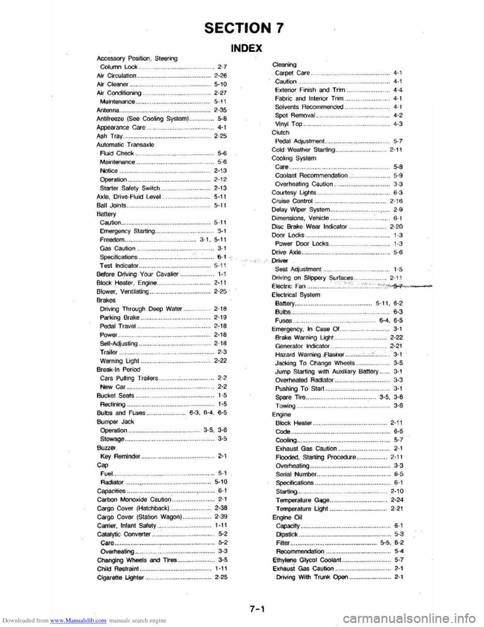
Downloaded from www.Manualslib.com manuals search engine SECTION 7
Accessory Position, Steering CoIl.m Lock 2-7 AIr Cir ctJlalioo. . 2-26 Ai' Cleaner. 5-,0 Air Conditio ning ............ . 2-27 M ainte nance .. Antenna . 5-\1 2 -35 5-8 Antifreeze (See Coo~ng System) .. Appearance cae ...• ....•.. 4·t .... ...... 2 -25 ASh Tra y .. Automatic T 'ansalC!e Fluid Chedi: . ___ .. . _ ..... _ ._ ... ... . Maintenance .. Notice ,. .. Op$ralion .. Surter Safety Switch Axlo, Drive-Fluid Level Ball Joints. Ba"&,y
· ....... 5-6 .... 5'-6 2,13 · .... 2 -12 2'13
........ . 5-11 5-1 I
Caution.. 5-11 Emergenc y Starling.. 3-1 Freedom.. .. 3·1 , 5-11 Gas caution . ___ ............. ..... ... . ...... .... 3·, Specilicalions .... ... ... ... .. ... .. .. . T esl indlealor .. Belor e Driving Your cavalier .. B loc k Healer, Engine Blower, Ventilating .. Brakes Driving Through Deep Water "
Parking Brake .. P eda l TraVel .. Power ... SelI·AqusIing ...... ... ..... .. ... .. .. . T railer ..... . Warning Light .. Br eak -In Period Cars Pulrng Tra~ars New Car .. Bucke l Seats .. R ttelininQ .. Bulbs and Fuses ..
""_ Jad< Operation . Stowage ............. ... ... .. .... •..•. • _ ..
Key RemiAder .. Cap FIJI:II .. R adiator Capa.cities .. carbon Monoxide Caution .. Cargo Cover (Hatchback) .. cargO Cover (Station Wagon) ... Carrier, Infant Safety .. cataIytlc Converter .. care .... OwNheatng ....... . Changing Wheels and Tl"es .. Ct\IICI Restraint.. Cigarette lightsr ..
. .... 6 -1 . . . 5-1 1 1-1 2-11 2-25
2 -18
2 -19
2·18 •.••.•. 2, 18 2-1 8 ....... ... .. 2· 3 2·22
2-2
2-2
1 -5
1-5
6 ·3. 6·4 . 6-5
3 ·5 . 3-6 ........ . 3-5
· ....... 2·'
5 -1 5-10 .... .. 6-1 2 -1 2-38 2 -39 1·11 5-2 ...... .... 5-2 ..3 -3 ....•.••. . 3·5 1-11 · ..... 2-25
INDEX
7-1
C1eri'9 c;a.pet care .. Caution .. Exteriof Finish and Trim Fabri c and Interio r Trim .. Solvents Racomme nded Spot Removal. Vinyl Top .. C kl tch
. .... 4·' . ..... 4 -' 4 -' 4 -1
4 -1
..,
4-3
PeDa l Acl/Ustmeot ........ ... ... ... .......... ........ 5·7 Cold Wealhet Starting ... ... ... ...... ... ... ...... 2·11 CooIiIl9 System care. .. . 5 ·8 Coolan t Rocommeodation 5-9 Overhea ting caution. 3-3 Courtosy Lights .. 6-3 Cruis e Con trof 2-16 Defay Wipo( Sys tem ....................... ,.. 2 -9 [)jmensions, Ve)jcle.. . ......... 6-1 [Xsc Brake Wear IrKicator .......... 2-20 Door locks ' -3 Power Door l ocks ... Drive Axle
"""" Seal Adjus tment. .. Driving on Slippery Surfaces Electn c Fan .. Electric al System Battory .. Bulbs .• . . FI.ISOS ..•..• Emergency. In Case Of . Brake W~ning Liglt .. 1
-3
.• 5·6
1 -5 2 -\' .... ~::<',~~-
5 '11, 6·2 '·3 6-4. 6·5 . .... ..... .. 3 · . ... 2 ·22 Geoefator hdicalor... . ...... 2 ·2 1 Hazru"d Warring . .,fLashef ... -'. __ .... ,,, 3 ·1 Jaddng T o Change Wheels 3·5 Jump Starling with Auxi~ary Banel)'. . 3· Overhe.1tod Radiator.. 3·3 Pushing To Start.. 3-I Spar e Trre.. . . .................... 3-5 , 3·6 Towing.. 3·6 Engine Block Heater ... Codo .. CooIO>g •••.
2 ·' , . . .. . 6·5
5 ·7
8I:haust Gas Caution ............... ... ... ... ... 2-1 Flooded, Staring Procedlre ................ 2·11 Qvome ating ................... ....... .... ............. . 3-3 Serial NulTlbef.. . .... 6-5 Specifications . ............... . ..... . .. ..... .......... 6-' Starting... 2·10 Temperature Gage.. 2 ·24 TefTlP(Iralure Light. 2 -21 EnginO Oil Capacity .. Dipstick •• F~Of . . .
. ............ ....... ... .. .... .......... ... 6-1
Reoo .. wnonootion .. Ethyteno Glycol Coolant .• EXhaUst Gas Caution . .
• •••• 5 -3 5·5. 6 ·2
5 ·'
5 ·7 . ....... 2·' Driving With Trunk Open ..... .. ............. . 2-'