load capacity CHEVROLET CAVALIER 1984 1.G Owners Manual
[x] Cancel search | Manufacturer: CHEVROLET, Model Year: 1984, Model line: CAVALIER, Model: CHEVROLET CAVALIER 1984 1.GPages: 105, PDF Size: 24.23 MB
Page 19 of 105
Downloaded from www.Manualslib.com manuals search engine Now and then, check that all trailer hitch bolts and nuts are tight. Also see the
Maintenance
Schedule folder, and thelndax in this manual , for important facts
on
belts , cooling system care and brake ~tment.
Break-In Schedule
See the new vehicle break-in information in this manual. Also, we recommend
you drive your new vehicle for 500 miles (800 kilometers) before trailer towing.
At the end of this 500 mile (800 kilometer) break-in period, avoid speeds over
50 mph (80 km/h) and full throttle starts during the first 500 miles (800 kilometers) of trailer towing .
CAUTION:
BRAKES-To help avoid personal injury due to poor braking action :
•
Trailer brakes of adequate size are required on trailers more than 450
kilograms (1,000 pounds) loaded weight.
• If you use trailer brakes with this vehicle, follow the instailation and balance instructions of the trailer brake manufacturer.
• Do not tap into the vehicle's brake system iUhe trailer brake system uses
more than 0.3 cubic centimeter (0.02 cubic inches) 01 fluid from the
vehicle 's
mast.". cyllnd<1r .. , In this case, the vehicle's brake fluid capacity will not be enough to operate both thevehicte and trailer brakes under all kinds
of use.
• All brake fluid parts must be able to stand 20 650 kPa (3,000 psi) . The
brake fluid tap must be made at the upper rear master cylinder port.
Copper tubing is subject to fatigue failure and must not be used.
HITCHES-To help avoid personal injury due to sway caused by such things as
crosswinds, large trucks passing or road roughness , or due to separation of
the trailer :
• A properly installed and adjusted (1) frame mounted, weight-dstribut ing hitch and (2) sway control witheoough capacity are required for trailers
more than 900 kilograms (2,000 pounds) loaded weight.
• Keep the trailer tongue load at 10 percent of the loaded trailer weight for
dead-weight hitches and 12 percent for weight-distributing hitches. Tongue
loads can be adjusted by proper distribution of the load in the trailer. This
can
be checked by weighing separately the loaded trailer and then the
tongue .
• Do not use axle-mounted Mches. They can damage the axle housing , wheel bearings , wheels or tires.
• Do not allow steel hitch parts to be in direct contact with aluminum bumper
parts, if so equipped. When steel and aluminum are in contact, a galvanic
reaction (a form of corrosion) can occur which will progressively lessen the
strength of the contacting metals to the point
of failure. An organic
compound or paint should
be used as a barrier on the contacting surfaces
and on the attaching fasteners.
• When you remove a trailer hitch, be sure to seal any mounting holes in the body. This will help prevent entry 01 exhaust fumes,
"Starting and Operating ," Section 2 ollhis manual.)
2-3
Page 34 of 105
Downloaded from www.Manualslib.com manuals search engine When_ going up or down hills. it ~ ~ tor the vehk:1e to toM 011 to gain apHCI (.,.rticu"Y when towing I trailer), even though the Cruise Control is enpgecL • this happens while going up hin, merely depress the accelerator pedal to maintain the speed desired. If going down a hili steep enough to cau .. thl vehie'" to gain speed, depress the brake pedal •• which will both dl .. ngage the Cruise Control and help .lOw the vehicle. In addition, when going down a steep or lang grade . the transaxle shoUld be shifted into I lower gear to help control vehicte speed •• see "Descending A Grade " in "Starting and Operating," Section 2.
HORN
The horn on your vehicle is actuated by firmly pressing on the ped in the
center of the steering
wheel.
HAZARD WARNING FLASHER
The hazard warning flasher is covered in "In Case of Emergency," Section 3.
FLOOR CONTROLS
BRAKING SYSTEM
The regular braking system is designed for braking performance under a wide
range of driving cond~ions even when the vehicle is loaded to ~ lull rated
vehicle toad capacity .
CAUTION: Driving through water deep enough to wet brake components may cau .. the brakea nat to work .. welL -M a reaul, the vehIde wi. not aIow down .. the usu.I _, ond M may pull 10 "'" right Of ..... _ 0"'-""'11 to "'" _ tor _ .-.os,
-'1 "'" ...... lightly 10 check __ .... "-'"
Brake Warning lJg/rt
The brake system warning light is covered in the '.' lnstrumentPanel" section.
Vacuum Power Brakes
• the engine stops, do not pump the brakes. The system is designed to stop the vehicle with reserve power assist n the brake pedal is held dOwn. This
reserve is
greatly reduced each time you apply and release the brakes. II,
when you turn the atMring wheel during braking, the vehic:1e does not turn, don't push as hard on the brake pedal •.
Without power assist the vehicle can still be stopped by pushing much harder
on the brake
pedal. however. the stopping distance may be longer.
Brakes (Except ,Parking Brake)
H the brake pedaJ goes down farther than normal, ~ may be due to a lack of
adjustment of any rear drum
brakes. To find. out if this is the case. drive
backward and forward a few times. applying the brakes firmly when going in
each direction.
See your dealer n pedal height dOes not retum to normal, or there is a rapid
increase in pedal travel whether or not your vehicle has rear drum brakes. This
could be a sign of brake trOUble.
NOTICE: "FtidInsI the brake" by resting yow i0oi on thl brau pedal when you do not Intend 'to brake CIIf1 overhMI: the brIkM and ...... out the brake InInga and p..ts faster. , ThI. mIIy alSo dllNlge the brakes Mtd will wasta fuel.
2-18
Page 56 of 105
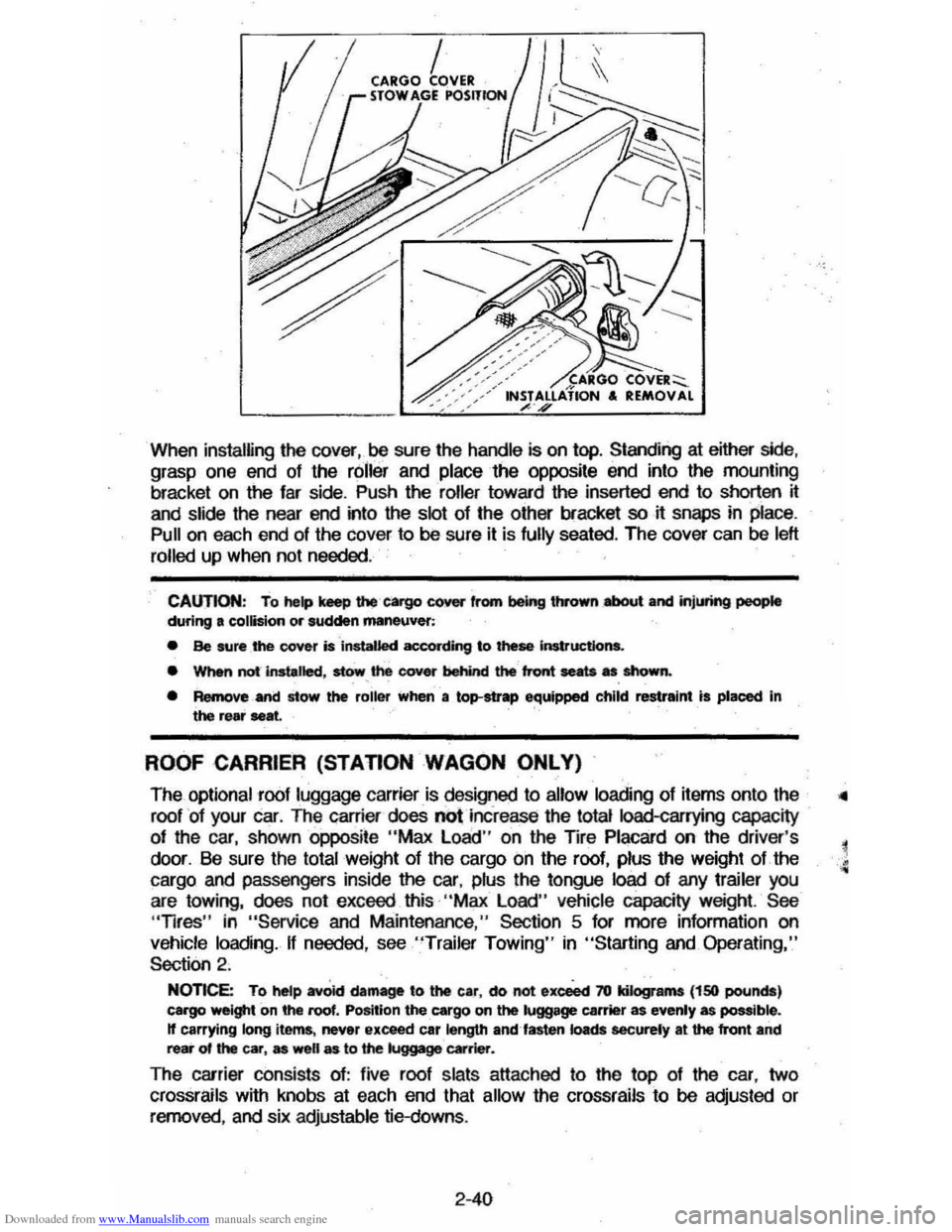
Downloaded from www.Manualslib.com manuals search engine When installing the cover,oo sure the handle is on top. Standing at either side, grasp one end of the roller and place the opposite end into the mounting
bracket on
the far side . Push the roller toward the inserted end to shorten it
and slide the near end into the slot of the other bracket so it snaps in place.
Pull on each end of the cover to 00 sure it is fully seated. The cover can be left
rolled
up when not needed .
CAUTION: To help keep u.., cargo cover from being thrown .,.a,oot and jnjlM'ing people during a collision or sudden maneuver:
• Be sure _the cover is installed according to these Instructions.
• WMn not-instalted, stow, the cover behind the front seats as shown.
• Remove and stow the roiler when a top-strap equipped child restraint is placed In the rear seat.
ROOF CARRIER (STAnON WAGON ONLY)
The optional roof luggage carrier is designed to allow loading of items onto the
roof
' of your car. The carrier does not increase the total Ioad-carrying capacity
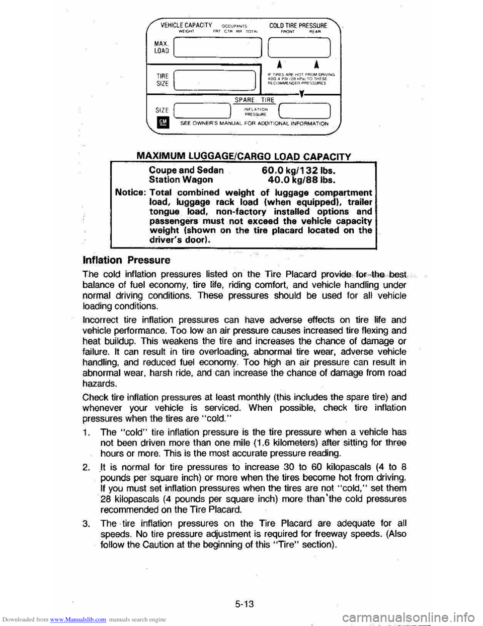
of the car, shown oppoSite "Max Load " on the TIre Placard on the driver's
door. Be sure the
total weight of the cargo on the roof, plus the weight of the
cargo and passengers inside
the car, plus the tongue load of any trailer you
are towing, does not exceed this· "Max Load" vehicle capacity weight. See "Tires" in "Service and Maintenance," Section 5 for more information on
vehicle loading. If needed, see "Trailer Towing" in "Starting and. Operating,"
Section 2 .
NOnce: To hetp avOid damage to the car, do not exceect 70 kilograms (150 pounds) cargo weight on the roof. Position the cargo on the luggage carrier as evenly as possible. If carrying long items , never exceed car length emUasten loads eacurely at the front and rear of the car, as well as to the luggage ~rier.
The carrier consists of: five roof slats attached to the top of the car, two
crossrails with knobs at each end that allow the crossrails to 00 adjusted or removed, and six adjustable tie-downs.
2-40
Page 86 of 105
Downloaded from www.Manualslib.com manuals search engine /" VEHICLE CAPACITY OCCUP."TS COLD TIRE PRESSURE ' , ~~, mT CtR RR TOTAL C_, ~E~R
MAX [ LOAD I [ 1
A A TIRE [ I
.. T"ES AAf ,.qT ,~o ... OONiNG '00' "50 ". 'P" TO THE'" SIZE R'V,""ME>.<:lEl) PR"5lJRES
SPARE TIRE ,
SIZE ( )
MAXIMUM LUGGAGE/CARGO LOAD CAPACITY
Coupe and Sedan Station Wagon 60.0 kg/' 321bs. 40.0 kg/88Ibs.
Notice: Total combined weight of luggage compartment load, luggage rack load (when equipped), trailer tongue load, non-factory installed options and
passenge'rs' must. not exceed the vehicle capacity weight (shown on the tire placard located on the driver's door).
Inflation Pressure
The cold inflation pressures listed on the Tire Placard provide forAIlebest
balance of fuel economy, tire life, riding comfort, and vehicle handling under normal driving conditions. These pressures should be used for all vehicle
loading conditions.
Incorrect tire inflation pressures can have adverse effects on tire life
and vehicle performance. Too Iowan air pressure causes increased tire flexing and
heat buildup. This weakens the tire and increases the chance of damage or
failure. It can result in tire overloading, abnormal tire wear, adverse vehicle handling, and reduced fuel economy. Too high an air pressure can result in
abnormal wear, harsh ride, and can increase the chance of damage from road
hazards.
Check tire inflation pressures at
least monthly (this includes the spare tire) and
whenever your vehicle is serviced. When possible, check tire inflation
pressures
when the tires are "cold."
1. The "cold" tire inflation pressure is the tire pressure when a vehicle has
not been driven more than one mile (1.6 kilometers) after sitting for three
hours or
more. This is the most accurate pressure reading.
2. .It is normal for tire pressures to increase 30 to 60 kilopascals (4 to 8 pounds per square inch) or more when the tires become hot from driving.
If you must set inflation pressures when the tires are not "cold," set them
28 kilopascals (4 pounds per square inch) more than'the cold pressures
recommended on the Tire Placard.
3. The· tire inflation pressures on the Tire Placard are adequate for all speeds. No tire pressure adjustment is required for freeway speeds. (Also
follow
the Caution at the beginning of this "Tire" section).
5-13
Page 89 of 105
Downloaded from www.Manualslib.com manuals search engine • Install the chains on the front tires as tightly as possible, then tighten them
again after driving 1/4 to 1/2 mile (0.4 to 0.8 kilometer). The use of chains
on the rear tires is not recommended; the chains may contact and
possibly damage the vehicle. If you intend to use chains on the rear tires, be sure
there is enough clearance.
• Do not exceed 45 mph (70 km/h), or the chain manufacturer's speed limitation, if lower.
• Drive in a restrained manner and avoid large bumps, potholes, severe turns and other manuevers which CQuid cause the tires to bounce up and down.
• Follow any other instructions of the chain manufacturer which do not
disagree with the above.
Spare Tire
For the use and installation of your spare tire, see "In Case of Emergency,"
Section 3 of this manual.
Tire Replacement
CAUTION:" 00 not mix different tire construction types (such as radial, bias, and biasbetted) on your vehicle exceptio emergencies, because your vehicle's handling could be affected and may result in loss Of control. This caution does not apply to a compact spare tire furnished with your vehicle.
On most vehicles originally eqUipped with radial tires, you will find a TPC Spec.
No. (Tire Performance Criteria Specification Number)
molded into the tire
sidewall
near the tire size marking. This shows that the tire meets rigid size
and performance standards which were developed for your vehicle. The TPC
Spec. No. assures a proper combination of endurance,
handHng, load capacity,
ride and traction on wet, dry, or snow-covered surfaces. When you replace your tires with tires having the same TPC Spec. No., your new tires will be
compatible with your vehicle.
When replacing tires with those not having a TPC Spec. No., you should use
the same size, load range, and construction type (bias, bias-belted, or radial)
as the original tires on your vehicle. A different size or type of tire may affect
such things as ride, handling, speedometer/odometer calibration, vehicle
ground clearance, and tire or tire chain clearance to the body or chassis. If
replacing only a single tire, it should be paired on the same axle with the least worn tire of the other three.
Uniform Tire Quality Grading
The following information relates to the tire grading system developed by the
United States
National Highway Traffic Safety Administration which will grade
tires by traction and temperature performance. (This applies only to vehicles
sold in the United States.)
Traction -A, B, C
The traction grades, from highest to lowest are: A, S, and C. They represent
the tire's
::ability to stop on wet pavement as measured under controlled
conditions on specified government test
~urfaces of asphalt and concrete. A
tire marked C may have poor traction performance.
Warning: The traction grade assigned to this tire is based on braking (straight
ahead) traction tests
and does not include cornering (turning) traction.
5-16
Page 100 of 105
Downloaded from www.Manualslib.com manuals search engine SECTION 7
Accessory Position, Steering CoIl.m Lock 2-7 AIr Cir ctJlalioo. . 2-26 Ai' Cleaner. 5-,0 Air Conditio ning ............ . 2-27 M ainte nance .. Antenna . 5-\1 2 -35 5-8 Antifreeze (See Coo~ng System) .. Appearance cae ...• ....•.. 4·t .... ...... 2 -25 ASh Tra y .. Automatic T 'ansalC!e Fluid Chedi: . ___ .. . _ ..... _ ._ ... ... . Maintenance .. Notice ,. .. Op$ralion .. Surter Safety Switch Axlo, Drive-Fluid Level Ball Joints. Ba"&,y
· ....... 5-6 .... 5'-6 2,13 · .... 2 -12 2'13
........ . 5-11 5-1 I
Caution.. 5-11 Emergenc y Starling.. 3-1 Freedom.. .. 3·1 , 5-11 Gas caution . ___ ............. ..... ... . ...... .... 3·, Specilicalions .... ... ... ... .. ... .. .. . T esl indlealor .. Belor e Driving Your cavalier .. B loc k Healer, Engine Blower, Ventilating .. Brakes Driving Through Deep Water "
Parking Brake .. P eda l TraVel .. Power ... SelI·AqusIing ...... ... ..... .. ... .. .. . T railer ..... . Warning Light .. Br eak -In Period Cars Pulrng Tra~ars New Car .. Bucke l Seats .. R ttelininQ .. Bulbs and Fuses ..
""_ Jad< Operation . Stowage ............. ... ... .. .... •..•. • _ ..
Key RemiAder .. Cap FIJI:II .. R adiator Capa.cities .. carbon Monoxide Caution .. Cargo Cover (Hatchback) .. cargO Cover (Station Wagon) ... Carrier, Infant Safety .. cataIytlc Converter .. care .... OwNheatng ....... . Changing Wheels and Tl"es .. Ct\IICI Restraint.. Cigarette lightsr ..
. .... 6 -1 . . . 5-1 1 1-1 2-11 2-25
2 -18
2 -19
2·18 •.••.•. 2, 18 2-1 8 ....... ... .. 2· 3 2·22
2-2
2-2
1 -5
1-5
6 ·3. 6·4 . 6-5
3 ·5 . 3-6 ........ . 3-5
· ....... 2·'
5 -1 5-10 .... .. 6-1 2 -1 2-38 2 -39 1·11 5-2 ...... .... 5-2 ..3 -3 ....•.••. . 3·5 1-11 · ..... 2-25
INDEX
7-1
C1eri'9 c;a.pet care .. Caution .. Exteriof Finish and Trim Fabri c and Interio r Trim .. Solvents Racomme nded Spot Removal. Vinyl Top .. C kl tch
. .... 4·' . ..... 4 -' 4 -' 4 -1
4 -1
..,
4-3
PeDa l Acl/Ustmeot ........ ... ... ... .......... ........ 5·7 Cold Wealhet Starting ... ... ... ...... ... ... ...... 2·11 CooIiIl9 System care. .. . 5 ·8 Coolan t Rocommeodation 5-9 Overhea ting caution. 3-3 Courtosy Lights .. 6-3 Cruis e Con trof 2-16 Defay Wipo( Sys tem ....................... ,.. 2 -9 [)jmensions, Ve)jcle.. . ......... 6-1 [Xsc Brake Wear IrKicator .......... 2-20 Door locks ' -3 Power Door l ocks ... Drive Axle
"""" Seal Adjus tment. .. Driving on Slippery Surfaces Electn c Fan .. Electric al System Battory .. Bulbs .• . . FI.ISOS ..•..• Emergency. In Case Of . Brake W~ning Liglt .. 1
-3
.• 5·6
1 -5 2 -\' .... ~::<',~~-
5 '11, 6·2 '·3 6-4. 6·5 . .... ..... .. 3 · . ... 2 ·22 Geoefator hdicalor... . ...... 2 ·2 1 Hazru"d Warring . .,fLashef ... -'. __ .... ,,, 3 ·1 Jaddng T o Change Wheels 3·5 Jump Starling with Auxi~ary Banel)'. . 3· Overhe.1tod Radiator.. 3·3 Pushing To Start.. 3-I Spar e Trre.. . . .................... 3-5 , 3·6 Towing.. 3·6 Engine Block Heater ... Codo .. CooIO>g •••.
2 ·' , . . .. . 6·5
5 ·7
8I:haust Gas Caution ............... ... ... ... ... 2-1 Flooded, Staring Procedlre ................ 2·11 Qvome ating ................... ....... .... ............. . 3-3 Serial NulTlbef.. . .... 6-5 Specifications . ............... . ..... . .. ..... .......... 6-' Starting... 2·10 Temperature Gage.. 2 ·24 TefTlP(Iralure Light. 2 -21 EnginO Oil Capacity .. Dipstick •• F~Of . . .
. ............ ....... ... .. .... .......... ... 6-1
Reoo .. wnonootion .. Ethyteno Glycol Coolant .• EXhaUst Gas Caution . .
• •••• 5 -3 5·5. 6 ·2
5 ·'
5 ·7 . ....... 2·' Driving With Trunk Open ..... .. ............. . 2-'