CHEVROLET CORVETTE 1996 4.G Owners Manual
Manufacturer: CHEVROLET, Model Year: 1996, Model line: CORVETTE, Model: CHEVROLET CORVETTE 1996 4.GPages: 386, PDF Size: 20.12 MB
Page 111 of 386
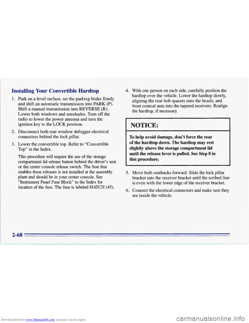
Downloaded from www.Manualslib.com manuals search engine Installing Your Convertible Hardtop
1. Park on a level surface, set the parking brake firmly
and shift an automatic transmission into
PARK (P).
Shift a manual transmission into REVERSE (R).
Lower both windows and sunshades. Turn off the
radio to lower the power antenna and turn the
ignition key to the
LOCK position.
2. Disconnect both rear window defogger electrical
3. Lower the convertible top. Refer to “Convertible
connectors
behind the lock pillar.
Top” in the Index.
This procedure will require the use of the storage
compartment lid release button behind the driver’s seat
or the center console release switch. The fuse that
enables these releases is not installed at the assembly
plant and should
be in your center console. See
“Instrument Panel Fuse Block” in the Index for
location of the fuse. The fuse is labeled HATCH (45). 4. With
one person on each side, carefully position the
hardtop over the vehicle. Lower the hardtop slowly,
aligning the rear bolt spacers onto the bezels, and
front conical nuts into the tapered receivers. Realign
the hardtop, if necessary.
NOTICE:
To help avoid damage, don’t force the rear
of the hardtop
down. The hardtop may rest
slightly above the storage compartment lid
until the release lever
is pulled. See Step 8 in
this procedure.
5. Move both seatbacks forward. Slide the lock pillar
bracket into the receiver bracket until the scribed line
is even with the lower edge of the receiver bracket.
6. Connect the electrical connectors and make sure they
are inside the vehicle.
Page 112 of 386
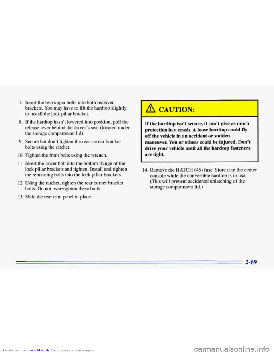
Downloaded from www.Manualslib.com manuals search engine 7.
8.
9.
Insert the two upper bolts into both receiver
brackets. You may have to lift the hardtop slightly
to install the lock pillar bracket.
If the hardtop hasn’t lowered into position, pull the
release lever behind the driver’s seat (located under the storage compartment lid).
Secure but don’t tighten the rear corner bracket
bolts using the ratchet.
10. Tighten the front bolts using the wrench.
11. Insert the lower bolt into the bottom flange of the
lock pillar brackets and tighten. Install and tighten
the remaining bolts into the lock pillar brackets.
12. Using the ratchet, tighten the rear corner bracket
bolts.
Do not over-tighten these bolts.
13. Slide the rear trim panel in place.
If the hardtop isn’t secure, it can’t give as much
protection in a crash.
A loose hardtop could fly
off the vehicle in an accident or sudden
maneuver. You or others could be injured. Don’t
drive your vehicle until all the hardtop fasteners
are tight.
14. Remove the HATCH (45) fuse. Store it in the center
console while the convertible hardtop is in use.
(This will prevent accidental unlatching of the
storage compartment lid.)
2-69
Page 113 of 386
Downloaded from www.Manualslib.com manuals search engine Instrument Panel
2-70
Page 114 of 386

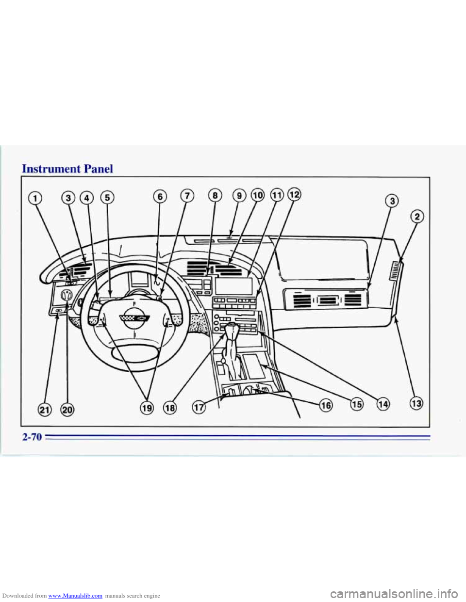
Downloaded from www.Manualslib.com manuals search engine 1. Acceleration Slip Regulation (ASR) Switch
2. Side Window Defogger Vent
3. Side Air Vent
4. Turn SignaVMultifunction Lever
5. Tilt Lever
6. Instrument Cluster
7. Ignition Switch
8. Trip Monitor Controls
9. Solar Sensor
10. Center Air Vent
1
1. Driver Information Center 12.
Comfort Controls
13. Fuse Panel
14. Audio System
15.
Ashtray/Lighter/Cupholder
16. Ride Control (Option)
17. Power Seat Control (Option)
18. Shift Lever (Automatic Shown)
19. Horn
20. Main Lamp Control
21. Fog Lamp Switch
2-71
Page 115 of 386
Downloaded from www.Manualslib.com manuals search engine Instrument Panel Cluster
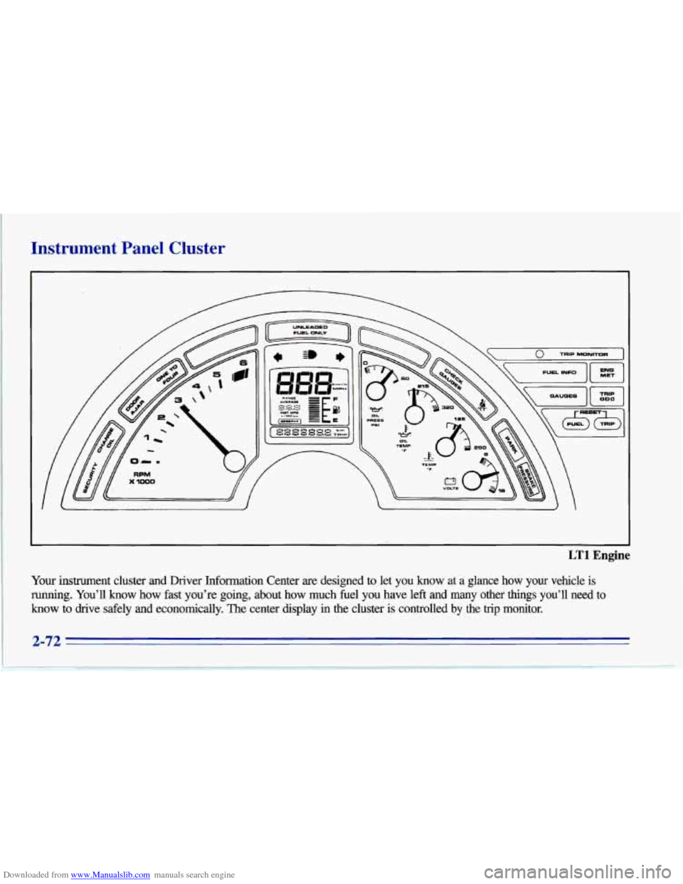
LT1 Engine
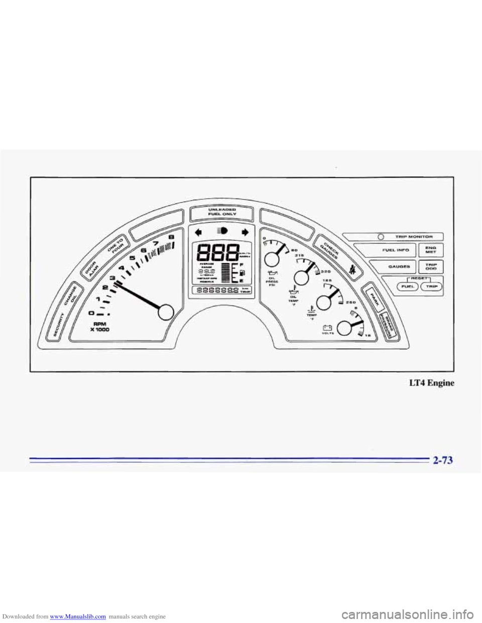
Your instrument cluster and Driver Information Center are designed to let you know at a glance how your vehicle is
running. You’ll know how fast you’re going, about how much fuel you have left and many other things you’ll need to
know to drive safely and economically. The center display in t\
he cluster is controlled
by the trip monitor.
Page 116 of 386
Downloaded from www.Manualslib.com manuals search engine LT4 Engine
2-73
Page 117 of 386
Downloaded from www.Manualslib.com manuals search engine Speedometer and Odometer
Your speedometer lets you see your speed in either miles Tachometer
per hour (mph) or kilometers p& how: (km/h). Your
odometer shows how far your vehicle has been driven, in The
tachometer displays the engine speed in thousands
either miles or kilometers. Press the
ENG MET button on of
revolutions per minute (rpm).
the trip monitor to switch the display between English
units (miles) and metric units (kilometers).
Your Corvette’s odometer is tamper-resistant. It will
read
OD0 ERR if someone has tampered with it.
If a new odometer is installed, it will automatically reset to
the correct reading.
If an electrical or other problem makes
setting the odometer correctly impossible, then it’s set at
zero, but
a label on the driver’s door must show the old
reading and when the new one was installed.
Trip Odometer
The trip odometer can tell you how far your Corvette has
been driven since you last set the trip odometer to zero.
To display the trip odometer, press TRIP
OD0 on the
Trip Monitor.
To reset it, press and hold RESET TRIP
for two seconds. Fuel
will shut
off at about 6400 rpm for the LT4 (Code 5)
engine and at about 5850 rpm for the LT1 (Code P)
engine.
If you continue to drive your Corvette
at the fuel shut
off rpm, you could damage your engine. Be sure to
operate your Corvette below the fuel shut
off rpm or
reduce your rpm quickly when the fuel shuts
off.
Warning Lights, Gauges and
Indicators
This part describes the warning lights and gauges that may
be on your vehicle. The pictures will help you locate them.
Warning lights and gauges can signal
that something is
wrong before it becomes serious enough to cause an
expensive repair or replacement. Paying attention to
your warning lights and gauges could also save you or
others from injury.
Page 118 of 386
Downloaded from www.Manualslib.com manuals search engine Warning lights come on when there may be or is a
problem with one of your vehicle’s functions.
As you will
see in the details on the next few pages, some warning
lights come on briefly when you
start the engine just to let
you know they’re working.
If you are farniliar with this
section, you should not be alarmed when this happens.
Gauges can indicate when there may be or
is a problem
with one of your vehicle’s functions. Often gauges and
warning lights work together to let
you know when
there’s a problem with your vehicle.
When one of the warning lights comes on and stays
on
when you are driving, or when one of the gauges shows
there may be a problem, check the section that tells you
what to do about it. Please follow this manual’s advice.
Waiting to do repairs can be costly
-- and even
dangerous.
So please get to know your warning lights
and gauges. They’re a big help.
Your vehicle also has a Driver Information Center that
works along with the warning lights and gauges. See
“Driver Information Center” in the Index.
Safety Belt Reminder Light
When the key is turned to RUN or START, a chime will
come on for about eight seconds to remind people to
fasten their safety belts, unless the driver’s safety belt is
already buckled.
The safety belt light will
also come on and stay on
until the driver’s belt is
buckled.
2-75
Page 119 of 386
Downloaded from www.Manualslib.com manuals search engine Air Bag Readiness Light
There is an air bag readiness light on the instrument
panel, which shows AIR BAG. The system checks the
air bag’s electrical system for malfunctions. The light
tells you if there is an electrical problem. The system
check includes the air bag sensors, the air bag modules,
the wiring
and the diagnostic module. For more
information on the air bag system, see “Air Bag” in
the Index.
AIR
BAG
You will see this light flash
for a few seconds when you
turn your ignition to RUN
or START. Then the light
should go out. This means
the system is ready.
If the air bag readiness light doesn’t come on when you
start your vehicle, or stays on,
or comes on when you
are driving, your air bag system may not work properly.
Have your vehicle serviced right away.
Charging System Indicator Light
-+I
This light will come on
when you turn on the
ignition, but the engine is
not running, as a check to
show you it is working. It
should go out when the
engine starts.
If it stays on or comes on while you are driving, you
may have a problem with the electrical charging system.
It could indicate that you have a loose or broken drive
belt or another electrical problem. Have it checked
right away. Driving while this light is on could drain
your battery.
If you must drive a short distance with the light on, be
certain to turn
off all your accessories, such as the radio
and air conditioner.
2-76
Page 120 of 386
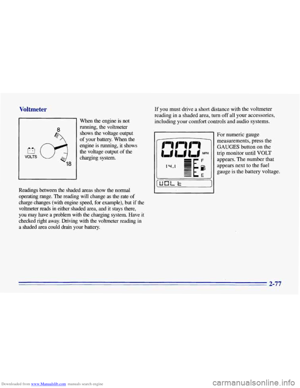
Downloaded from www.Manualslib.com manuals search engine Voltmeter
El
VOLTS
18
When the engine is not running, the voltmeter
shows the voltage output
of your battery.
When the
engine is running, it shows
the voltage output of the
charging system.
Readings between the shaded areas show the normal
operating range. The reading will change as the rate of
charge changes (with engine speed, for example), but
if the
voltmeter reads in either shaded area, and it stays there,
you may have a problem with the charging system. Have it
checked right away. Driving with the voltmeter reading
in
a shaded area could drain your battery. If you
must drive a short distance with the voltmeter
reading in a shaded area, turn
off all your accessories,
including your comfort controls and audio systems.
For numeric gauge
measurements, press the
GAUGES button on the
trip monitor until
VOLT
appears. The number that
appears next to the fuel
gauge is the battery voltage.
2-77