mirror CHEVROLET DYNASTY 1993 Service Manual
[x] Cancel search | Manufacturer: CHEVROLET, Model Year: 1993, Model line: DYNASTY, Model: CHEVROLET DYNASTY 1993Pages: 2438, PDF Size: 74.98 MB
Page 22 of 2438
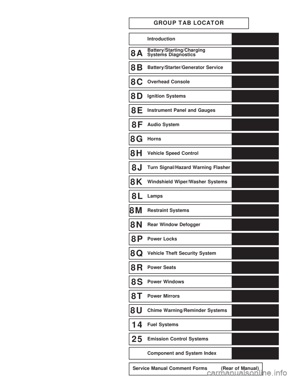
GROUP TAB LOCATOR
Introduction
8ABattery/Starting/Charging
Systems Diagnostics
8BBattery/Starter/Generator Service
8COverhead Console
8DIgnition Systems
8EInstrument Panel and Gauges
8FAudio System
8GHorns
8HVehicle Speed Control
8JTurn Signal/Hazard Warning Flasher
8KWindshield Wiper/Washer Systems
8LLamps
8MRestraint Systems
8NRear Window Defogger
8PPower Locks
8QVehicle Theft Security System
8RPower Seats
8SPower Windows
8TPower Mirrors
8UChime Warning/Reminder Systems
14Fuel Systems
25Emission Control Systems
Component and System Index
Service Manual Comment Forms (Rear of Manual)
Page 33 of 2438
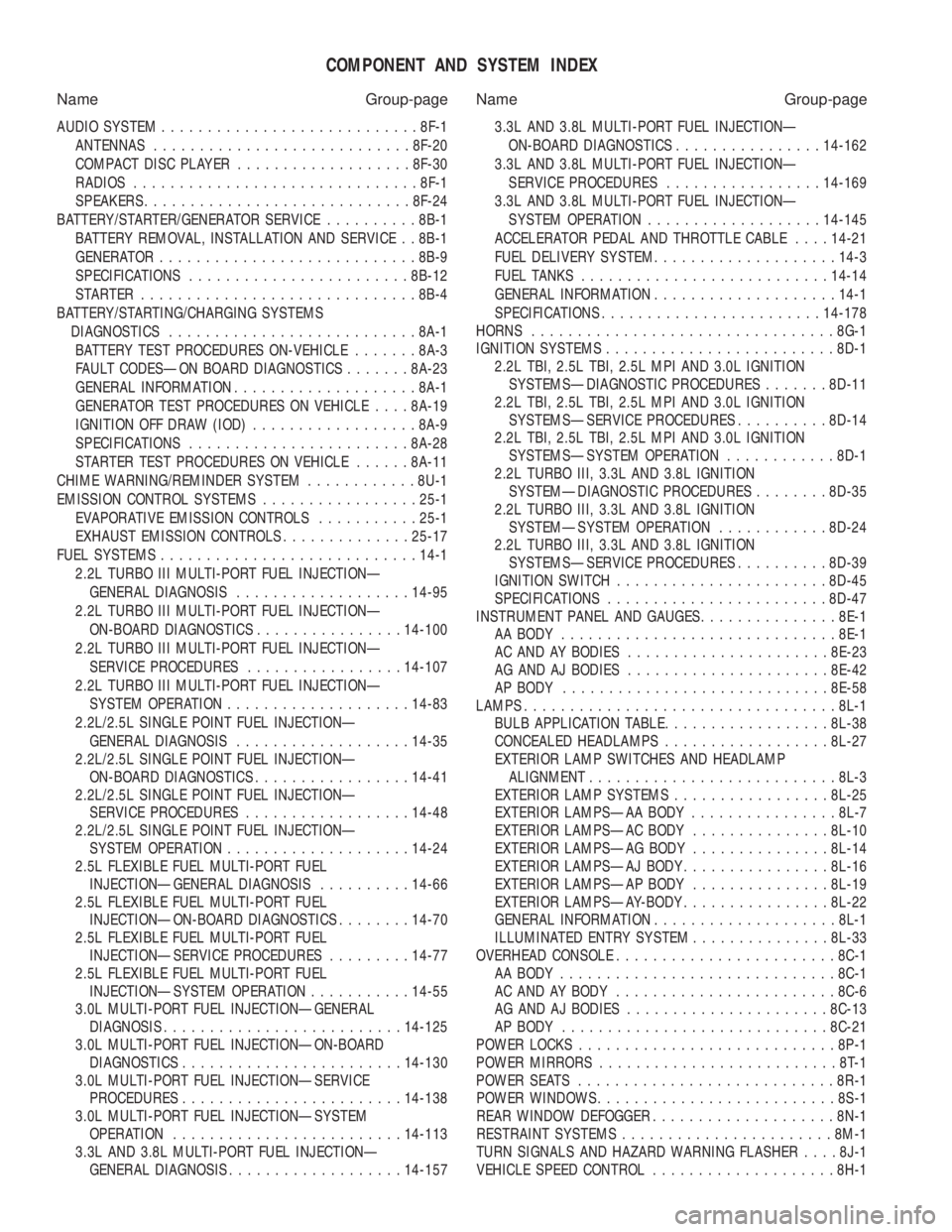
COMPONENT AND SYSTEM INDEX
Name Group-page Name Group-page
AUDIO SYSTEM ............................ 8F-1
ANTENNAS ............................ 8F-20
COMPACT DISC PLAYER ................... 8F-30
RADIOS ............................... 8F-1
SPEAKERS ............................. 8F-24
BATTERY/STARTER/GENERATOR SERVICE ..........8B-1
BATTERY REMOVAL, INSTALLATION AND SERVICE . . 8B-1
GENERATOR ............................ 8B-9
SPECIFICATIONS ........................ 8B-12
STARTER .............................. 8B-4
BATTERY/STARTING/CHARGING SYSTEMS DIAGNOSTICS ........................... 8A-1
BATTERY TEST PROCEDURES ON-VEHICLE .......8A-3
FAULT CODESÐON BOARD DIAGNOSTICS .......8A-23
GENERAL INFORMATION .................... 8A-1
GENERATOR TEST PROCEDURES ON VEHICLE ....8A-19
IGNITION OFF DRAW (IOD) ..................8A-9
SPECIFICATIONS ........................ 8A-28
STARTER TEST PROCEDURES ON VEHICLE ......8A-11
CHIME WARNING/REMINDER SYSTEM ............8U-1
EMISSION CONTROL SYSTEMS .................25-1
EVAPORATIVE EMISSION CONTROLS ...........25-1
EXHAUST EMISSION CONTROLS ..............25-17
FUEL SYSTEMS ............................ 14-1
2.2L TURBO III MULTI-PORT FUEL INJECTIONÐ GENERAL DIAGNOSIS ................... 14-95
2.2L TURBO III MULTI-PORT FUEL INJECTIONÐ ON-BOARD DIAGNOSTICS ................14-100
2.2L TURBO III MULTI-PORT FUEL INJECTIONÐ SERVICE PROCEDURES .................14-107
2.2L TURBO III MULTI-PORT FUEL INJECTIONÐ SYSTEM OPERATION .................... 14-83
2.2L/2.5L SINGLE POINT FUEL INJECTIONÐ GENERAL DIAGNOSIS ................... 14-35
2.2L/2.5L SINGLE POINT FUEL INJECTIONÐ ON-BOARD DIAGNOSTICS .................14-41
2.2L/2.5L SINGLE POINT FUEL INJECTIONÐ SERVICE PROCEDURES .................. 14-48
2.2L/2.5L SINGLE POINT FUEL INJECTIONÐ SYSTEM OPERATION .................... 14-24
2.5L FLEXIBLE FUEL MULTI-PORT FUEL INJECTIONÐGENERAL DIAGNOSIS ..........14-66
2.5L FLEXIBLE FUEL MULTI-PORT FUEL INJECTIONÐON-BOARD DIAGNOSTICS ........14-70
2.5L FLEXIBLE FUEL MULTI-PORT FUEL INJECTIONÐSERVICE PROCEDURES .........14-77
2.5L FLEXIBLE FUEL MULTI-PORT FUEL INJECTIONÐSYSTEM OPERATION ...........14-55
3.0L MULTI-PORT FUEL INJECTIONÐGENERAL DIAGNOSIS .......................... 14-125
3.0L MULTI-PORT FUEL INJECTIONÐON-BOARD DIAGNOSTICS ........................ 14-130
3.0L MULTI-PORT FUEL INJECTIONÐSERVICE PROCEDURES ........................ 14-138
3.0L MULTI-PORT FUEL INJECTIONÐSYSTEM OPERATION ......................... 14-113
3.3L AND 3.8L MULTI-PORT FUEL INJECTIONÐ GENERAL DIAGNOSIS ................... 14-157 3.3L AND 3.8L MULTI-PORT FUEL INJECTIONÐ
ON-BOARD DIAGNOSTICS ................14-162
3.3L AND 3.8L MULTI-PORT FUEL INJECTIONÐ SERVICE PROCEDURES .................14-169
3.3L AND 3.8L MULTI-PORT FUEL INJECTIONÐ SYSTEM OPERATION ................... 14-145
ACCELERATOR PEDAL AND THROTTLE CABLE ....14-21
FUEL DELIVERY SYSTEM .................... 14-3
FUEL TANKS ........................... 14-14
GENERAL INFORMATION .................... 14-1
SPECIFICATIONS ........................ 14-178
HORNS ................................. 8G-1
IGNITION SYSTEMS ......................... 8D-1
2.2L TBI, 2.5L TBI, 2.5L MPI AND 3.0L IGNITION SYSTEMSÐDIAGNOSTIC PROCEDURES .......8D-11
2.2L TBI, 2.5L TBI, 2.5L MPI AND 3.0L IGNITION SYSTEMSÐSERVICE PROCEDURES ..........8D-14
2.2L TBI, 2.5L TBI, 2.5L MPI AND 3.0L IGNITION SYSTEMSÐSYSTEM OPERATION ............8D-1
2.2L TURBO III, 3.3L AND 3.8L IGNITION SYSTEMÐDIAGNOSTIC PROCEDURES ........8D-35
2.2L TURBO III, 3.3L AND 3.8L IGNITION SYSTEMÐSYSTEM OPERATION ............8D-24
2.2L TURBO III, 3.3L AND 3.8L IGNITION SYSTEMSÐSERVICE PROCEDURES ..........8D-39
IGNITION SWITCH ....................... 8D-45
SPECIFICATIONS ........................ 8D-47
INSTRUMENT PANEL AND GAUGES ...............8E-1
AA BODY .............................. 8E-1
AC AND AY BODIES ...................... 8E-23
AG AND AJ BODIES ...................... 8E-42
AP BODY ............................. 8E-58
LAMPS .................................. 8L-1
BULB APPLICATION TABLE ..................8L-38
CONCEALED HEADLAMPS ..................8L-27
EXTERIOR LAMP SWITCHES AND HEADLAMP ALIGNMENT ........................... 8L-3
EXTERIOR LAMP SYSTEMS .................8L-25
EXTERIOR LAMPSÐAA BODY ................8L-7
EXTERIOR LAMPSÐAC BODY ...............8L-10
EXTERIOR LAMPSÐAG BODY ...............8L-14
EXTERIOR LAMPSÐAJ BODY ................8L-16
EXTERIOR LAMPSÐAP BODY ...............8L-19
EXTERIOR LAMPSÐAY-BODY ................8L-22
GENERAL INFORMATION .................... 8L-1
ILLUMINATED ENTRY SYSTEM ...............8L-33
OVERHEAD CONSOLE ........................ 8C-1
AA BODY .............................. 8C-1
AC AND AY BODY ........................ 8C-6
AG AND AJ BODIES ...................... 8C-13
AP BODY ............................. 8C-21
POWER LOCKS ............................ 8P-1
POWER MIRRORS ..........................8T-1
POWER SEATS ............................ 8R-1
POWER WINDOWS .......................... 8S-1
REAR WINDOW DEFOGGER .................... 8N-1
RESTRAINT SYSTEMS ....................... 8M-1
TURN SIGNALS AND HAZARD WARNING FLASHER ....8J-1
VEHICLE SPEED CONTROL .................... 8H-1
Page 337 of 2438
CLUTCH DISC REPLACEMENT
REMOVAL
(1) Remove transaxle. See Group 21, Manual Tran-
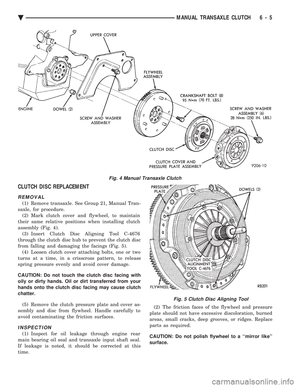
saxle, for procedure. (2) Mark clutch cover and flywheel, to maintain
their same relative positions when installing clutch
assembly (Fig. 4). (3) Insert Clutch Disc Aligning Tool C-4676
through the clutch disc hub to prevent the clutch disc
from falling and damaging the facings (Fig. 5). (4) Loosen clutch cover attaching bolts, one or two
turns at a time, in a crisscross pattern, to release
spring pressure evenly and avoid cover damage.
CAUTION: Do not touch the clutch disc facing with
oily or dirty hands. Oil or dirt transferred from your
hands onto the clutch disc facing may cause clutch
chatter.
(5) Remove the clutch pressure plate and cover as-
sembly and disc from flywheel. Handle carefully to
avoid contaminating the friction surfaces.
INSPECTION
(1) Inspect for oil leakage through engine rear
main bearing oil seal and transaxle input shaft seal.
If leakage is noted, it should be corrected at this
time. (2) The friction faces of the flywheel and pressure
plate should not have excessive discoloration, burned
areas, small cracks, deep grooves, or ridges. Replace
parts as required.
CAUTION: Do not polish flywheel to a ``mirror like''
surface.
Fig. 4 Manual Transaxle Clutch
Fig. 5 Clutch Disc Aligning Tool
Ä MANUAL TRANSAXLE CLUTCH 6 - 5
Page 563 of 2438
CENTER CONSOLE ASSEMBLY REPLACEMENT
(1) Place transmission in neutral and remove
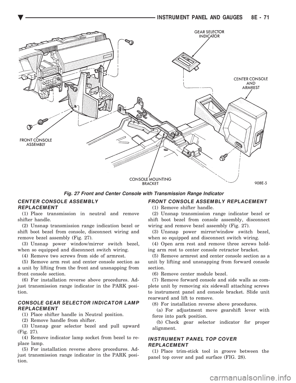
shifter handle. (2) Unsnap transmission range indication bezel or
shift boot bezel from console, disconnect wiring and
remove bezel assembly (Fig. 27). (3) Unsnap power window/mirror switch bezel,
when so equipped and disconnect switch wiring. (4) Remove two screws from side of armrest.
(5) Remove arm rest and center console section as
a unit by lifting from the front and unsnapping from
front console section. (6) For installation reverse above procedures. Ad-
just transmission range indicator in the PARK posi-
tion.
CONSOLE GEAR SELECTOR INDICATOR LAMP REPLACEMENT
(1) Place shifter handle in Neutral position.
(2) Remove handle from shifter.
(3) Unsnap gear selector bezel and pull upward
(Fig. 27). (4) Remove indicator lamp socket from bezel to re-
place lamp. (5) For installation reverse above procedures. Ad-
just transmission range indicator in the PARK posi-
tion.
FRONT CONSOLE ASSEMBLY REPLACEMENT
(1) Remove shifter handle.
(2) Unsnap transmission range indicator bezel or
shift boot bezel from console assembly, disconnect
wiring and remove bezel assembly (Fig. 27). (3) Unsnap power mirror/window switch bezel,
when so equipped and disconnect switch wiring. (4) Open arm rest and remove three screws hold-
ing arm rest to center console retractor bracket. (5) Remove armrest and center console section as a
unit by lifting and unsnapping from forward console
section. (6) Remove center module bezel.
(7) Remove forward console and side walls as com-
plete unit by removing six sidewall attaching screws
to instrument panel and console bracket. Slide unit
rearward and lift to remove. (8) For installation reverse above procedures.(a) For adjustment move gearshift lever with
force into park position. (b) Check gear selector indicator for proper
alignment.
INSTRUMENT PANEL TOP COVER REPLACEMENT
(1) Place trim-stick tool in groove between the
panel top cover and pad surface (FIG. 28).
Fig. 27 Front and Center Console with Transmission Range Indicator
Ä INSTRUMENT PANEL AND GAUGES 8E - 71
Page 681 of 2438
AA .............................................................................74
Low Fuel
AA ...........................................................................103
AP ............................................................................161
AC, AY...............................................................PC194
AG, AJ ............................................................5269245
Low Washer Fluid
AA, AC, AY .............................................................74
AP ............................................................................161
AG, AJ ............................................................4437661
Oil Pressure
All .......................................................................PC194
Trunk Open
AA, AC, AY .............................................................74
AP ............................................................................161
AG, AJ ............................................................4437661
Theft Alarm Set
AC, AY....................................................................168
AG, AJ ............................................................4437661
Turn Signal (MIC)
AA ...........................................................................103
AC, AG, AJ, AP, AY .......................................PC194
Turn Signal (EIC)
AA, AY ..............................................................PC194
Seat Belt (MIC)
AA ...........................................................................103
AC, AG, AJ, AP, AY .......................................PC194
Seat Belt (EIC)
AA, AY ..............................................................PC194
AJ ............................................................................103
DIMMER CONTROLLED LAMPS
Service procedures for most of the lamps in the in-
strument panel, Instrument cluster and switches are
located in Group 8E, Instrument Panel and Gauges. A/C Heater Control
All ..............................................................................37
Automatic Temperature Control
All ....................................................................4437661
Column Gearshift Indicator
AA, AC, AY ...........................................................161
Console Gearshift Indicator
AP ............................................................................194
AA, AG, AJ ............................................................161
Fog Lamp Switch Symbol
AG ......................................................................PC194
Headlamp Dimmer Switch
AG, AJ ......................................................................37
Headlamp Switch Symbol
AC, AY....................................................................161
AG, AJ ......................................................................37
Heater Control
All ............................................................................158
EVIC
AJ...........................................................................ASC
Instrument Cluster (MIC)
All .......................................................................PC194
Instrument Cluster (EIC) AA, AY .....................................................................74
Message Center
AA, AC, AY .............................................................74
AP ............................................................................161
Navigator/Travel Companion
AA, AJ ......................................................................74
Radio
All ..........................................................................ASC
Rear Defogger Switch
Not Serviceable, Replace Switch
Rear Wiper Switch
AG .............................................................................37
Theft Alarm
AC, AY....................................................................161
Top Lift Switch
AJ ....................................................................5268053
Travel Computer
All ..........................................................................ASC
Turbo Gauge
AP ............................................................................161
Windshield Wiper Switch
AG, AJ ......................................................................37
NON-DIMMING LAMPS
Service procedures for most of the lamps in the fol-
lowing list can be found in Group 23, Body. Some
components have lamps that can only be serviced by
a Authorized Service Center (ASC) after the compo-
nent is removed from the vehicle. Contact local
dealer for location of nearest ASC. Ash Receiver
AA .............................................................................74
AC, AP, AY ............................................................161
AG, AJ ......................................................................37
Center Console Rear
AJ ............................................................................906
Cigar Lighter
AA, AP ....................................................................161
Courtesy
AA, AC, AY-S .....................................................214-2
AJ ............................................................................906
AY-P.....................................................................212-2
Dome
ALL ......................................................................211-2
Engine Compartment
All ............................................................................105
Glove Compartment
All ..........................................................................1891
Ignition Lock
All ..............................................................................37
Inside Rear View Mirror
AJ ............................................................................168
Overhead Console
AA ...........................................................................912
AC, AY....................................................................906
AG, AJ, AP .........................................................212-2
Reading Lamp Front
All ............................................................................906
Ä LAMPS 8L - 39
Page 707 of 2438
POWER SEATS
CONTENTS
page page
ADJUSTER ............................. 3
CIRCUIT BREAKER TEST .................. 1
ENTHUSIAST SEAT ....................... 4
GENERAL INFORMATION .................. 1
HARNESS VOLTAGE TEST ................. 1
HORIZONTAL AND VERTICAL TRANSMISSIONS ....................... 3
MEMORY CONTROL MODULE REPLACEMENT ....................... 19
MOTOR ................................ 3
MOTOR TESTS .......................... 1
POWER MEMORY SEAT, RECLINER AND MIRRORS ............................. 5 POWER MEMORY SEAT, RECLINER AND
MIRRORS DIAGNOSIS ................... 9
POWER RECLINER MECHANISM ........... 18
POWER RECLINER MOTOR AND CABLE ..... 17
RECLINER SWITCH REPLACEMENT ......... 19
RECLINER SWITCH TEST ................. 19
SEAT ASSEMBLY ........................ 3
SWITCH REPLACEMENT REMOVAL .......... 5
SWITCH TEST ........................... 5
SWITCH TEST ........................... 3
TEST PROCEDURES ...................... 6
TEST PROCEDURES ...................... 1
GENERAL INFORMATION
Power seats can be adjusted in six different direc-
tions up, down, forward, back, tilt forward, or tilt
rearward. A three armature permanent magnet reversible mo-
tor is coupled through cables to worm gear box assem-
blies located in the seat tracks, providing the various
seat movements. The electrical circuit is protected by a 30 amp circuit
breaker located on the fuse block.
TEST PROCEDURES
Before any testing is attempted the battery should be
carefully charged and all connections and terminals
cleaned and tightened to insure proper continuity and
grounds. With dome lamp on, apply switch in direction of
failure. If dome lamp dims the seat motor is trying to
work indicating mechanical jamming. If dome lamp
does not dim, then proceed with the following electrical
tests.
CIRCUIT BREAKER TEST
Find correct circuit breaker on fuse block. Pull out
slightly but be sure that circuit breaker terminals still
contact terminals in fuse block. Connect ground wire of
voltmeter to a good ground. With probe of voltmeter
positive wire, check both terminals of circuit breaker
for battery voltage. If only one terminal checks at
battery voltage, circuit breaker is defective and must
be replaced. If neither terminal shows battery voltage,
check for open or shorted circuit to circuit breaker.
HARNESS VOLTAGE TEST
The following test will determine whether or not
voltage is continuous through the body harness to the
switch. (1) Remove power seat switch from mounting posi-
tion and disconnect switch from wiring harness. (2) Connect one lead of test light to ground terminal,
black wire (BK) of center section, and touch other test
light lead to red wire (RD) terminal. (3) If test light comes on, harness to switch is good.
If test light does not come on, perform circuit breaker
test.
MOTOR TESTS
AA BODY
(1) Remove switch from mounting position and dis-
connect from harness. (2) To check the center motor, connect a jumper wire
between pin 5 and pin 3 (Fig. 1). Connect a second
jumper wire between pin 7 and pin 4 If motor does not
operate, reverse the jumpers, pin 5 to pin 4 and pin 7 to
pin 3. If motor still does not operate check wiring
between switch connector and motor assembly. If wir-
ing checks good replace motor assembly. (3) To check the front motor, connect a jumper wire
between pin 5 and pin 1 (Fig. 1). Connect a second
jumper wire between pin 7 and pin 8. If motor does not
operate, reverse the jumpers, pin 5 to pin 8 and pin 7 to
pin 1. If motor still does not operate check wiring
between switch connector and motor assembly. If wir-
ing checks good replace motor assembly.
(4) To check the rear motor, connect a covered jumper
wire between pin 5 and pin 6 (Fig. 1). Connect a second
Ä POWER SEATS 8R - 1
Page 708 of 2438
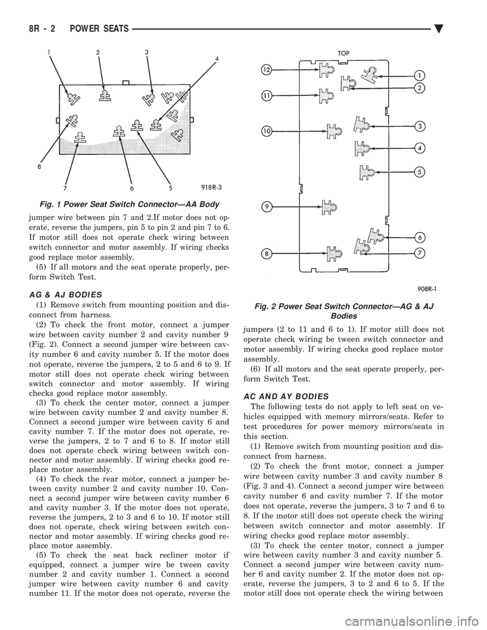
jumper wire between pin 7 and 2.If motor does not op-
erate, reverse the jumpers, pin 5 to pin 2 and pin 7 to 6.
If motor still does not operate check wiring between
switch connector and motor assembly. If wiring checks
good replace motor assembly.
(5) If all motors and the seat operate properly, per-
form Switch Test.
AG & AJ BODIES
(1) Remove switch from mounting position and dis-
connect from harness. (2) To check the front motor, connect a jumper
wire between cavity number 2 and cavity number 9
(Fig. 2). Connect a second jumper wire between cav-
ity number 6 and cavity number 5. If the motor does
not operate, reverse the jumpers, 2 to 5 and 6 to 9. If
motor still does not operate check wiring between
switch connector and motor assembly. If wiring
checks good replace motor assembly. (3) To check the center motor, connect a jumper
wire between cavity number 2 and cavity number 8.
Connect a second jumper wire between cavity 6 and
cavity number 7. If the motor does not operate, re-
verse the jumpers, 2 to 7 and 6 to 8. If motor still
does not operate check wiring between switch con-
nector and motor assembly. If wiring checks good re-
place motor assembly. (4) To check the rear motor, connect a jumper be-
tween cavity number 2 and cavity number 10. Con-
nect a second jumper wire between cavity number 6
and cavity number 3. If the motor does not operate,
reverse the jumpers, 2 to 3 and 6 to 10. If motor still
does not operate, check wiring between switch con-
nector and motor assembly. If wiring checks good re-
place motor assembly. (5) To check the seat back recliner motor if
equipped, connect a jumper wire be tween cavity
number 2 and cavity number 1. Connect a second
jumper wire between cavity number 6 and cavity
number 11. If the motor does not operate, reverse the jumpers (2 to 11 and 6 to 1). If motor still does not
operate check wiring be tween switch connector and
motor assembly. If wiring checks good replace motor
assembly.
(6) If all motors and the seat operate properly, per-
form Switch Test.
AC AND AY BODIES
The following tests do not apply to left seat on ve-
hicles equipped with memory mirrors/seats. Refer to
test procedures for power memory mirrors/seats in
this section. (1) Remove switch from mounting position and dis-
connect from harness. (2) To check the front motor, connect a jumper
wire between cavity number 3 and cavity number 8
(Fig. 3 and 4). Connect a second jumper wire between
cavity number 6 and cavity number 7. If the motor
does not operate, reverse the jumpers, 3 to 7 and 6 to
8. If the motor still does not operate check the wiring
between switch connector and motor assembly. If
wiring checks good replace motor assembly. (3) To check the center motor, connect a jumper
wire between cavity number 3 and cavity number 5.
Connect a second jumper wire between cavity num-
ber 6 and cavity number 2. If the motor does not op-
erate, reverse the jumpers, 3 to 2 and 6 to 5. If the
motor still does not operate check the wiring between
Fig. 1 Power Seat Switch ConnectorÐAA Body
Fig. 2 Power Seat Switch ConnectorÐAG & AJ Bodies
8R - 2 POWER SEATS Ä
Page 711 of 2438
wing. Refer to Owner Manual supplied with vehicle
for complete instructions for seat operation.
SWITCH TEST
For switch testing, remove switch from its mount-
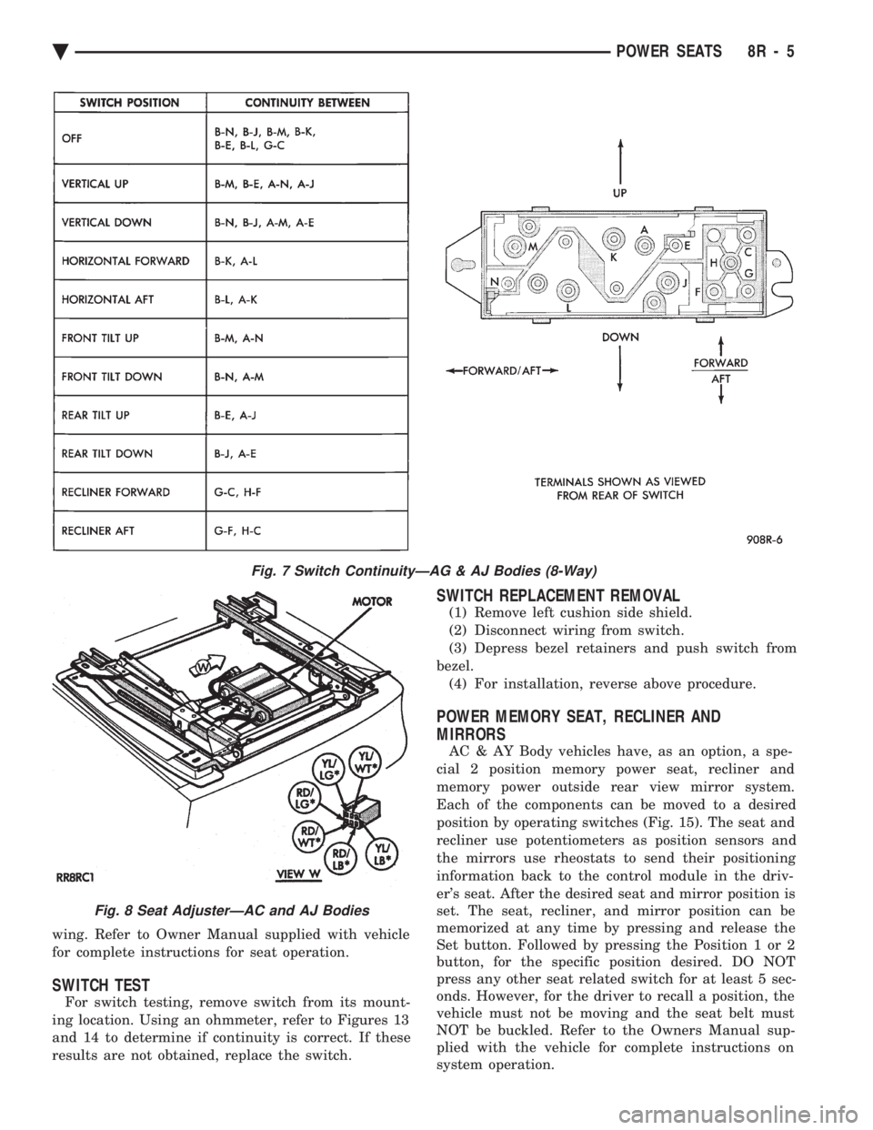
ing location. Using an ohmmeter, refer to Figures 13
and 14 to determine if continuity is correct. If these
results are not obtained, replace the switch.
SWITCH REPLACEMENT REMOVAL
(1) Remove left cushion side shield.
(2) Disconnect wiring from switch.
(3) Depress bezel retainers and push switch from
bezel. (4) For installation, reverse above procedure.
POWER MEMORY SEAT, RECLINER AND
MIRRORS
AC & AY Body vehicles have, as an option, a spe-
cial 2 position memory power seat, recliner and
memory power outside rear view mirror system.
Each of the components can be moved to a desired
position by operating switches (Fig. 15). The seat and
recliner use potentiometers as position sensors and
the mirrors use rheostats to send their positioning
information back to the control module in the driv-
er's seat. After the desired seat and mirror position is
set. The seat, recliner, and mirror position can be
memorized at any time by pressing and release the
Set button. Followed by pressing the Position 1 or 2
button, for the specific position desired. DO NOT
press any other seat related switch for at least 5 sec-
onds. However, for the driver to recall a position, the
vehicle must not be moving and the seat belt must
NOT be buckled. Refer to the Owners Manual sup-
plied with the vehicle for complete instructions on
system operation.
Fig. 7 Switch ContinuityÐAG & AJ Bodies (8-Way)
Fig. 8 Seat AdjusterÐAC and AJ Bodies
Ä POWER SEATS 8R - 5
Page 712 of 2438
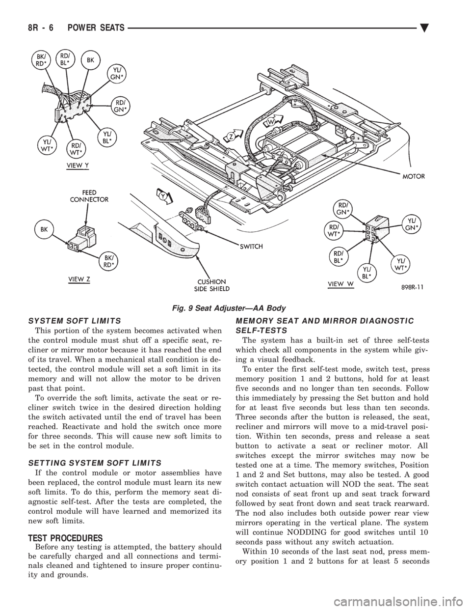
SYSTEM SOFT LIMITS
This portion of the system becomes activated when
the control module must shut off a specific seat, re-
cliner or mirror motor because it has reached the end
of its travel. When a mechanical stall condition is de-
tected, the control module will set a soft limit in its
memory and will not allow the motor to be driven
past that point. To override the soft limits, activate the seat or re-
cliner switch twice in the desired direction holding
the switch activated until the end of travel has been
reached. Reactivate and hold the switch once more
for three seconds. This will cause new soft limits to
be set in the control module.
SETTING SYSTEM SOFT LIMITS
If the control module or motor assemblies have
been replaced, the control module must learn its new
soft limits. To do this, perform the memory seat di-
agnostic self-test. After the tests are completed, the
control module will have learned and memorized its
new soft limits.
TEST PROCEDURES
Before any testing is attempted, the battery should
be carefully charged and all connections and termi-
nals cleaned and tightened to insure proper continu-
ity and grounds.
MEMORY SEAT AND MIRROR DIAGNOSTIC
SELF-TESTS
The system has a built-in set of three self-tests
which check all components in the system while giv-
ing a visual feedback. To enter the first self-test mode, switch test, press
memory position 1 and 2 buttons, hold for at least
five seconds and no longer than ten seconds. Follow
this immediately by pressing the Set button and hold
for at least five seconds but less than ten seconds.
Three seconds after the button is released, the seat,
recliner and mirrors will move to a mid-travel posi-
tion. Within ten seconds, press and release a seat
button to activate a seat or recliner motor. All
switches except the mirror switches may now be
tested one at a time. The memory switches, Position
1 and 2 and Set buttons, may also be tested. A good
switch contact actuation will NOD the seat. The seat
nod consists of seat front up and seat track forward
followed by seat front down and seat track rearward.
The nod also includes both outside power rear view
mirrors operating in the vertical plane. The system
will continue NODDING for good switches until 10
seconds pass without any switch actuation. Within 10 seconds of the last seat nod, press mem-
ory position 1 and 2 buttons for at least 5 seconds
Fig. 9 Seat AdjusterÐAA Body
8R - 6 POWER SEATS Ä
Page 714 of 2438
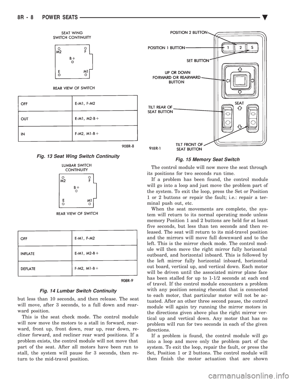
but less than 10 seconds, and then release. The seat
will move, after 3 seconds, to a full down and rear-
ward position. This is the seat check mode. The control module
will now move the motors to a stall in forward, rear-
ward, front up, front down, rear up, rear down, re-
cliner forward, and recliner rear ward positions. If a
problem exists, the control module will not move that
part of the seat. After all motors have been run to
stall, the system will pause for 3 seconds, then re-
turn to the mid-travel position. The control module will now move the seat through
its positions for two seconds run time. If a problem has been found, the control module
will go into a loop and just move the problem part of
the system. To exit the loop, press the Set or Position
1 or 2 buttons or repair the fault; i.e.: repair a ter-
minal push out, etc. When the seat movements are complete, the sys-
tem will return to its normal operating mode unless
memory Position 1 and 2 buttons are held for at least
five seconds, but less than ten seconds and then re-
leased. The seat will return to its mid-travel position
and the mirrors will move full downward and to the
left. This is the mirror check mode. The control mod-
ule will then move the right mirror fully horizontal
outboard, and horizontal inboard. This is followed by
the left mirror fully horizontal inboard, horizontal
out board, vertical up, and vertical down. Each motor
will be driven until the associated mirror plane face
has been stalled for up to 1-1/2 seconds at each end
of travel. If the control module encounters a problem
with any position sensing rheostat that is connected
to each motor, that particular motor will not be ac-
tuated. After an other three second pause, the control
module will again try running the mirror motors in
the directions given above plus the right mirror ver-
tical up and vertical down. Any motor that has no
problem will run for two seconds in each of the given
directions. If a problem is found, the control module will go
into a loop and move only the problem part of the
system. To exit the loop, repair the fault, or press the
Set, Position 1 or 2 buttons. The control module will
then finish the motor actuation that are shown
Fig. 13 Seat Wing Switch Continuity
Fig. 14 Lumbar Switch Continuity
Fig. 15 Memory Seat Switch
8R - 8 POWER SEATS Ä