fuel pump CHEVROLET DYNASTY 1993 Service Manual
[x] Cancel search | Manufacturer: CHEVROLET, Model Year: 1993, Model line: DYNASTY, Model: CHEVROLET DYNASTY 1993Pages: 2438, PDF Size: 74.98 MB
Page 1902 of 2438
3.3L AND 3.8L MULTI-PORT FUEL INJECTIONÐON-BOARD DIAGNOSTICS INDEX
page page
60-Way Pcm Wiring Connector ............. 167
Circuit Actuation Test Mode ................ 166
Diagnostic Trouble Code Description ......... 163
General Information ...................... 162
High and Low Limits ..................... 163
Monitored Circuits ....................... 162 Non-Monitored Circuits
................... 162
State Display Test Mode .................. 163
System Tests .......................... 163
Throttle Body Minimum Air Flow Check Procedure ............................ 166
GENERAL INFORMATION
The powertrain control module (PCM) has been
programmed to monitor many different circuits of the
fuel injection system. If a problem is sensed with a
monitored circuit often enough to indicate an actual
problem, the PCM stores a fault. If the problem is re-
paired or ceases to exist, the PCM cancels the Diag-
nostic trouble code after 51 vehicle key on/off cycles. Certain criteria must be met for a diagnostic trou-
ble code to be entered into the PCM memory. The
criteria may be a specific range of engine RPM, en-
gine temperature, and/or input voltage to the PCM. It is possible a diagnostic trouble code for a moni-
tored circuit may not be entered into memory even
though a malfunction has occurred. This may happen
because one of the diagnostic trouble code criteria for
the circuit has not been met. For example, assume
one of the diagnostic trouble code criteria for a sen-
sor circuit is the engine must be operating between
750 and 2000 RPM. If the sensor output circuit
shorts to ground when engine RPM is above 2400
RPM (resulting i n a 0 volt input to the PCM) a diag-
nostic trouble code will not be entered into memory.
This is because the condition does not occur within
the specified RPM range. There are several operating conditions that the
PCM does not monitor and set diagnostic trouble
codes for. Refer to Monitored Circuits and Non-Mon-
itored Circuits in this section. Stored diagnostic trouble codes can be displayed ei-
ther by cycling the ignition key On - Off - On - Off -
On, or through use of the DRBII scan tool. The
DRBII scan tool connects to the data link connector
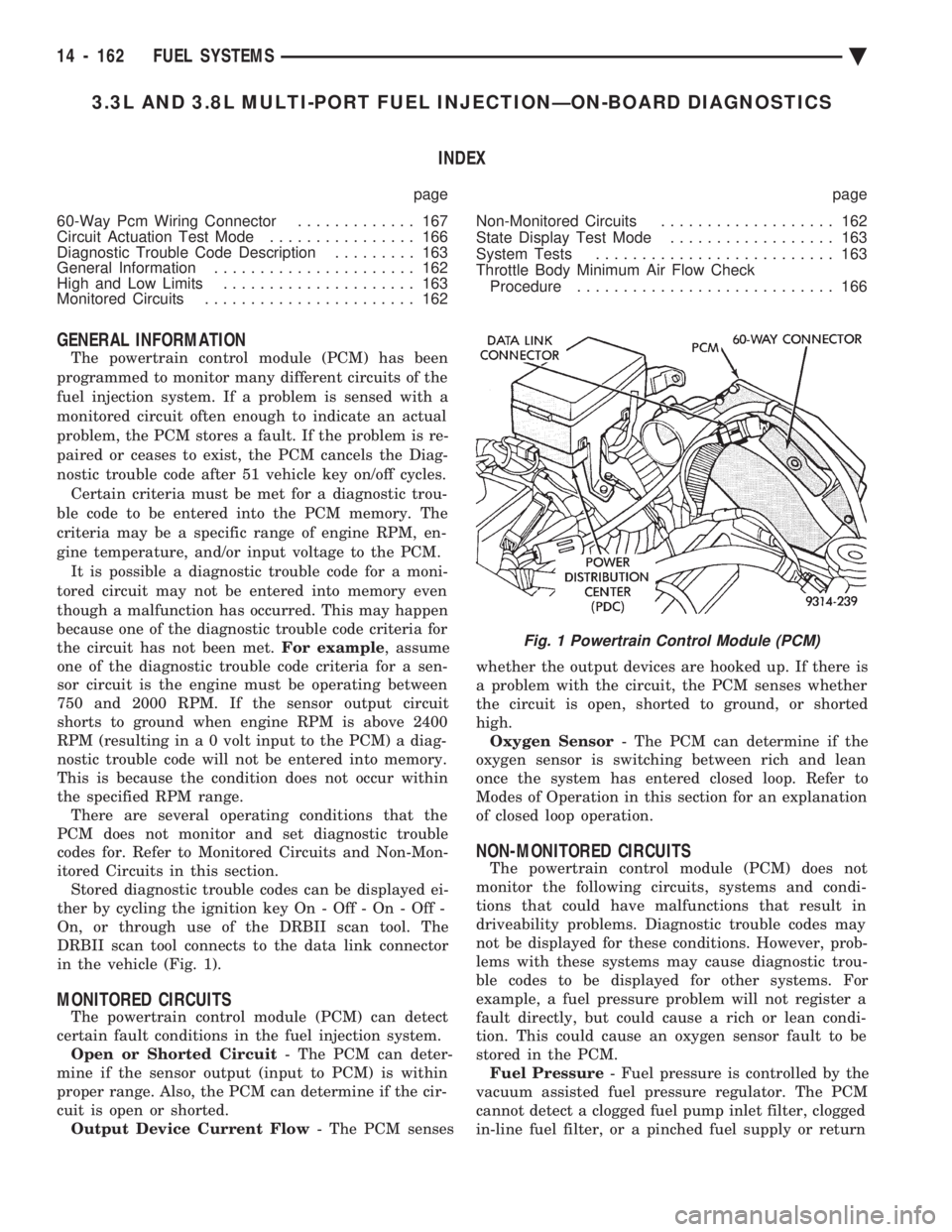
in the vehicle (Fig. 1).
MONITORED CIRCUITS
The powertrain control module (PCM) can detect
certain fault conditions in the fuel injection system. Open or Shorted Circuit - The PCM can deter-
mine if the sensor output (input to PCM) is within
proper range. Also, the PCM can determine if the cir-
cuit is open or shorted. Output Device Current Flow - The PCM senses whether the output devices are hooked up. If there is
a problem with the circuit, the PCM senses whether
the circuit is open, shorted to ground, or shorted
high. Oxygen Sensor - The PCM can determine if the
oxygen sensor is switching between rich and lean
once the system has entered closed loop. Refer to
Modes of Operation in this section for an explanation
of closed loop operation.
NON-MONITORED CIRCUITS
The powertrain control module (PCM) does not
monitor the following circuits, systems and condi-
tions that could have malfunctions that result in
driveability problems. Diagnostic trouble codes may
not be displayed for these conditions. However, prob-
lems with these systems may cause diagnostic trou-
ble codes to be displayed for other systems. For
example, a fuel pressure problem will not register a
fault directly, but could cause a rich or lean condi-
tion. This could cause an oxygen sensor fault to be
stored in the PCM. Fuel Pressure - Fuel pressure is controlled by the
vacuum assisted fuel pressure regulator. The PCM
cannot detect a clogged fuel pump inlet filter, clogged
in-line fuel filter, or a pinched fuel supply or return
Fig. 1 Powertrain Control Module (PCM)
14 - 162 FUEL SYSTEMS Ä
Page 1909 of 2438
3.3L AND 3.8L MULTI-PORT FUEL INJECTIONÐSERVICE PROCEDURES INDEX
page page
Camshaft Position Sensor Service ........... 176
Crankshaft Position Sensor ................ 176
EVAP Canister Purge Solenoid Service ....... 175
Fuel Injector ........................... 174
Fuel Injector Rail Assembly ................ 170
Fuel Pressure Regulator .................. 173
Fuel System Pressure Release Procedure ..... 169 Heated Oxygen Sensor (O
2Sensor) Service . . . 177
Idle Air Control Motor .................... 170
Manifold Absolute Pressure (MAP) Sensor ..... 175
PCM Service ........................... 175
Throttle Body ........................... 169
Throttle Body Removal ................... 169
Throttle Position Sensor .................. 169
THROTTLE BODY REMOVAL
(1) Disconnect negative battery cable.
(2) Remove the air cleaner to throttle body hose
clamp. Remove the nut holding the air cleaner as-
sembly to the air cleaner bracket. Remove the air
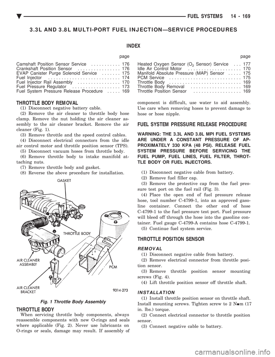
cleaner (Fig. 1). (3) Remove throttle and the speed control cables.
(4) Disconnect electrical connectors from the idle
air control motor and throttle position sensor (TPS). (5) Disconnect vacuum hoses from throttle body.
(6) Remove throttle body to intake manifold at-
taching nuts. (7) Remove throttle body and gasket.
(8) Reverse the above procedure for installation.
THROTTLE BODY
When servicing throttle body components, always
reassemble components with new O-rings and seals
where applicable (Fig. 2). Never use lubricants on
O-rings or seals, damage may result. If assembly of component is difficult, use water to aid assembly.
Use care when removing hoses to prevent damage to
hose or hose nipple.
FUEL SYSTEM PRESSURE RELEASE PROCEDURE
WARNING: THE 3.3L AND 3.8L MPI FUEL SYSTEMS
ARE UNDER A CONSTANT PRESSURE OF AP-
PROXIMATELY 330 KPA (48 PSI). RELEASE FUEL
SYSTEM PRESSURE BEFORE SERVICING THE
FUEL PUMP, FUEL LINES, FUEL FILTER, THROT-
TLE BODY OR FUEL INJECTORS.
(1) Disconnect negative cable from battery.
(2) Remove fuel filler cap.
(3) Remove the protective cap from the fuel pres-
sure test port on the fuel rail (Fig. 3). (4) Place the open end of fuel pressure release
hose, tool number C-4799-1, into an approved gaso-
line container. Connect the other end of hose
C-4799-1 to the fuel pressure test port. Fuel pressure
will bleed off through the hose into the gasoline con-
tainer. Fuel gauge C-4799-A contains hose C-4799-1. (5) Continue fuel system service.
THROTTLE POSITION SENSOR
REMOVAL
(1) Disconnect negative cable from battery.
(2) Remove electrical connector from throttle posi-
tion sensor. (3) Remove throttle position sensor mounting
screws (Fig. 4). (4) Lift throttle position sensor off throttle shaft.
INSTALLATION
(1) Install throttle position sensor on throttle shaft.
Install mounting screws. Tighten screw to 2 N Im (17
in. lbs.) torque. (2) Connect electrical connector to throttle position
sensor. (3) Connect negative cable to battery.Fig. 1 Throttle Body Assembly
Ä FUEL SYSTEMS 14 - 169
Page 2406 of 2438
air entering the outer end of snorkel is 60ÉC (140ÉF.) or
higher, the door should be in the down (heat off)
position. (4) Remove the air cleaner from the engine and
allow it to cool down to 46ÉC (115ÉF). With 20 inches of
vacuum applied to the sensor, the door should be in the
up (heat on position). If the door does not rise to the
heat on position, check the vacuum diaphragm for
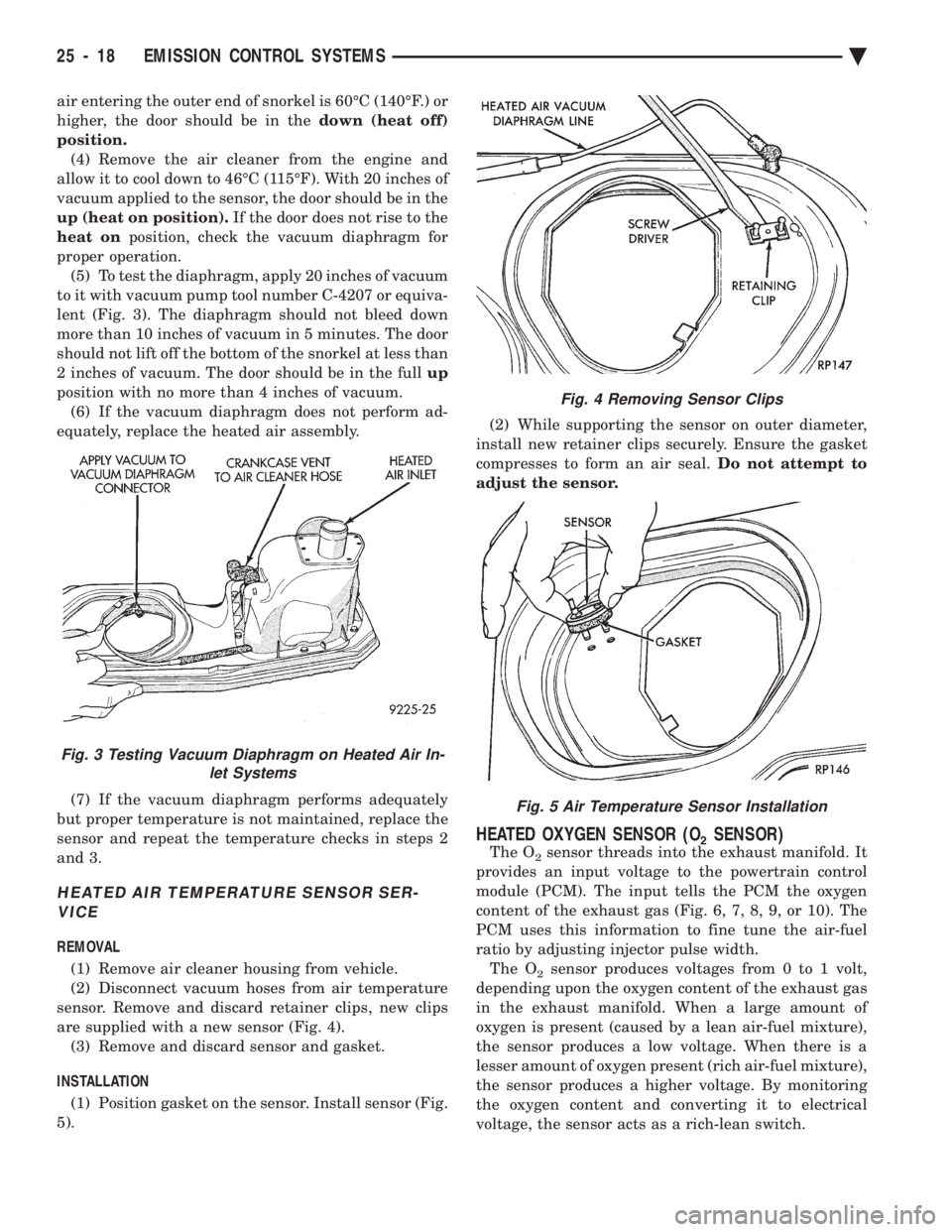
proper operation. (5) To test the diaphragm, apply 20 inches of vacuum
to it with vacuum pump tool number C-4207 or equiva-
lent (Fig. 3). The diaphragm should not bleed down
more than 10 inches of vacuum in 5 minutes. The door
should not lift off the bottom of the snorkel at less than
2 inches of vacuum. The door should be in the full up
position with no more than 4 inches of vacuum. (6) If the vacuum diaphragm does not perform ad-
equately, replace the heated air assembly.
(7) If the vacuum diaphragm performs adequately
but proper temperature is not maintained, replace the
sensor and repeat the temperature checks in steps 2
and 3.
HEATED AIR TEMPERATURE SENSOR SER- VICE
REMOVAL
(1) Remove air cleaner housing from vehicle.
(2) Disconnect vacuum hoses from air temperature
sensor. Remove and discard retainer clips, new clips
are supplied with a new sensor (Fig. 4). (3) Remove and discard sensor and gasket.
INSTALLATION (1) Position gasket on the sensor. Install sensor (Fig.
5). (2) While supporting the sensor on outer diameter,
install new retainer clips securely. Ensure the gasket
compresses to form an air seal. Do not attempt to
adjust the sensor.
HEATED OXYGEN SENSOR (O2SENSOR)
The O2sensor threads into the exhaust manifold. It
provides an input voltage to the powertrain control
module (PCM). The input tells the PCM the oxygen
content of the exhaust gas (Fig. 6, 7, 8, 9, or 10). The
PCM uses this information to fine tune the air-fuel
ratio by adjusting injector pulse width. The O
2sensor produces voltages from 0 to 1 volt,
depending upon the oxygen content of the exhaust gas
in the exhaust manifold. When a large amount of
oxygen is present (caused by a lean air-fuel mixture),
the sensor produces a low voltage. When there is a
lesser amount of oxygen present (rich air-fuel mixture),
the sensor produces a higher voltage. By monitoring
the oxygen content and converting it to electrical
voltage, the sensor acts as a rich-lean switch.
Fig. 3 Testing Vacuum Diaphragm on Heated Air In- let Systems
Fig. 4 Removing Sensor Clips
Fig. 5 Air Temperature Sensor Installation
25 - 18 EMISSION CONTROL SYSTEMS Ä
Page 2409 of 2438
These systems do not allow EGR at idle. The 2.2L/
2.5L EGR systems operate at all temperatures. The
3.0L, 3.3L and 3.8L EGR systems do not operate
when coolant temperature is below 4.5ÉC (40É)F at
start-up. These systems activate when coolant tem-
perature reaches 77ÉC (170ÉF).
EGR SYSTEM ON-BOARD DIAGNOSTICS
The powertrain control module (PCM) performs an
on-board diagnostic check of the EGR system on all
California vehicles with EGR systems. The diagnos-
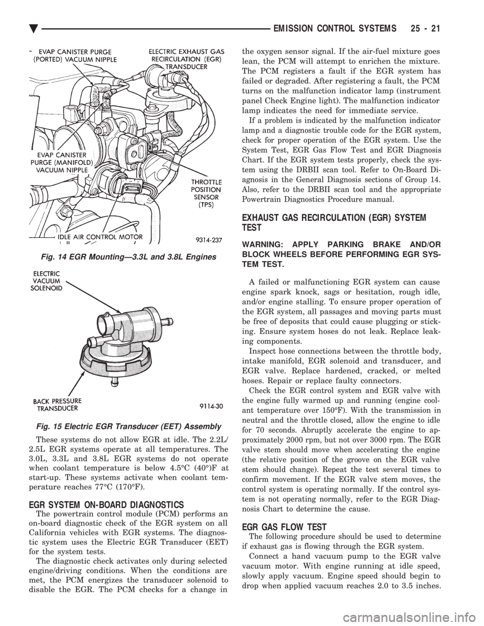
tic system uses the Electric EGR Transducer (EET)
for the system tests. The diagnostic check activates only during selected
engine/driving conditions. When the conditions are
met, the PCM energizes the transducer solenoid to
disable the EGR. The PCM checks for a change in the oxygen sensor signal. If the air-fuel mixture goes
lean, the PCM will attempt to enrichen the mixture.
The PCM registers a fault if the EGR system has
failed or degraded. After registering a fault, the PCM
turns on the malfunction indicator lamp (instrument
panel Check Engine light). The malfunction indicator
lamp indicates the need for immediate service.
If a problem is indicated by the malfunction indicator
lamp and a diagnostic trouble code for the EGR system,
check for proper operation of the EGR system. Use the
System Test, EGR Gas Flow Test and EGR Diagnosis
Chart. If the EGR system tests properly, check the sys-
tem using the DRBII scan tool. Refer to On-Board Di-
agnosis in the General Diagnosis sections of Group 14.
Also, refer to the DRBII scan tool and the appropriate
Powertrain Diagnostics Procedure manual.
EXHAUST GAS RECIRCULATION (EGR) SYSTEM
TEST
WARNING: APPLY PARKING BRAKE AND/OR
BLOCK WHEELS BEFORE PERFORMING EGR SYS-
TEM TEST.
A failed or malfunctioning EGR system can cause
engine spark knock, sags or hesitation, rough idle,
and/or engine stalling. To ensure proper operation of
the EGR system, all passages and moving parts must
be free of deposits that could cause plugging or stick-
ing. Ensure system hoses do not leak. Replace leak-
ing components. Inspect hose connections between the throttle body,
intake manifold, EGR solenoid and transducer, and
EGR valve. Replace hardened, cracked, or melted
hoses. Repair or replace faulty connectors.
Check the EGR control system and EGR valve with
the engine fully warmed up and running (engine cool-
ant temperature over 150ÉF). With the transmission in
neutral and the throttle closed, allow the engine to idle
for 70 seconds. Abruptly accelerate the engine to ap-
proximately 2000 rpm, but not over 3000 rpm. The EGR
valve stem should move when accelerating the engine
(the relative position of the groove on the EGR valve
stem should change). Repeat the test several times to
confirm movement. If the EGR valve stem moves, the
control system is operating normally. If the control sys-
tem is not operating normally, refer to the EGR Diag-
nosis Chart to determine the cause.
EGR GAS FLOW TEST
The following procedure should be used to determine
if exhaust gas is flowing through the EGR system.
Connect a hand vacuum pump to the EGR valve
vacuum motor. With engine running at idle speed,
slowly apply vacuum. Engine speed should begin to
drop when applied vacuum reaches 2.0 to 3.5 inches.
Fig. 14 EGR MountingÐ3.3L and 3.8L Engines
Fig. 15 Electric EGR Transducer (EET) Assembly
Ä EMISSION CONTROL SYSTEMS 25 - 21