fuel pump CHEVROLET DYNASTY 1993 Manual PDF
[x] Cancel search | Manufacturer: CHEVROLET, Model Year: 1993, Model line: DYNASTY, Model: CHEVROLET DYNASTY 1993Pages: 2438, PDF Size: 74.98 MB
Page 1823 of 2438
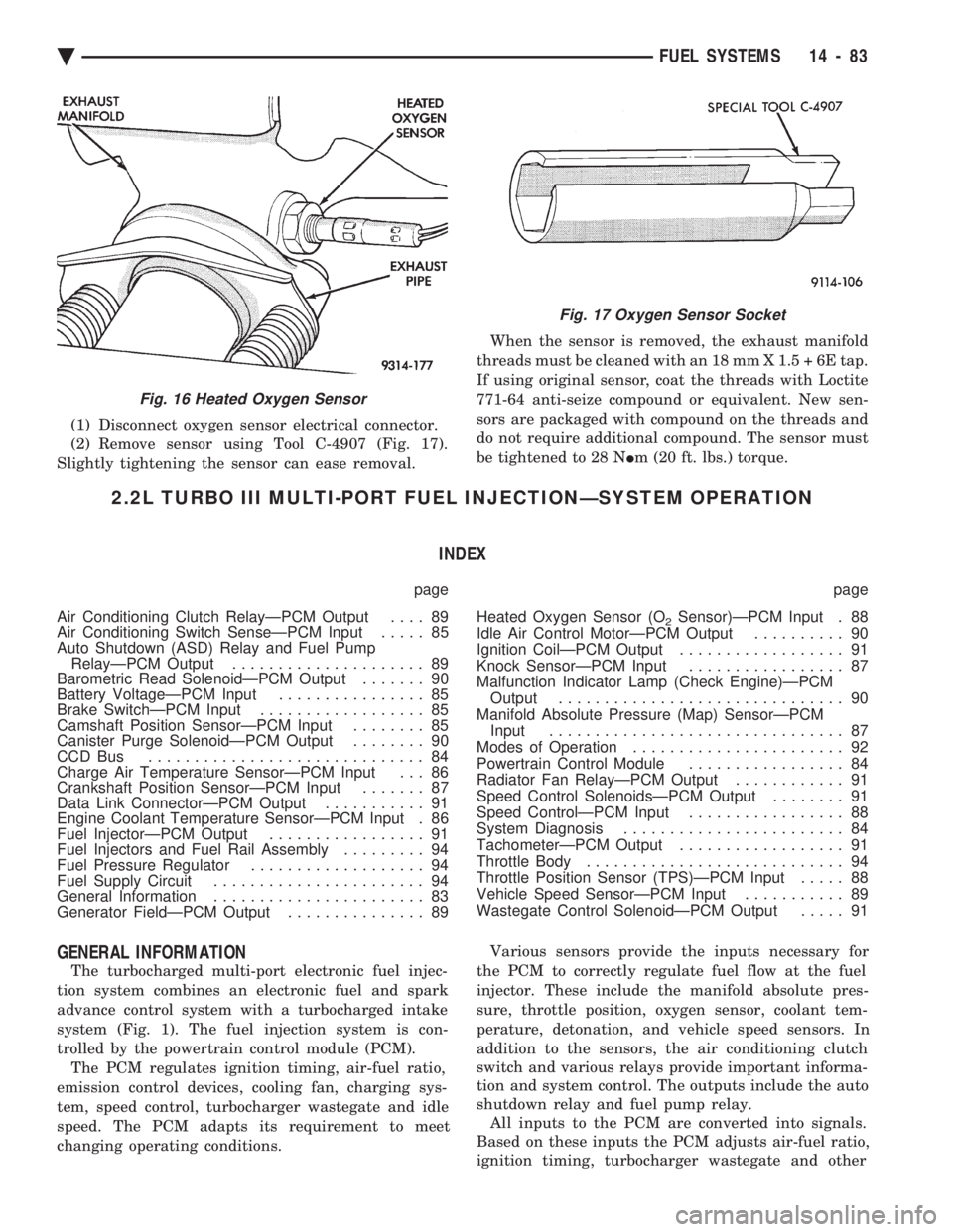
(1) Disconnect oxygen sensor electrical connector.
(2) Remove sensor using Tool C-4907 (Fig. 17).
Slightly tightening the sensor can ease removal. When the sensor is removed, the exhaust manifold
threads must be cleaned with an 18 mm X 1.5 + 6E tap.
If using original sensor, coat the threads with Loctite
771-64 anti-seize compound or equivalent. New sen-
sors are packaged with compound on the threads and
do not require additional compound. The sensor must
be tightened to 28 N Im (20 ft. lbs.) torque.
2.2L TURBO III MULTI-PORT FUEL INJECTIONÐSYSTEM OPERATION
INDEX
page page
Air Conditioning Clutch RelayÐPCM Output .... 89
Air Conditioning Switch SenseÐPCM Input ..... 85
Auto Shutdown (ASD) Relay and Fuel Pump RelayÐPCM Output ..................... 89
Barometric Read SolenoidÐPCM Output ....... 90
Battery VoltageÐPCM Input ................ 85
Brake SwitchÐPCM Input .................. 85
Camshaft Position SensorÐPCM Input ........ 85
Canister Purge SolenoidÐPCM Output ........ 90
CCD Bus .............................. 84
Charge Air Temperature SensorÐPCM Input . . . 86
Crankshaft Position SensorÐPCM Input ....... 87
Data Link ConnectorÐPCM Output ........... 91
Engine Coolant Temperature SensorÐPCM Input . 86
Fuel InjectorÐPCM Output ................. 91
Fuel Injectors and Fuel Rail Assembly ......... 94
Fuel Pressure Regulator ................... 94
Fuel Supply Circuit ....................... 94
General Information ....................... 83
Generator FieldÐPCM Output ............... 89 Heated Oxygen Sensor (O
2Sensor)ÐPCM Input . 88
Idle Air Control MotorÐPCM Output .......... 90
Ignition CoilÐPCM Output .................. 91
Knock SensorÐPCM Input ................. 87
Malfunction Indicator Lamp (Check Engine)ÐPCM Output ............................... 90
Manifold Absolute Pressure (Map) SensorÐPCM Input ................................ 87
Modes of Operation ....................... 92
Powertrain Control Module ................. 84
Radiator Fan RelayÐPCM Output ............ 91
Speed Control SolenoidsÐPCM Output ........ 91
Speed ControlÐPCM Input ................. 88
System Diagnosis ........................ 84
TachometerÐPCM Output .................. 91
Throttle Body ............................ 94
Throttle Position Sensor (TPS)ÐPCM Input ..... 88
Vehicle Speed SensorÐPCM Input ........... 89
Wastegate Control SolenoidÐPCM Output ..... 91
GENERAL INFORMATION
The turbocharged multi-port electronic fuel injec-
tion system combines an electronic fuel and spark
advance control system with a turbocharged intake
system (Fig. 1). The fuel injection system is con-
trolled by the powertrain control module (PCM). The PCM regulates ignition timing, air-fuel ratio,
emission control devices, cooling fan, charging sys-
tem, speed control, turbocharger wastegate and idle
speed. The PCM adapts its requirement to meet
changing operating conditions. Various sensors provide the inputs necessary for
the PCM to correctly regulate fuel flow at the fuel
injector. These include the manifold absolute pres-
sure, throttle position, oxygen sensor, coolant tem-
perature, detonation, and vehicle speed sensors. In
addition to the sensors, the air conditioning clutch
switch and various relays provide important informa-
tion and system control. The outputs include the auto
shutdown relay and fuel pump relay. All inputs to the PCM are converted into signals.
Based on these inputs the PCM adjusts air-fuel ratio,
ignition timing, turbocharger wastegate and other
Fig. 16 Heated Oxygen Sensor
Fig. 17 Oxygen Sensor Socket
Ä FUEL SYSTEMS 14 - 83
Page 1825 of 2438
² Manifold Absolute Pressure (MAP) Sensor
² Oxygen Sensor
² SCI Receive
² Speed Control System Controls
² Throttle Position Sensor
² Vehicle Speed Sensor
PCM Outputs:
² Air Conditioning Clutch Relay
² Generator Field
² Idle Air Control Motor
² Auto Shutdown (ASD) Relay
² Barometric Read Solenoid
² Canister Purge Solenoid
² Malfunction Indicator Lamp (Check Engine Lamp)
² Data Link Connector
² Fuel Injectors
² Ignition Coil
² Radiator Fan Relay
² Speed Control Solenoids
² Tachometer Output
² Wastegate Solenoid
Based on inputs it receives, the PCM adjusts fuel
injector pulse width, idle speed, ignition spark ad-
vance, ignition coil dwell and canister purge opera-
tion. The PCM regulates operation of the cooling fan,
A/C and speed control systems. The PCM changes
generator charge rate by adjusting the generator
field. The PCM adjusts injector pulse width (air-fuel ra-
tio) based on the following inputs.
² battery voltage
² engine coolant temperature
² exhaust gas content
² engine speed (crankshaft position sensor)
² manifold absolute pressure
² throttle position
The PCM adjusts ignition timing based on the fol-
lowing inputs.
² engine coolant temperature
² knock sensor
² engine speed (crankshaft position sensor)
² manifold absolute pressure
² throttle position
The Automatic Shut Down (ASD) and Fuel Pump
relays are mounted externally, but turned on and off
by the PCM through the same circuit. The camshaft position sensor and crankshaft posi-
tion sensor signals are sent to the PCM. If the PCM
does not receive both signals within approximately
one second of engine cranking, it deactivates the
ASD relay and fuel pump relay. When these relays
are deactivated, power is shut off to the fuel injector,
ignition coil, oxygen sensor heating element and fuel
pump. The PCM contains a voltage converter that
changes battery voltage to a regulated 8.0 volts. The
8.0 volts power the camshaft position sensor, crank- shaft position sensor and vehicle speed sensor. The
PCM also provides a 5.0 volts supply for the coolant
temperature sensor, manifold absolute pressure sen-
sor and throttle position sensor.
AIR CONDITIONING SWITCH SENSEÐPCM INPUT
When the air conditioning or defrost switch is put
in the ON position and the low pressure and high
pressure switches are closed, the PCM receives an in-
put for air conditioning. After receiving this input,
the PCM activates the A/C compressor clutch by
grounding the A/C clutch relay. The PCM also ad-
justs idle speed to a scheduled RPM to compensate
for increased engine load.
BATTERY VOLTAGEÐPCM INPUT
The PCM monitors the battery voltage input to de-
termine fuel injector pulse width and generator field
control. If battery voltage is low the PCM will in-
crease injector pulse width (period of time that the
injector is energized).
BRAKE SWITCHÐPCM INPUT
When the brake switch is activated, the PCM re-
ceives an input indicating that the brakes are being
applied. After receiving this input, the PCM vents
the speed control servo. Venting the servo turns the
speed control system off. The brake switch is
mounted on the brake pedal support bracket.
CAMSHAFT POSITION SENSORÐPCM INPUT
Fuel injection synchronization and cylinder identi-
fication are provided through the camshaft position
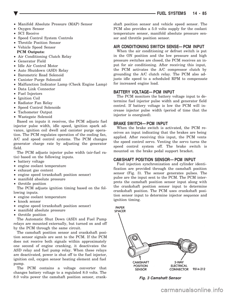
sensor (Fig. 3). The sensor generates pulses. The
pulse are the input sent to the PCM. The PCM inter-
prets the camshaft position sensor input along with
the crankshaft position sensor input to determine
crankshaft position. The PCM uses crankshaft posi-
tion sensor input to determine injector sequence and
ignition timing.
Fig. 3 Camshaft Sensor
Ä FUEL SYSTEMS 14 - 85
Page 1829 of 2438
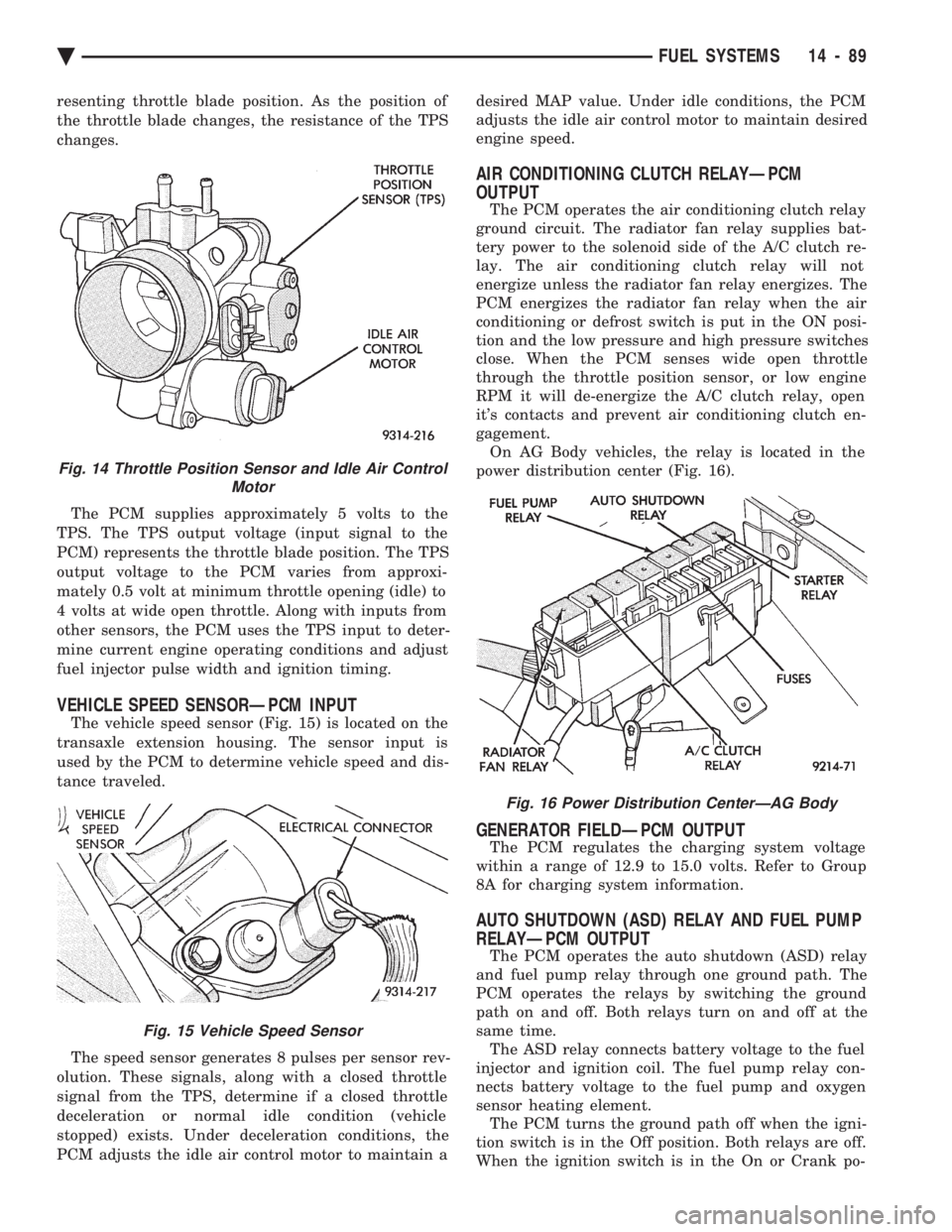
resenting throttle blade position. As the position of
the throttle blade changes, the resistance of the TPS
changes. The PCM supplies approximately 5 volts to the
TPS. The TPS output voltage (input signal to the
PCM) represents the throttle blade position. The TPS
output voltage to the PCM varies from approxi-
mately 0.5 volt at minimum throttle opening (idle) to
4 volts at wide open throttle. Along with inputs from
other sensors, the PCM uses the TPS input to deter-
mine current engine operating conditions and adjust
fuel injector pulse width and ignition timing.
VEHICLE SPEED SENSORÐPCM INPUT
The vehicle speed sensor (Fig. 15) is located on the
transaxle extension housing. The sensor input is
used by the PCM to determine vehicle speed and dis-
tance traveled.
The speed sensor generates 8 pulses per sensor rev-
olution. These signals, along with a closed throttle
signal from the TPS, determine if a closed throttle
deceleration or normal idle condition (vehicle
stopped) exists. Under deceleration conditions, the
PCM adjusts the idle air control motor to maintain a desired MAP value. Under idle conditions, the PCM
adjusts the idle air control motor to maintain desired
engine speed.
AIR CONDITIONING CLUTCH RELAYÐPCM
OUTPUT
The PCM operates the air conditioning clutch relay
ground circuit. The radiator fan relay supplies bat-
tery power to the solenoid side of the A/C clutch re-
lay. The air conditioning clutch relay will not
energize unless the radiator fan relay energizes. The
PCM energizes the radiator fan relay when the air
conditioning or defrost switch is put in the ON posi-
tion and the low pressure and high pressure switches
close. When the PCM senses wide open throttle
through the throttle position sensor, or low engine
RPM it will de-energize the A/C clutch relay, open
it's contacts and prevent air conditioning clutch en-
gagement. On AG Body vehicles, the relay is located in the
power distribution center (Fig. 16).
GENERATOR FIELDÐPCM OUTPUT
The PCM regulates the charging system voltage
within a range of 12.9 to 15.0 volts. Refer to Group
8A for charging system information.
AUTO SHUTDOWN (ASD) RELAY AND FUEL PUMP
RELAYÐPCM OUTPUT
The PCM operates the auto shutdown (ASD) relay
and fuel pump relay through one ground path. The
PCM operates the relays by switching the ground
path on and off. Both relays turn on and off at the
same time. The ASD relay connects battery voltage to the fuel
injector and ignition coil. The fuel pump relay con-
nects battery voltage to the fuel pump and oxygen
sensor heating element. The PCM turns the ground path off when the igni-
tion switch is in the Off position. Both relays are off.
When the ignition switch is in the On or Crank po-
Fig. 14 Throttle Position Sensor and Idle Air Control Motor
Fig. 15 Vehicle Speed Sensor
Fig. 16 Power Distribution CenterÐAG Body
Ä FUEL SYSTEMS 14 - 89
Page 1830 of 2438
sition, the PCM monitors the crankshaft position and
camshaft position sensor signals to determine engine
speed and ignition timing (coil dwell). If the PCM
does not receive the crankshaft position sensor and
camshaft position sensor signals when the ignition
switch is in the Run position, it de-energizes both re-
lays. When the relays are de-energized, battery volt-
age is not supplied to the fuel injector, ignition coil,
fuel pump and oxygen sensor heating element. The ASD relay and fuel pump relay are located in
the power distribution center (Fig. 16).
IDLE AIR CONTROL MOTORÐPCM OUTPUT
The idle air control motor is mounted on the throt-
tle body (Fig. 14). The PCM operates the motor. The
PCM adjusts engine idle speed through the idle air
control motor to compensate for engine load or ambi-
ent conditions. The throttle body has an air bypass passage that
provides air for the engine at idle (the throttle blade
is closed). The idle air control motor pintle protrudes
into the air bypass passage and regulates air flow
through it. The PCM adjusts engine idle speed by moving the
idle air control motor pintle in and out of the bypass
passage. The adjustments are based on inputs the
PCM receives. The inputs are from the throttle posi-
tion sensor, camshaft position sensor, crankshaft po-
sition sensor, coolant temperature sensor, and
various switch operations (brake and air condition-
ing). Deceleration die out is also prevented by in-
creasing airflow when the throttle is closed quickly
after a driving (speed) condition.
BAROMETRIC READ SOLENOIDÐPCM OUTPUT
The barometric pressure read solenoid is spliced
into the manifold absolute pressure (MAP) sensor
vacuum hose (Fig. 12). The barometric read solenoid
switches the pressure supply to the MAP sensor from
either barometric pressure (atmospheric) or manifold
vacuum. The PCM operates the solenoid. Atmospheric pressure is periodically supplied to
the MAP sensor to measure barometric pressure.
This occurs at closed throttle, once per throttle clo-
sure but no more often than once every 3 minutes
and within a specified RPM band. Barometric infor-
mation is used primarily for boost control and start
fuel enrichment at various altitudes.
CANISTER PURGE SOLENOIDÐPCM OUTPUT
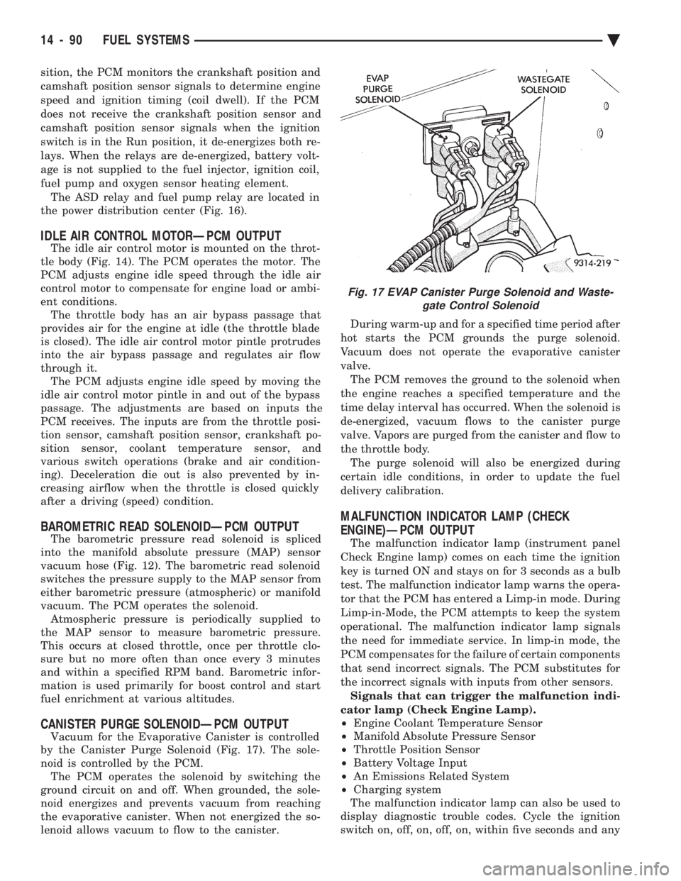
Vacuum for the Evaporative Canister is controlled
by the Canister Purge Solenoid (Fig. 17). The sole-
noid is controlled by the PCM. The PCM operates the solenoid by switching the
ground circuit on and off. When grounded, the sole-
noid energizes and prevents vacuum from reaching
the evaporative canister. When not energized the so-
lenoid allows vacuum to flow to the canister. During warm-up and for a specified time period after
hot starts the PCM grounds the purge solenoid.
Vacuum does not operate the evaporative canister
valve. The PCM removes the ground to the solenoid when
the engine reaches a specified temperature and the
time delay interval has occurred. When the solenoid is
de-energized, vacuum flows to the canister purge
valve. Vapors are purged from the canister and flow to
the throttle body. The purge solenoid will also be energized during
certain idle conditions, in order to update the fuel
delivery calibration.
MALFUNCTION INDICATOR LAMP (CHECK
ENGINE)ÐPCM OUTPUT
The malfunction indicator lamp (instrument panel
Check Engine lamp) comes on each time the ignition
key is turned ON and stays on for 3 seconds as a bulb
test. The malfunction indicator lamp warns the opera-
tor that the PCM has entered a Limp-in mode. During
Limp-in-Mode, the PCM attempts to keep the system
operational. The malfunction indicator lamp signals
the need for immediate service. In limp-in mode, the
PCM compensates for the failure of certain components
that send incorrect signals. The PCM substitutes for
the incorrect signals with inputs from other sensors. Signals that can trigger the malfunction indi-
cator lamp (Check Engine Lamp).
² Engine Coolant Temperature Sensor
² Manifold Absolute Pressure Sensor
² Throttle Position Sensor
² Battery Voltage Input
² An Emissions Related System
² Charging system
The malfunction indicator lamp can also be used to
display diagnostic trouble codes. Cycle the ignition
switch on, off, on, off, on, within five seconds and any
Fig. 17 EVAP Canister Purge Solenoid and Waste- gate Control Solenoid
14 - 90 FUEL SYSTEMS Ä
Page 1831 of 2438
diagnostic trouble codes stored in the PCM will be
displayed. Refer to the 2.2L Turbo III Multi-port Fuel
InjectionÐOn-Board Diagnostics section of this
Group for Diagnostic trouble code Descriptions.
DATA LINK CONNECTORÐPCM OUTPUT
The data link connector provides the technician
with the means to connect the DRBII scan tool to di-
agnosis the vehicle.
FUEL INJECTORÐPCM OUTPUT
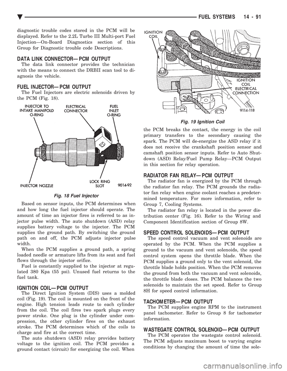
The Fuel Injectors are electric solenoids driven by
the PCM (Fig. 18).
Based on sensor inputs, the PCM determines when
and how long the fuel injector should operate. The
amount of time an injector fires is referred to as in-
jector pulse width. The auto shutdown (ASD) relay
supplies battery voltage to the injector. The PCM
supplies the ground path. By switching the ground
path on and off, the PCM adjusts injector pulse
width. When the PCM supplies a ground path, a spring
loaded needle or armature lifts from its seat and fuel
flows through the injector orifice. Fuel is constantly supplied to the injector at regu-
lated 380 Kpa (55 psi). Unused fuel returns to the
fuel tank.
IGNITION COILÐPCM OUTPUT
The Direct Ignition System (DIS) uses a molded
coil (Fig. 19). The coil is mounted on the front of the
engine. High tension leads route to each cylinder
from the coil. The coil fires two spark plugs every
power stroke. One plug is the cylinder under com-
pression, the other cylinder fires on the exhaust
stroke. The PCM determines which of the coils to
charge and fire at the correct time. The auto shutdown (ASD) relay provides battery
voltage to the ignition coil. The PCM provides a
ground contact (circuit) for energizing the coil. When the PCM breaks the contact, the energy in the coil
primary transfers to the secondary causing the
spark. The PCM will de-energize the ASD relay if it
does not receive the crankshaft position sensor and
camshaft position sensor inputs. Refer to Auto Shut-
down (ASD) Relay/Fuel Pump RelayÐPCM Output
in this section for relay operation.
RADIATOR FAN RELAYÐPCM OUTPUT
The radiator fan is energized by the PCM through
the radiator fan relay. The PCM grounds the radia-
tor fan relay when engine coolant reaches a predeter-
mined temperature. For more information, refer to
Group 7, Cooling Systems. The radiator fan relay is located in the power dis-
tribution center (Fig. 16). Refer to the Wiring and
Component Identification section of Group 8W.
SPEED CONTROL SOLENOIDSÐPCM OUTPUT
The speed control vacuum and vent solenoids are
operated by the PCM. When the PCM supplies a
ground to the vacuum and vent solenoids, the speed
control system opens the throttle blade. When the
PCM supplies a ground only to the vent solenoid, the
throttle blade holds position. When the PCM removes
the ground from both the vacuum and vent solenoids,
the throttle blade closes. The PCM balances the two
solenoids to maintain the set speed. Refer to Group
8H for speed control information.
TACHOMETERÐPCM OUTPUT
The PCM supplies engine RPM to the instrument
panel tachometer. Refer to Group 8 for tachometer
information.
WASTEGATE CONTROL SOLENOIDÐPCM OUTPUT
The PCM operates the wastegate control solenoid.
The PCM adjusts maximum boost to varying engine
conditions by changing the amount of time the sole-
Fig. 18 Fuel Injector
Fig. 19 Ignition Coil
Ä FUEL SYSTEMS 14 - 91
Page 1832 of 2438
noid is energized. The solenoid mounts to the passen-
ger side inner fender panel, next to the strut tower
(Fig. 17).
MODES OF OPERATION
As input signals to the PCM change, the PCM
adjusts its response to the output devices. For example,
the PCM must calculate a different injector pulse
width and ignition timing for idle than it does for wide
open throttle (WOT). There are several different modes
of operation that determine how the PCM responds to
the various input signals. There are two different areas of operation, OPEN
LOOP and CLOSED LOOP. During OPEN LOOP modes, the PCM receives input
signals and responds according to preset PCM pro-
gramming. Input from the oxygen (O
2) sensor is not
monitored during OPEN LOOP modes. During CLOSED LOOP modes, the PCM does moni-
tor the oxygen (O
2) sensor input. This input indicates
to the PCM whether or not the calculated injector pulse
width results in the ideal air-fuel ratio of 14.7 parts air
to 1 part fuel. By monitoring the exhaust oxygen
content through the O
2sensor, the PCM can fine tune
the injector pulse width to achieve optimum fuel
economy combined with low emissions. The 2.2L Turbo III multi-port fuel injection system
has the following modes of operation:
² Ignition switch ON - Zero RPM
² Engine start-up
² Engine warm-up
² Cruise (Idle)
² Acceleration
² Deceleration
² Wide Open Throttle
² Ignition switch OFF
The engine start-up (crank), engine warm-up, and
wide open throttle modes are OPEN LOOP modes. The
acceleration, deceleration, and cruise modes, with the
engine at operating temperature are CLOSED
LOOP modes (under most operating conditions).
IGNITION SWITCH ON (ZERO RPM) MODE
When the ignition switch activates the fuel injection
system the following actions occur:
²
The PCM calculates basic fuel strategy by determining
atmospheric air pressure from the MAP sensor input.
² The PCM monitors the coolant temperature sensor
and throttle position sensor input. The PCM modifies
fuel strategy based on this input. When the key is in the ON position and the engine is
not running, the auto shutdown (ASD) relay and fuel
pump relay are not energized. Therefore battery volt-
age is not supplied to the fuel pump, ignition coil, fuel
injector or oxygen sensor heating element.
ENGINE START-UP MODE
This is an OPEN LOOP mode. The following actions
occur when the starter motor is engaged. If the PCM receives the camshaft position and crank-
shaft position sensor signals, it energizes the auto
shutdown (ASD) relay and fuel pump relay. These
relays supply battery voltage to the fuel pump, fuel
injectors, ignition coil, and oxygen sensor heating ele-
ment. If the PCM does not receive the camshaft posi-
tion sensor and crankshaft position sensor signals
within approximately one second, it de-energizes the
ASD relay and fuel pump relay. The PCM energizes all injectors until it determines
crankshaft position from the camshaft position sensor
and crankshaft position sensor signals. The PCM de-
termines crankshaft position within 1 engine revolu-
tion. After determining crankshaft position, the PCM be-
gins energizing the injectors in sequence. The PCM
adjusts injector pulse width and controls injector syn-
chronization by turning the individual ground paths to
the injectors On and Off. When the engine idles within 664 RPM of its target
RPM, the PCM compares current MAP sensor value
with the atmospheric pressure value received during
the Ignition Switch On (zero RPM) mode. If the PCM
does not detect a minimum difference between the two
values, it sets a MAP fault into memory. Once the ASD and fuel pump relays have been
energized, the PCM:
² Determines injector pulse width based on coolant
temperature, manifold absolute pressure (MAP) and
the number of engine revolutions since cranking was
initiated.
² Monitors the coolant temperature sensor, camshaft
position sensor, crankshaft position sensor, MAP sen-
sor, and throttle position sensor to determine correct
ignition timing.
ENGINE WARM-UP MODE
This is a OPEN LOOP mode. The following inputs
are received by the PCM:
² engine coolant temperature
² knock sensor
² manifold absolute pressure (MAP)
² engine speed (crankshaft position sensor)
² throttle position
² A/C switch
² battery voltage
The PCM provides a ground path for the injectors to
precisely control injector pulse width (by switching the
ground on and off). The PCM adjusts engine idle speed
through the idle air control motor. Also, the PCM
regulates ignition timing.
14 - 92 FUEL SYSTEMS Ä
Page 1834 of 2438
THROTTLE BODY
The throttle body assembly is located on the left
end of the intake manifold plenum (Fig. 20). The
throttle body houses the throttle position sensor and
the idle air control motor. Air flow through the throt-
tle body is controlled by a cable operated throttle
blade located in the base of the throttle body.
FUEL SUPPLY CIRCUIT
Fuel is pumped to the fuel rail by an electrical
pump in the fuel tank. The pump inlet is fitted with
a strainer to prevent water and other contaminants
from entering the fuel supply circuit. Fuel pressure is controlled to a preset level above
intake manifold pressure by a pressure regulator.
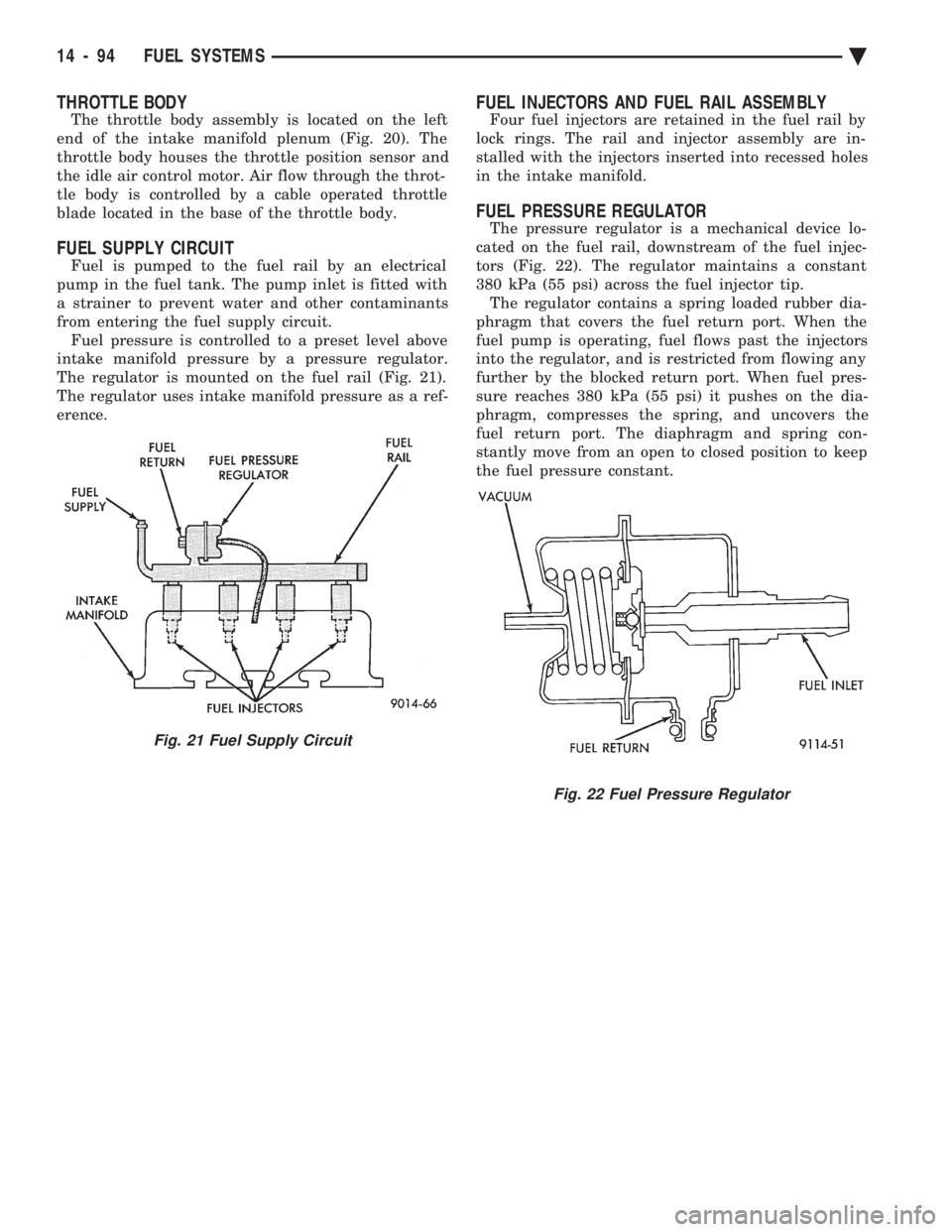
The regulator is mounted on the fuel rail (Fig. 21).
The regulator uses intake manifold pressure as a ref-
erence.
FUEL INJECTORS AND FUEL RAIL ASSEMBLY
Four fuel injectors are retained in the fuel rail by
lock rings. The rail and injector assembly are in-
stalled with the injectors inserted into recessed holes
in the intake manifold.
FUEL PRESSURE REGULATOR
The pressure regulator is a mechanical device lo-
cated on the fuel rail, downstream of the fuel injec-
tors (Fig. 22). The regulator maintains a constant
380 kPa (55 psi) across the fuel injector tip. The regulator contains a spring loaded rubber dia-
phragm that covers the fuel return port. When the
fuel pump is operating, fuel flows past the injectors
into the regulator, and is restricted from flowing any
further by the blocked return port. When fuel pres-
sure reaches 380 kPa (55 psi) it pushes on the dia-
phragm, compresses the spring, and uncovers the
fuel return port. The diaphragm and spring con-
stantly move from an open to closed position to keep
the fuel pressure constant.
Fig. 21 Fuel Supply Circuit
Fig. 22 Fuel Pressure Regulator
14 - 94 FUEL SYSTEMS Ä
Page 1839 of 2438
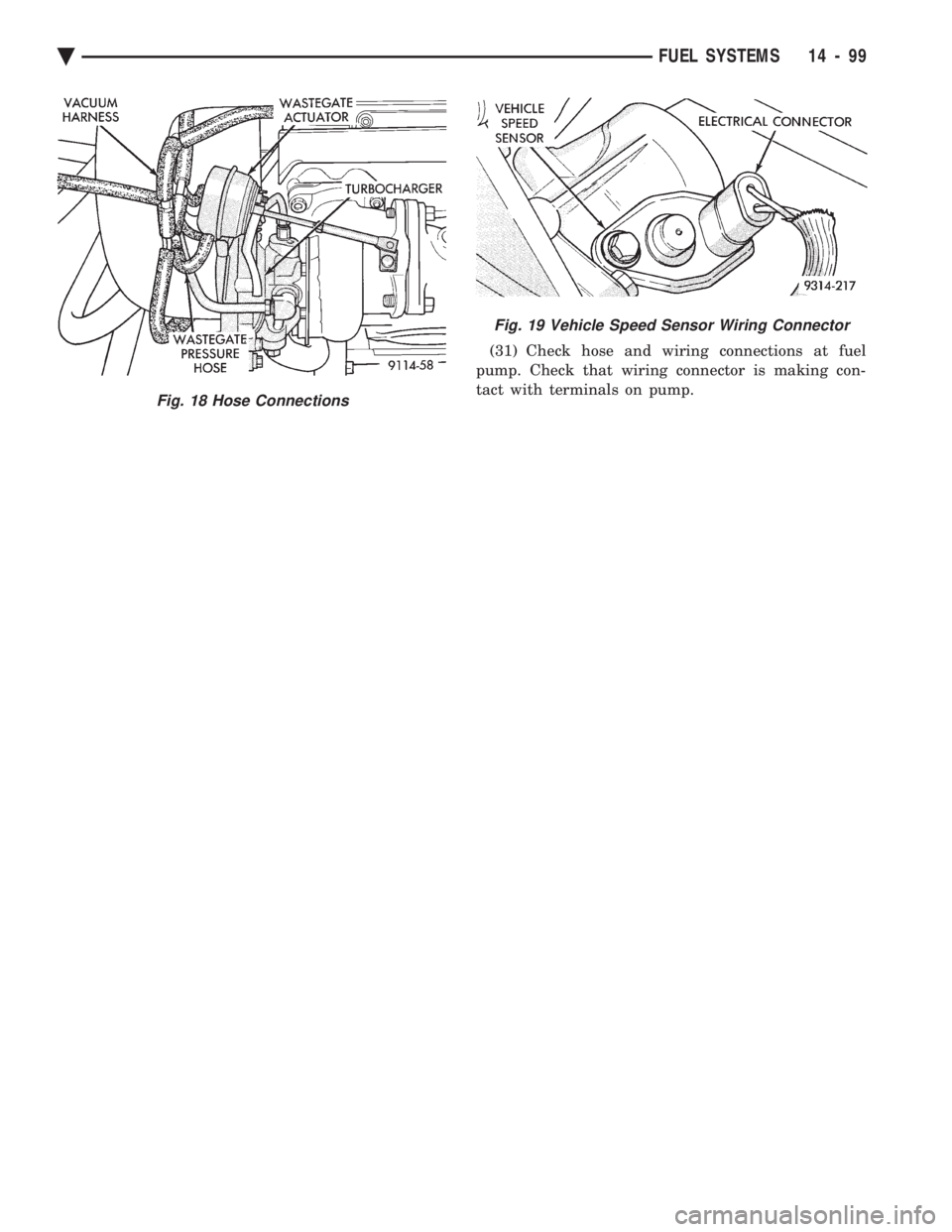
(31) Check hose and wiring connections at fuel
pump. Check that wiring connector is making con-
tact with terminals on pump.
Fig. 18 Hose Connections
Fig. 19 Vehicle Speed Sensor Wiring Connector
Ä FUEL SYSTEMS 14 - 99
Page 1840 of 2438
2.2L TURBO III MULTI-PORT FUEL INJECTIONÐON-BOARD DIAGNOSTICS INDEX
page page
60-Way PCM Wiring Connector ............. 105
Circuit Actuation Test Mode ................ 105
Diagnostic Trouble Code Description ......... 101
General Information ...................... 100
High and Low Limits ..................... 101
Ignition Timing Procedure ................. 105 Monitored Circuits
....................... 100
Non-Monitored Circuits ................... 100
State Display Test Mode .................. 104
System Tests .......................... 104
Throttle Body Minimum Air Flow Check Procedure ............................ 105
GENERAL INFORMATION
The powertrain control module (PCM) has been pro-
grammed to monitor many different circuits of the fuel
injection system. If a problem is sensed with a moni-
tored circuit often enough to indicate an actual prob-
lem, the PCM stores a fault. If the problem is repaired
or ceases to exist, the PCM cancels the Diagnostic
trouble code after 51 vehicle key on/off cycles. Certain criteria must be met for a diagnostic trouble
code to be entered into PCM memory. The criteria may
be a specific range of engine RPM, engine temperature,
and/or input voltage to the PCM. It is possible that a diagnostic trouble code for a
monitored circuit may not be entered into memory
even though a malfunction has occurred. This may
happen because one of the diagnostic trouble code
criteria for the circuit has not been met. For example,
assume that one of the diagnostic trouble code criteria
for a certain sensor circuit is that the engine must be
operating between 750 and 2000 RPM. If the sensor
output circuit shorts to ground when engine RPM is
above 2400 RPM (resulting i n a 0 volt input to the
PCM) a diagnostic trouble code will not be entered into
memory. This is because the condition does not occur
within the specified RPM range. There are several operating conditions for which the
PCM does not monitor and set diagnostic trouble codes.
Refer to Monitored Circuits and Non-Monitored Cir-
cuits in this section. Stored diagnostic trouble codes can be displayed
either by cycling the ignition key On - Off - On - Off -
On, or through use of the DRB II scan tool. The DRBII
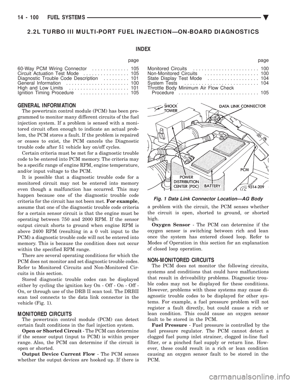
scan tool connects to the data link connector in the
vehicle (Fig. 1).
MONITORED CIRCUITS
The powertrain control module (PCM) can detect
certain fault conditions in the fuel injection system. Open or Shorted Circuit - The PCM can determine
if the sensor output (input to PCM) is within proper
range. Also, the PCM can determine if the circuit is
open or shorted. Output Device Current Flow - The PCM senses
whether the output devices are hooked up. If there is a problem with the circuit, the PCM senses whether
the circuit is open, shorted to ground, or shorted
high. Oxygen Sensor - The PCM can determine if the
oxygen sensor is switching between rich and lean
once the system has entered closed loop. Refer to
Modes of Operation in this section for an explanation
of closed loop operation.
NON-MONITORED CIRCUITS
The PCM does not monitor the following circuits,
systems and conditions that could have malfunctions
that result in driveability problems. Diagnostic trou-
ble codes may not be displayed for these conditions.
However, problems with these systems may cause di-
agnostic trouble codes to be displayed for other sys-
tems. For example, a fuel pressure problem will not
register a fault directly, but could cause a rich or
lean condition. This could cause an oxygen sensor
fault to be stored in the PCM. Fuel Pressure - Fuel pressure is controlled by the
fuel pressure regulator. The PCM cannot detect a
clogged fuel pump inlet strainer, clogged in-line fuel
filter, or a pinched fuel supply or return line. How-
ever, these could result in a rich or lean condition
causing an oxygen sensor fault to be stored in the
PCM.
Fig. 1 Data Link Connector LocationÐAG Body
14 - 100 FUEL SYSTEMS Ä
Page 1847 of 2438
2.2L TURBO III MULTI-PORT FUEL INJECTIONÐSERVICE PROCEDURES INDEX
page page
Fuel Injector Rail Assembly ................ 109
Fuel Injectors .......................... 110
Fuel Pressure Regulator .................. 111
Fuel System Pressure Release Procedure ..... 107
Heated Oxygen Sensor (O
2Sensor) ......... 112
Idle Air Control Motor .................... 108
Manifold Absolute Pressure (MAP) Sensor Service .............................. 111 PCM Service
........................... 111
Throttle Body ........................... 107
Throttle Body Removal ................... 108
Throttle Position Sensor (TPS) ............. 107
Wastegate and Canister Purge Solenoid Service . 111
THROTTLE BODY
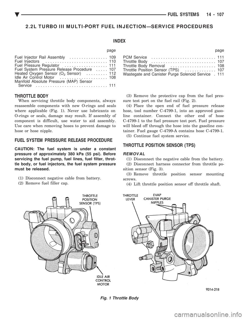
When servicing throttle body components, always
reassemble components with new O-rings and seals
where applicable (Fig. 1). Never use lubricants on
O-rings or seals, damage may result. If assembly of
component is difficult, use water to aid assembly.
Use care when removing hoses to prevent damage to
hose or hose nipple.
FUEL SYSTEM PRESSURE RELEASE PROCEDURE
CAUTION: The fuel system is under a constant
pressure of approximately 380 kPa (55 psi). Before
servicing the fuel pump, fuel lines, fuel filter, throt-
tle body, or fuel injectors, the fuel system pressure
must be released.
(1) Disconnect negative cable from battery.
(2) Remove fuel filler cap. (3) Remove the protective cap from the fuel pres-
sure test port on the fuel rail (Fig. 2). (4) Place the open end of fuel pressure release
hose, tool number C-4799-1, into an approved gaso-
line container. Connect the other end of hose
C-4799-1 to the fuel pressure test port. Fuel pressure
will bleed off through the hose into the gasoline con-
tainer. Fuel gauge C-4799-A contains hose C-4799-1. (5) Continue fuel system service.THROTTLE POSITION SENSOR (TPS)
REMOVAL
(1) Disconnect the negative cable from the battery.
(2) Disconnect harness connector from throttle po-
sition sensor (Fig. 3). (3) Remove throttle position sensor mounting
screws. (4) Lift throttle position sensor off throttle shaft.
Fig. 1 Throttle Body
Ä FUEL SYSTEMS 14 - 107