buttons CHEVROLET DYNASTY 1993 User Guide
[x] Cancel search | Manufacturer: CHEVROLET, Model Year: 1993, Model line: DYNASTY, Model: CHEVROLET DYNASTY 1993Pages: 2438, PDF Size: 74.98 MB
Page 433 of 2438
(4) Drive the vehicle 1 to 3 complete circles. The
CAL light will then go off, showing the compass is
calibrated. If the compass portion of the display:
² It does not display.
² Readings are not accurate after calibration.
² The vehicle may have too much magnetism for the
compass to be accurate.
² The compass circuitry is not working properly.
² Refer to Variance Procedure, Demagnetizing Pro-
cedure and/or Compass Diagnostics.
VARIANCE PROCEDURE
Variance is the difference between magnetic North
and geographic North. In some areas the difference
between magnetic and geographic North is great
enough to cause the compass to give false readings. If
this occurs, the variance must be set. To set the variance, depress and hold down both
the Comp/Temp button and the U.S./Metric button.
The display will go off and after 5 seconds the VAR
light will come on. Release both buttons. Using the
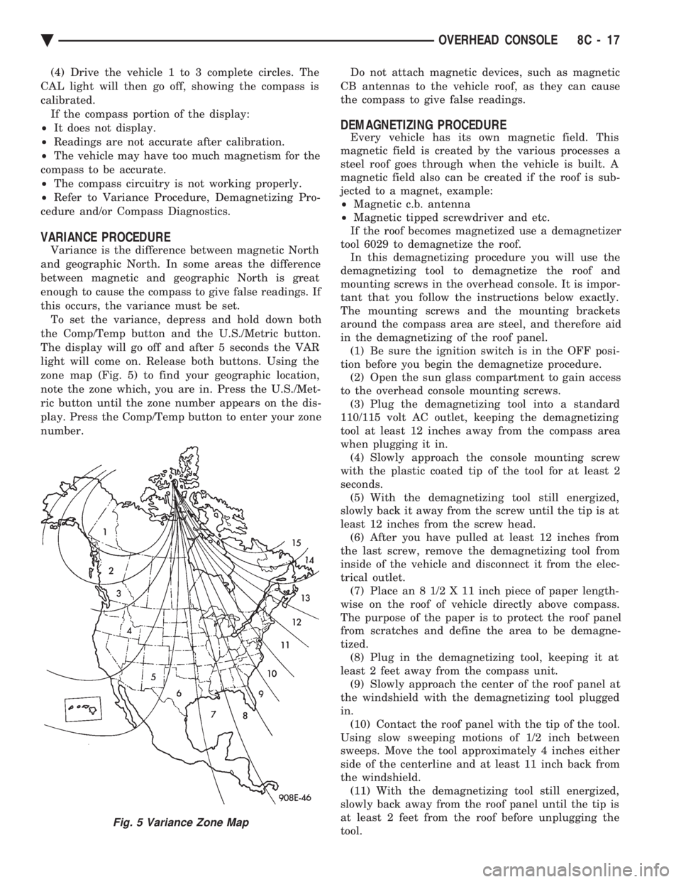
zone map (Fig. 5) to find your geographic location,
note the zone which, you are in. Press the U.S./Met-
ric button until the zone number appears on the dis-
play. Press the Comp/Temp button to enter your zone
number. Do not attach magnetic devices, such as magnetic
CB antennas to the vehicle roof, as they can cause
the compass to give false readings.
DEMAGNETIZING PROCEDURE
Every vehicle has its own magnetic field. This
magnetic field is created by the various processes a
steel roof goes through when the vehicle is built. A
magnetic field also can be created if the roof is sub-
jected to a magnet, example:
² Magnetic c.b. antenna
² Magnetic tipped screwdriver and etc.
If the roof becomes magnetized use a demagnetizer
tool 6029 to demagnetize the roof. In this demagnetizing procedure you will use the
demagnetizing tool to demagnetize the roof and
mounting screws in the overhead console. It is impor-
tant that you follow the instructions below exactly.
The mounting screws and the mounting brackets
around the compass area are steel, and therefore aid
in the demagnetizing of the roof panel. (1) Be sure the ignition switch is in the OFF posi-
tion before you begin the demagnetize procedure. (2) Open the sun glass compartment to gain access
to the overhead console mounting screws. (3) Plug the demagnetizing tool into a standard
110/115 volt AC outlet, keeping the demagnetizing
tool at least 12 inches away from the compass area
when plugging it in. (4) Slowly approach the console mounting screw
with the plastic coated tip of the tool for at least 2
seconds. (5) With the demagnetizing tool still energized,
slowly back it away from the screw until the tip is at
least 12 inches from the screw head. (6) After you have pulled at least 12 inches from
the last screw, remove the demagnetizing tool from
inside of the vehicle and disconnect it from the elec-
trical outlet. (7) Place an 8 1/2 X 11 inch piece of paper length-
wise on the roof of vehicle directly above compass.
The purpose of the paper is to protect the roof panel
from scratches and define the area to be demagne-
tized. (8) Plug in the demagnetizing tool, keeping it at
least 2 feet away from the compass unit. (9) Slowly approach the center of the roof panel at
the windshield with the demagnetizing tool plugged
in. (10) Contact the roof panel with the tip of the tool.
Using slow sweeping motions of 1/2 inch between
sweeps. Move the tool approximately 4 inches either
side of the centerline and at least 11 inch back from
the windshield. (11) With the demagnetizing tool still energized,
slowly back away from the roof panel until the tip is
at least 2 feet from the roof before unplugging the
tool.
Fig. 5 Variance Zone Map
Ä OVERHEAD CONSOLE 8C - 17
Page 437 of 2438
AP BODY INDEX
page page
Ambient Temperature Sensor Removal ........ 25
Compass Calibration ...................... 21
Compass Diagnostics ..................... 23
Compass Module Replacement .............. 25
Demagnetizing Procedure .................. 22 Map Reading Lamps Operation
.............. 21
Overhead Console Replacement ............. 25
Thermometer and Compass ................ 21
Variance Procedure ....................... 22
MAP READING LAMPS OPERATION
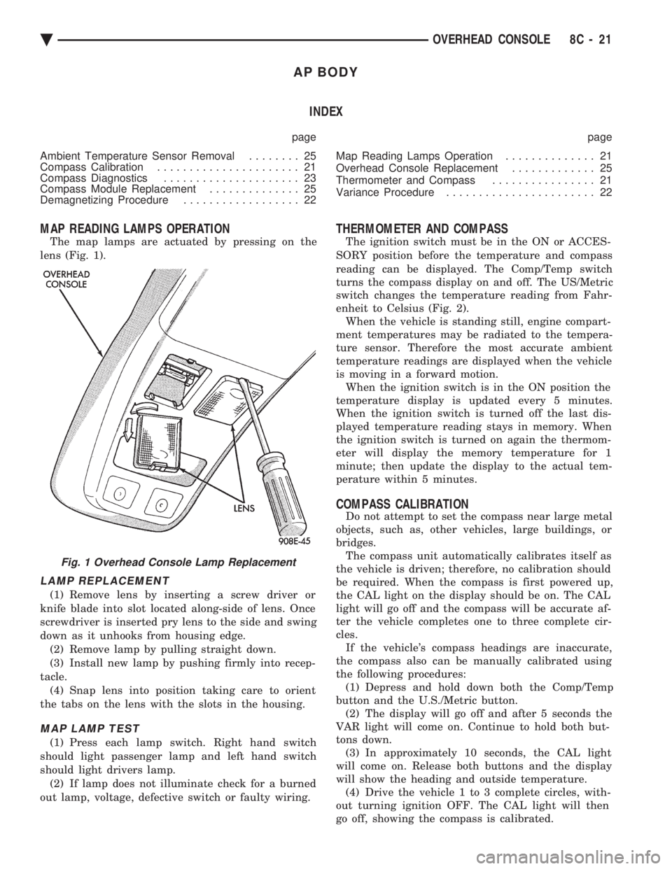
The map lamps are actuated by pressing on the
lens (Fig. 1).
LAMP REPLACEMENT
(1) Remove lens by inserting a screw driver or
knife blade into slot located along-side of lens. Once
screwdriver is inserted pry lens to the side and swing
down as it unhooks from housing edge. (2) Remove lamp by pulling straight down.
(3) Install new lamp by pushing firmly into recep-
tacle. (4) Snap lens into position taking care to orient
the tabs on the lens with the slots in the housing.
MAP LAMP TEST
(1) Press each lamp switch. Right hand switch
should light passenger lamp and left hand switch
should light drivers lamp. (2) If lamp does not illuminate check for a burned
out lamp, voltage, defective switch or faulty wiring.
THERMOMETER AND COMPASS
The ignition switch must be in the ON or ACCES-
SORY position before the temperature and compass
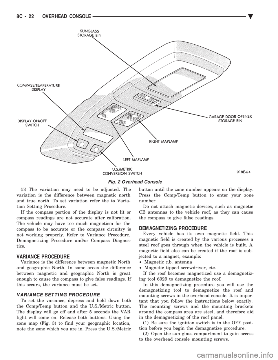
reading can be displayed. The Comp/Temp switch
turns the compass display on and off. The US/Metric
switch changes the temperature reading from Fahr-
enheit to Celsius (Fig. 2). When the vehicle is standing still, engine compart-
ment temperatures may be radiated to the tempera-
ture sensor. Therefore the most accurate ambient
temperature readings are displayed when the vehicle
is moving in a forward motion. When the ignition switch is in the ON position the
temperature display is updated every 5 minutes.
When the ignition switch is turned off the last dis-
played temperature reading stays in memory. When
the ignition switch is turned on again the thermom-
eter will display the memory temperature for 1
minute; then update the display to the actual tem-
perature within 5 minutes.
COMPASS CALIBRATION
Do not attempt to set the compass near large metal
objects, such as, other vehicles, large buildings, or
bridges. The compass unit automatically calibrates itself as
the vehicle is driven; therefore, no calibration should
be required. When the compass is first powered up,
the CAL light on the display should be on. The CAL
light will go off and the compass will be accurate af-
ter the vehicle completes one to three complete cir-
cles. If the vehicle's compass headings are inaccurate,
the compass also can be manually calibrated using
the following procedures: (1) Depress and hold down both the Comp/Temp
button and the U.S./Metric button. (2) The display will go off and after 5 seconds the
VAR light will come on. Continue to hold both but-
tons down. (3) In approximately 10 seconds, the CAL light
will come on. Release both buttons and the display
will show the heading and outside temperature. (4) Drive the vehicle 1 to 3 complete circles, with-
out turning ignition OFF. The CAL light will then
go off, showing the compass is calibrated.
Fig. 1 Overhead Console Lamp Replacement
Ä OVERHEAD CONSOLE 8C - 21
Page 438 of 2438
(5) The variation may need to be adjusted. The
variation is the difference between magnetic north
and true north. To set variation refer the to Varia-
tion Setting Procedure. If the compass portion of the display is not lit or
compass readings are not accurate after calibration.
The vehicle may have too much magnetism for the
compass to be accurate or the compass circuitry is
not working properly. Refer to Variance Procedure,
Demagnetizing Procedure and/or Compass Diagnos-
tics.
VARIANCE PROCEDURE
Variance is the difference between magnetic North
and geographic North. In some areas the difference
between magnetic and geographic North is great
enough to cause the compass to give false readings. If
this occurs, the variance must be set.
VARIANCE SETTING PROCEDURE
To set the variance, depress and hold down both
the Comp/Temp button and the U.S./Metric button.
The display will go off and after 5 seconds the VAR
light will come on. Release both buttons. Using the
zone map (Fig. 3) to find your geographic location,
note the zone which you are in. Press the U.S./Metric button until the zone number appears on the display.
Press the Comp/Temp button to enter your zone
number. Do not attach magnetic devices, such as magnetic
CB antennas to the vehicle roof, as they can cause
the compass to give false readings.
DEMAGNETIZING PROCEDURE
Every vehicle has its own magnetic field. This
magnetic field is created by the various processes a
steel roof goes through when the vehicle is built. A
magnetic field also can be created if the roof is sub-
jected to a magnet, example:
² Magnetic c.b. antenna
² Magnetic tipped screwdriver, etc.
If the roof becomes magnetized use a demagnetiz-
ing tool 6029 to demagnetize the roof. In this demagnetizing procedure you will use the
demagnetizing tool to demagnetize the roof and
mounting screws in the overhead console. It is impor-
tant that you follow the instructions below exactly.
The mounting screws and the mounting brackets
around the compass area are steel, and therefore aid
in the demagnetizing of the roof panel. (1) Be sure the ignition switch is in the OFF posi-
tion before you begin the demagnetize procedure. (2) Open the sun glass compartment to gain access
to the overhead console mounting screws.
Fig. 2 Overhead Console
8C - 22 OVERHEAD CONSOLE Ä
Page 513 of 2438
(3) Remove four screws from ash receiver/cup
holder housing. (4) For installation reverse above procedures.
AIR CONDITIONING CONTROLREPLACEMENT
(1) Disconnect battery negative cable and isolate
or remove fuse #2 prior to removing switch or wires
may short to ground. (2) Remove center bezel. Disconnect ash receiver
lamp socket. (3) Remove glove box assembly. Refer to Glove Box
Assembly Replacement. (4) Reach through glove box opening and discon-
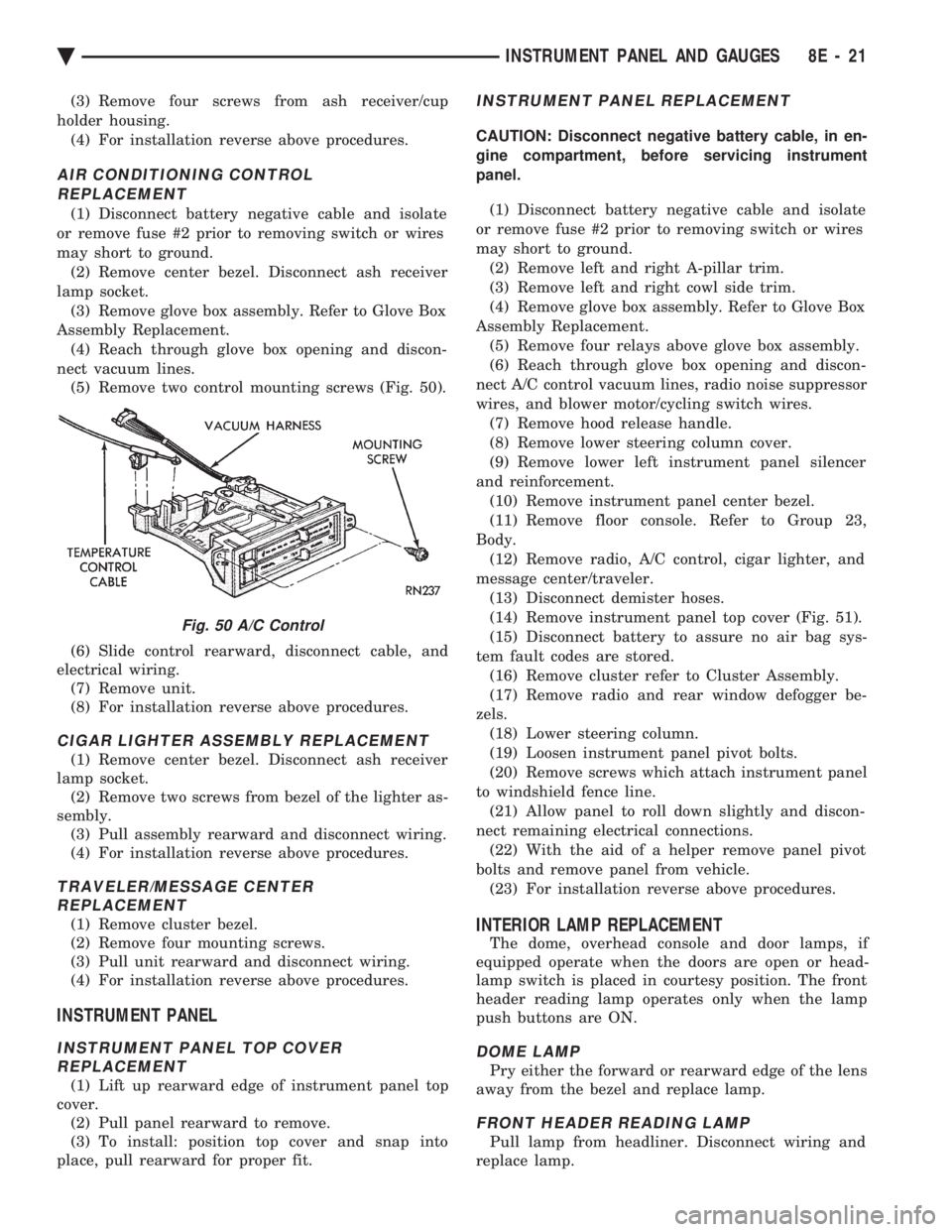
nect vacuum lines. (5) Remove two control mounting screws (Fig. 50).
(6) Slide control rearward, disconnect cable, and
electrical wiring. (7) Remove unit.
(8) For installation reverse above procedures.
CIGAR LIGHTER ASSEMBLY REPLACEMENT
(1) Remove center bezel. Disconnect ash receiver
lamp socket. (2) Remove two screws from bezel of the lighter as-
sembly. (3) Pull assembly rearward and disconnect wiring.
(4) For installation reverse above procedures.
TRAVELER/MESSAGE CENTER REPLACEMENT
(1) Remove cluster bezel.
(2) Remove four mounting screws.
(3) Pull unit rearward and disconnect wiring.
(4) For installation reverse above procedures.
INSTRUMENT PANEL
INSTRUMENT PANEL TOP COVER REPLACEMENT
(1) Lift up rearward edge of instrument panel top
cover. (2) Pull panel rearward to remove.
(3) To install: position top cover and snap into
place, pull rearward for proper fit.
INSTRUMENT PANEL REPLACEMENT
CAUTION: Disconnect negative battery cable, in en-
gine compartment, before servicing instrument
panel.
(1) Disconnect battery negative cable and isolate
or remove fuse #2 prior to removing switch or wires
may short to ground. (2) Remove left and right A-pillar trim.
(3) Remove left and right cowl side trim.
(4) Remove glove box assembly. Refer to Glove Box
Assembly Replacement. (5) Remove four relays above glove box assembly.
(6) Reach through glove box opening and discon-
nect A/C control vacuum lines, radio noise suppressor
wires, and blower motor/cycling switch wires. (7) Remove hood release handle.
(8) Remove lower steering column cover.
(9) Remove lower left instrument panel silencer
and reinforcement. (10) Remove instrument panel center bezel.
(11) Remove floor console. Refer to Group 23,
Body. (12) Remove radio, A/C control, cigar lighter, and
message center/traveler. (13) Disconnect demister hoses.
(14) Remove instrument panel top cover (Fig. 51).
(15) Disconnect battery to assure no air bag sys-
tem fault codes are stored. (16) Remove cluster refer to Cluster Assembly.
(17) Remove radio and rear window defogger be-
zels. (18) Lower steering column.
(19) Loosen instrument panel pivot bolts.
(20) Remove screws which attach instrument panel
to windshield fence line. (21) Allow panel to roll down slightly and discon-
nect remaining electrical connections. (22) With the aid of a helper remove panel pivot
bolts and remove panel from vehicle. (23) For installation reverse above procedures.
INTERIOR LAMP REPLACEMENT
The dome, overhead console and door lamps, if
equipped operate when the doors are open or head-
lamp switch is placed in courtesy position. The front
header reading lamp operates only when the lamp
push buttons are ON.
DOME LAMP
Pry either the forward or rearward edge of the lens
away from the bezel and replace lamp.
FRONT HEADER READING LAMP
Pull lamp from headliner. Disconnect wiring and
replace lamp.
Fig. 50 A/C Control
Ä INSTRUMENT PANEL AND GAUGES 8E - 21
Page 529 of 2438
CONDITION: US/METRIC MODES WILL NOT TOGGLE OR TRIP ODOMETER WILL NOTRESET
PROCEDURE
(1) Perform cluster self-diagnostics to determine if
push buttons are operational. (2) Refer to the Body Chassis Diagnostic Manual
to diagnose CCD Bus. The US/Metric toggle and trip
odometer reset are activated over the CCD Bus.
ODOMETER ADJUSTMENT
The odometer memory is no longer retained in the
cluster. This information is stored in the body con-
troller. Therefore, there is no adjustment procedure.
If the cluster is replaced odometer value will not
change. If the body controller is replaced the mileage
may be transferred using the DRB II. Refer to the
Body Chassis Diagnostic Manual for the procedure.
SWITCH AND PANEL COMPONENT SERVICE
MESSAGE CENTER REPLACEMENT
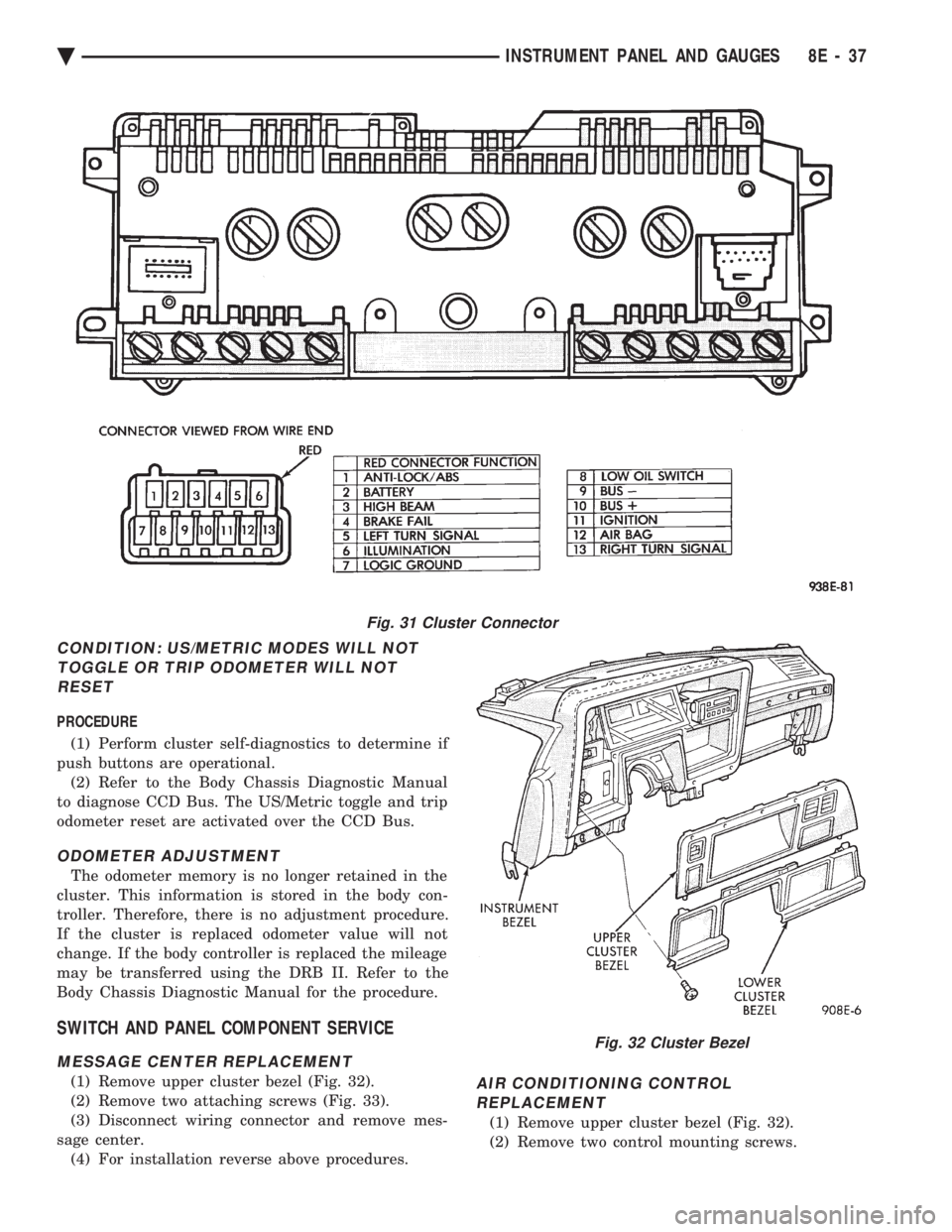
(1) Remove upper cluster bezel (Fig. 32).
(2) Remove two attaching screws (Fig. 33).
(3) Disconnect wiring connector and remove mes-
sage center. (4) For installation reverse above procedures.AIR CONDITIONING CONTROLREPLACEMENT
(1) Remove upper cluster bezel (Fig. 32).
(2) Remove two control mounting screws.
Fig. 31 Cluster Connector
Fig. 32 Cluster Bezel
Ä INSTRUMENT PANEL AND GAUGES 8E - 37
Page 543 of 2438
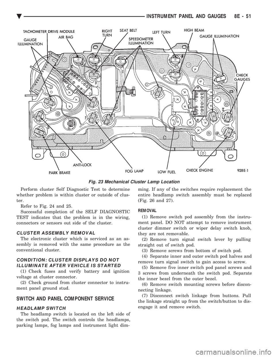
Perform cluster Self Diagnostic Test to determine
whether problem is within cluster or outside of clus-
ter. Refer to Fig. 24 and 25.
Successful completion of the SELF DIAGNOSTIC
TEST indicates that the problem is in the wiring,
connectors or sensors out side of the cluster.
CLUSTER ASSEMBLY REMOVAL
The electronic cluster which is serviced as an as-
sembly is removed with the same procedure as the
conventional cluster.
CONDITION: CLUSTER DISPLAYS DO NOT ILLUMINATE AFTER VEHICLE IS STARTED
(1) Check fuses and verify battery and ignition
voltage at cluster connector. (2) Check ground from cluster connector to instru-
ment panel ground stud.
SWITCH AND PANEL COMPONENT SERVICE
HEADLAMP SWITCH
The headlamp switch is located on the left side of
the switch pod. The switch controls the headlamps,
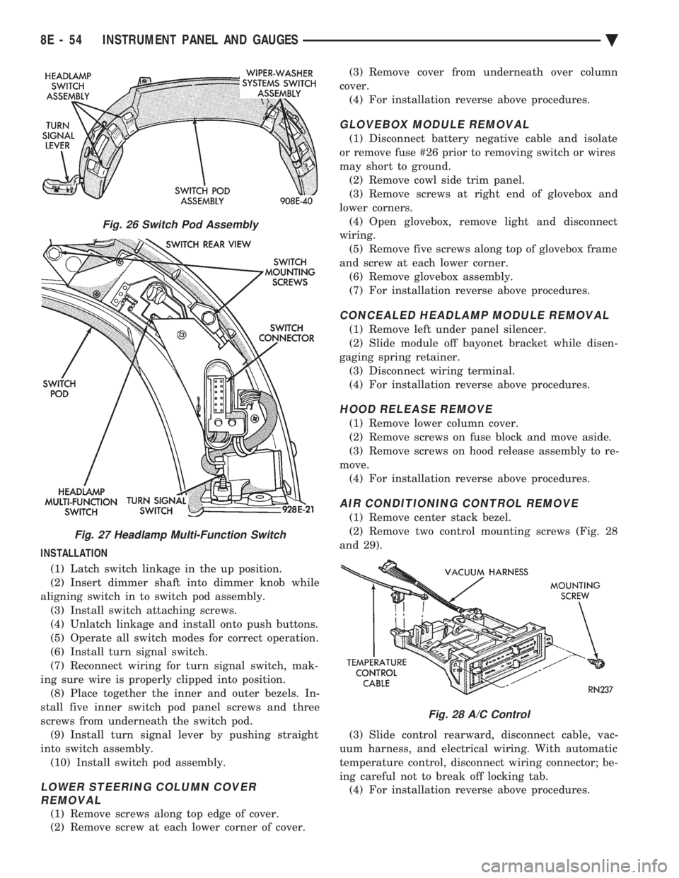
parking lamps, fog lamps and instrument light dim- ming. If any of the switches require replacement the
entire headlamp switch assembly must be replaced
(Fig. 26 and 27).
REMOVAL
(1) Remove switch pod assembly from the instru-
ment panel. DO NOT attempt to remove instrument
cluster dimmer switch or wiper delay switch knob,
they are not removable. (2) Remove turn signal switch lever by pulling
straight out of switch pod. (3) Remove screws from bottom of switch pod.
(4) Separate inner and outer switch pod halves and
remove turn signal switch to gain access to screw. (5) Remove five inner switch pod panel screws and
3 screws from underneath the switch pod. Separate
the inner bezel from the outer bezel. (6) Remove switch mounting screws before discon-
necting linkage. (7) Disconnect switch linkage from buttons. Pull
the linkage straight up from the switch/button to dis-
engage it and remove switch.
Fig. 23 Mechanical Cluster Lamp Location
Ä INSTRUMENT PANEL AND GAUGES 8E - 51
Page 546 of 2438
INSTALLATION (1) Latch switch linkage in the up position.
(2) Insert dimmer shaft into dimmer knob while
aligning switch in to switch pod assembly. (3) Install switch attaching screws.
(4) Unlatch linkage and install onto push buttons.
(5) Operate all switch modes for correct operation.
(6) Install turn signal switch.
(7) Reconnect wiring for turn signal switch, mak-
ing sure wire is properly clipped into position. (8) Place together the inner and outer bezels. In-
stall five inner switch pod panel screws and three
screws from underneath the switch pod. (9) Install turn signal lever by pushing straight
into switch assembly. (10) Install switch pod assembly.
LOWER STEERING COLUMN COVER REMOVAL
(1) Remove screws along top edge of cover.
(2) Remove screw at each lower corner of cover. (3) Remove cover from underneath over column
cover. (4) For installation reverse above procedures.
GLOVEBOX MODULE REMOVAL
(1) Disconnect battery negative cable and isolate
or remove fuse #26 prior to removing switch or wires
may short to ground. (2) Remove cowl side trim panel.
(3) Remove screws at right end of glovebox and
lower corners. (4) Open glovebox, remove light and disconnect
wiring. (5) Remove five screws along top of glovebox frame
and screw at each lower corner. (6) Remove glovebox assembly.
(7) For installation reverse above procedures.
CONCEALED HEADLAMP MODULE REMOVAL
(1) Remove left under panel silencer.
(2) Slide module off bayonet bracket while disen-
gaging spring retainer. (3) Disconnect wiring terminal.
(4) For installation reverse above procedures.
HOOD RELEASE REMOVE
(1) Remove lower column cover.
(2) Remove screws on fuse block and move aside.
(3) Remove screws on hood release assembly to re-
move. (4) For installation reverse above procedures.
AIR CONDITIONING CONTROL REMOVE
(1) Remove center stack bezel.
(2) Remove two control mounting screws (Fig. 28
and 29).
(3) Slide control rearward, disconnect cable, vac-
uum harness, and electrical wiring. With automatic
temperature control, disconnect wiring connector; be-
ing careful not to break off locking tab. (4) For installation reverse above procedures.
Fig. 26 Switch Pod Assembly
Fig. 27 Headlamp Multi-Function Switch
Fig. 28 A/C Control
8E - 54 INSTRUMENT PANEL AND GAUGES Ä
Page 599 of 2438
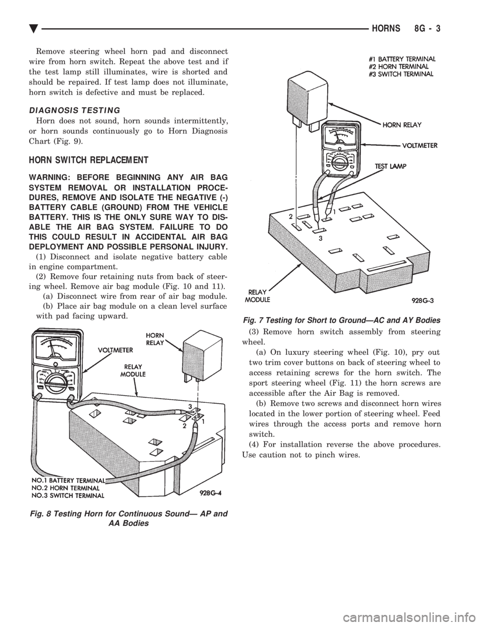
Remove steering wheel horn pad and disconnect
wire from horn switch. Repeat the above test and if
the test lamp still illuminates, wire is shorted and
should be repaired. If test lamp does not illuminate,
horn switch is defective and must be replaced.
DIAGNOSIS TESTING
Horn does not sound, horn sounds intermittently,
or horn sounds continuously go to Horn Diagnosis
Chart (Fig. 9).
HORN SWITCH REPLACEMENT
WARNING: BEFORE BEGINNING ANY AIR BAG
SYSTEM REMOVAL OR INSTALLATION PROCE-
DURES, REMOVE AND ISOLATE THE NEGATIVE (-)
BATTERY CABLE (GROUND) FROM THE VEHICLE
BATTERY. THIS IS THE ONLY SURE WAY TO DIS-
ABLE THE AIR BAG SYSTEM. FAILURE TO DO
THIS COULD RESULT IN ACCIDENTAL AIR BAG
DEPLOYMENT AND POSSIBLE PERSONAL INJURY. (1) Disconnect and isolate negative battery cable
in engine compartment. (2) Remove four retaining nuts from back of steer-
ing wheel. Remove air bag module (Fig. 10 and 11). (a) Disconnect wire from rear of air bag module.
(b) Place air bag module on a clean level surface
with pad facing upward.
(3) Remove horn switch assembly from steering
wheel. (a) On luxury steering wheel (Fig. 10), pry out
two trim cover buttons on back of steering wheel to
access retaining screws for the horn switch. The
sport steering wheel (Fig. 11) the horn screws are
accessible after the Air Bag is removed. (b) Remove two screws and disconnect horn wires
located in the lower portion of steering wheel. Feed
wires through the access ports and remove horn
switch.
(4) For installation reverse the above procedures.
Use caution not to pinch wires.
Fig. 8 Testing Horn for Continuous SoundÐ AP and AA Bodies
Fig. 7 Testing for Short to GroundÐAC and AY Bodies
Ä HORNS 8G - 3
Page 603 of 2438
VEHICLE SPEED CONTROL
CONTENTS
page page
CHECKING FOR FAULT CODE .............. 3
DIAGNOSIS PROCEDURES ................ 2
GENERAL INFORMATION .................. 1
INOPERATIVE SYSTEM ................... 3
POWERTRAIN CONTROL MODULE ELECTRICAL TEST ................................ 5
ROAD TEST ............................ 2
SERVO ELECTRICAL TESTS ............... 4
SERVO UNIT ............................ 9 SERVO VACUUM TEST
................... 9
STOP LAMP VEHICLE SPEED CONTROL SWITCH TEST ......................... 8
VACUUM SUPPLY TEST .................. 9
VEHICLE SPEED CONTROL SWITCH REMOVAL ........................... 10
VEHICLE SPEED CONTROL SWITCH TEST . . . 8
VEHICLE SPEED CONTROL ELECTRICAL TESTS ............................... 3
GENERAL INFORMATION
The vehicle speed control is electronically con-
trolled and vacuum operated. The electronic control
is integrated into the powertrain control module, lo-
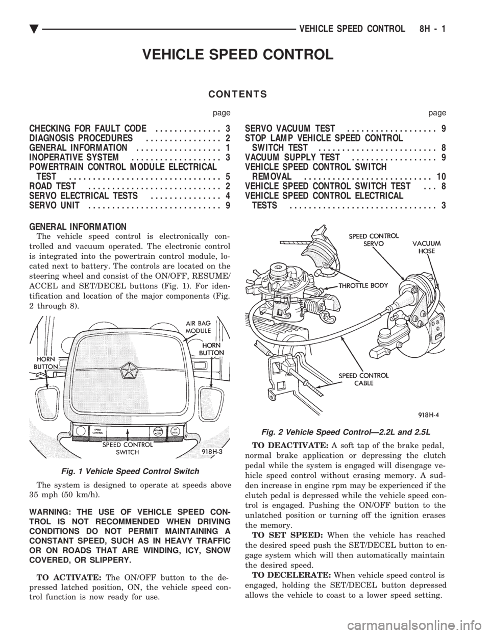
cated next to battery. The controls are located on the
steering wheel and consist of the ON/OFF, RESUME/
ACCEL and SET/DECEL buttons (Fig. 1). For iden-
tification and location of the major components (Fig.
2 through 8).
The system is designed to operate at speeds above
35 mph (50 km/h).
WARNING: THE USE OF VEHICLE SPEED CON-
TROL IS NOT RECOMMENDED WHEN DRIVING
CONDITIONS DO NOT PERMIT MAINTAINING A
CONSTANT SPEED, SUCH AS IN HEAVY TRAFFIC
OR ON ROADS THAT ARE WINDING, ICY, SNOW
COVERED, OR SLIPPERY.
TO ACTIVATE: The ON/OFF button to the de-
pressed latched position, ON, the vehicle speed con-
trol function is now ready for use. TO DEACTIVATE:
A soft tap of the brake pedal,
normal brake application or depressing the clutch
pedal while the system is engaged will disengage ve-
hicle speed control without erasing memory. A sud-
den increase in engine rpm may be experienced if the
clutch pedal is depressed while the vehicle speed con-
trol is engaged. Pushing the ON/OFF button to the
unlatched position or turning off the ignition erases
the memory. TO SET SPEED: When the vehicle has reached
the desired speed push the SET/DECEL button to en-
gage system which will then automatically maintain
the desired speed. TO DECELERATE: When vehicle speed control is
engaged, holding the SET/DECEL button depressed
allows the vehicle to coast to a lower speed setting.
Fig. 1 Vehicle Speed Control Switch
Fig. 2 Vehicle Speed ControlÐ2.2L and 2.5L
Ä VEHICLE SPEED CONTROL 8H - 1
Page 635 of 2438
WIPER SWITCH SERVICE PROCEDURE
WARNING: ON VEHICLES EQUIPPED WITH AIR-
BAG, SEE GROUP 8M, RESTRAINT SYSTEMS FOR
STEERING WHEEL OR COLUMN REMOVAL PROCE-
DURES.
AC AND AY BODIES
The wiper switch is part of the multi-function
switch assembly. If the wiper switch fails, the multi-
function switch must be replaced. Refer to Group 8J,
Turn Signals and Hazard Warning Flasher for multi-
function switch service procedure.
AG AND AJ BODIES
REMOVAL
(1) Remove switch pod assembly from instrument
panel. (2) Remove five inner switch pod panel.
(3) Unhook switch linkage from buttons.
(4) Remove switch mounting screws.
(5) Remove switch.
INSTALLATION (1) Latch switch linkage in the up position.
(2) Insert switch into switch pod and install
mounting screws. (3) Unlatch linkage and install onto push buttons.
(4) Operate all switch modes for correct operation.
(5) Reinstall five inner switch pod panel screws.
(6) Reinstall switch pod assembly.
PULSE INTERMITTENT WINDSHIELD WIPER
CONTROLLER (PIWWC)
The controller is a part of the washing and wiper
system which includes:
² Pulse intermittent windshield wiper controller
² Wiper blades and arms
² Wiper motor
² Windshield washer reservoir
² Wiring harness
² Windshield washer pump
² Windshield washer hoses
Any part not working properly could cause, the
whole system not to work properly or at all. If the
system is not working proper, check all parts before
taking any action of part replacements.
The controller controls the pulse/wipe and the inter-
mittent modes only. The time delay in the intermittent
wipe mode is a minimum of 45 to a maximum of 25 sec-
onds depending on the switch setting.
The wash function can be turn ON with the wiper
control switch in the OFF position. Pressing the
wash button on the end of the level will operate the
washer pump until released. The wipers will operate
while the pump is operating and continue for about
three addition wipes ( 61) after before parking.
AA BODY
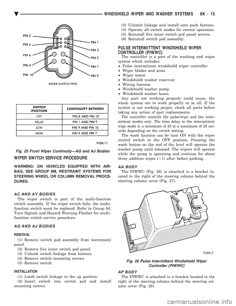
The PIWWC (Fig. 26) is attached to a bracket lo-
cated to the right of the steering column behind the
steering column cover (Fig. 27).
AP BODY
The PIWWC is attached to a bracket located to the
right of the steering column behind the steering col-
umn cover (Fig. 28).
Fig. 25 Front Wiper ContinuityÐAG and AJ Bodies
Fig. 26 Pulse Intermittent Windshield Wiper Controller (PIWWC)
Ä WINDSHIELD WIPER AND WASHER SYSTEMS 8K - 15