check engine light CHEVROLET DYNASTY 1993 User Guide
[x] Cancel search | Manufacturer: CHEVROLET, Model Year: 1993, Model line: DYNASTY, Model: CHEVROLET DYNASTY 1993Pages: 2438, PDF Size: 74.98 MB
Page 437 of 2438
AP BODY INDEX
page page
Ambient Temperature Sensor Removal ........ 25
Compass Calibration ...................... 21
Compass Diagnostics ..................... 23
Compass Module Replacement .............. 25
Demagnetizing Procedure .................. 22 Map Reading Lamps Operation
.............. 21
Overhead Console Replacement ............. 25
Thermometer and Compass ................ 21
Variance Procedure ....................... 22
MAP READING LAMPS OPERATION
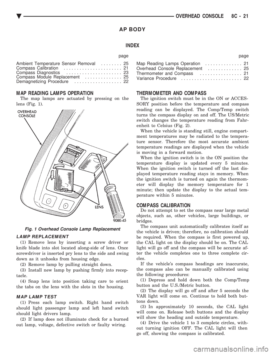
The map lamps are actuated by pressing on the
lens (Fig. 1).
LAMP REPLACEMENT
(1) Remove lens by inserting a screw driver or
knife blade into slot located along-side of lens. Once
screwdriver is inserted pry lens to the side and swing
down as it unhooks from housing edge. (2) Remove lamp by pulling straight down.
(3) Install new lamp by pushing firmly into recep-
tacle. (4) Snap lens into position taking care to orient
the tabs on the lens with the slots in the housing.
MAP LAMP TEST
(1) Press each lamp switch. Right hand switch
should light passenger lamp and left hand switch
should light drivers lamp. (2) If lamp does not illuminate check for a burned
out lamp, voltage, defective switch or faulty wiring.
THERMOMETER AND COMPASS
The ignition switch must be in the ON or ACCES-
SORY position before the temperature and compass
reading can be displayed. The Comp/Temp switch
turns the compass display on and off. The US/Metric
switch changes the temperature reading from Fahr-
enheit to Celsius (Fig. 2). When the vehicle is standing still, engine compart-
ment temperatures may be radiated to the tempera-
ture sensor. Therefore the most accurate ambient
temperature readings are displayed when the vehicle
is moving in a forward motion. When the ignition switch is in the ON position the
temperature display is updated every 5 minutes.
When the ignition switch is turned off the last dis-
played temperature reading stays in memory. When
the ignition switch is turned on again the thermom-
eter will display the memory temperature for 1
minute; then update the display to the actual tem-
perature within 5 minutes.
COMPASS CALIBRATION
Do not attempt to set the compass near large metal
objects, such as, other vehicles, large buildings, or
bridges. The compass unit automatically calibrates itself as
the vehicle is driven; therefore, no calibration should
be required. When the compass is first powered up,
the CAL light on the display should be on. The CAL
light will go off and the compass will be accurate af-
ter the vehicle completes one to three complete cir-
cles. If the vehicle's compass headings are inaccurate,
the compass also can be manually calibrated using
the following procedures: (1) Depress and hold down both the Comp/Temp
button and the U.S./Metric button. (2) The display will go off and after 5 seconds the
VAR light will come on. Continue to hold both but-
tons down. (3) In approximately 10 seconds, the CAL light
will come on. Release both buttons and the display
will show the heading and outside temperature. (4) Drive the vehicle 1 to 3 complete circles, with-
out turning ignition OFF. The CAL light will then
go off, showing the compass is calibrated.
Fig. 1 Overhead Console Lamp Replacement
Ä OVERHEAD CONSOLE 8C - 21
Page 444 of 2438
Light scaling of the terminals can be cleaned with
a sharp knife. If the terminals are heavily scaled, re-
place the distributor cap. A cap that is greasy, dirty or has a powder-like
substance on the inside should be cleaned with a so-
lution of warm water and a mild detergent. Scrub
the cap with a soft brush. Thoroughly rinse the cap
and dry it with a clean soft cloth.
ROTOR
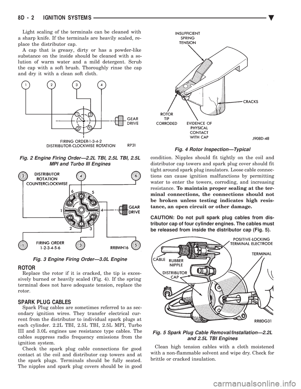
Replace the rotor if it is cracked, the tip is exces-
sively burned or heavily scaled (Fig. 4). If the spring
terminal does not have adequate tension, replace the
rotor.
SPARK PLUG CABLES
Spark Plug cables are sometimes referred to as sec-
ondary ignition wires. They transfer electrical cur-
rent from the distributor to individual spark plugs at
each cylinder. 2.2L TBI, 2.5L TBI, 2.5L MPI, Turbo
III and 3.0L engines use resistance type cables. The
cables suppress radio frequency emissions from the
ignition system. Check the spark plug cable connections for good
contact at the coil and distributor cap towers and at
the spark plugs. Terminals should be fully seated.
The nipples and spark plug covers should be in good condition. Nipples should fit tightly on the coil and
distributor cap towers and spark plug cover should fit
tight around spark plug insulators. Loose cable connec-
tions can cause ignition malfunctions by permitting
water to enter the towers, corroding, and increasing
resistance. To maintain proper sealing at the ter-
minal connections, the connections should not
be broken unless testing indicates high resis-
tance, an open circuit or other damage.
CAUTION: Do not pull spark plug cables from dis-
tributor cap of four cylinder engines. The cables must
be released from inside the distributor cap (Fig. 5).
Clean high tension cables with a cloth moistened
with a non-flammable solvent and wipe dry. Check for
brittle or cracked insulation.
Fig. 2 Engine Firing OrderÐ2.2L TBI, 2.5L TBI, 2.5L MPI and Turbo III Engines
Fig. 3 Engine Firing OrderÐ3.0L Engine
Fig. 4 Rotor InspectionÐTypical
Fig. 5 Spark Plug Cable Removal/InstallationÐ2.2L and 2.5L TBI Engines
8D - 2 IGNITION SYSTEMS Ä
Page 445 of 2438
When testing secondary cables for punctures and
cracks with an oscilloscope follow the equipment
manufacturers instructions. If an oscilloscope is not available, secondary cables
can be tested as follows:
CAUTION: Do not leave any one spark plug cable
disconnected any longer than necessary during test-
ing. Excessive heat could damage the catalytic con-
verter. Total test time must not exceed ten minutes.
(a) With the engine not running, connect one end
of a test probe to a good ground. Use a probe made of
insulated wire with insulated alligator clips on each
end. (b) With engine running, move test probe along
entire length of all cables (approximately 0 to 1/8
inch gap). If punctures or cracks are present there
will be a noticeable spark jump from the faulty area
to the probe. Check the coil cable the same way.
Replace cracked, leaking or faulty cables.
When replacing cables, install the new high
tension cable and nipple assembly over cap or
coil tower. When entering the terminal into the
tower, push lightly, then pinch the large diam-
eter of nipple to release air trapped between the
nipple and tower. Continue pushing on the cable
and nipple until cables are properly seated in the
cap towers. A snap should be heard as terminal
goes into place. Use the same procedure to install cable in coil tower.
Wipe the spark plug insulator clean before reinstalling
cable and cover. Use the following procedure when removing the high
tension cable from the spark plug. First, remove the
cable from the retaining bracket. Then grasp the ter-
minal as close as possible to the spark plug. Rotate the
cover and pull the cable straight back. Pulling on the
cable itself will damage the conductor and termi-
nal connection. Do not use pliers and do not pull
the cable at an angle. Doing so will damage the
insulation, cable terminal or the spark plug in-
sulator. Wipe spark plug insulator clean before
reinstalling cable and cover. Resistance type cable is identified by the words
Electronic Suppression printed on the cable jacket.
Use an ohmmeter to check resistance type cable for
open circuits, loose terminals or high resistance as
follows: (a) Remove cable from spark plug.
(b) Lift distributor cap from distributor with
cables intact. Do not remove cables from cap. The
cables must be removed from the spark plugs. (c) Connect the ohmmeter between spark plug end
terminal and the corresponding electrode inside the
cap, make sure ohmmeter probes are in good contact.
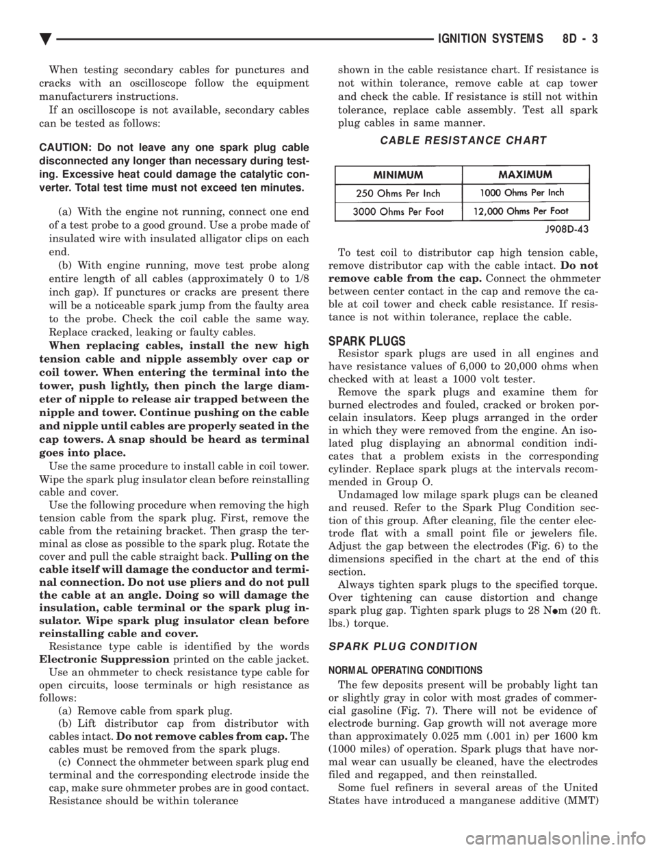
Resistance should be within tolerance shown in the cable resistance chart. If resistance is
not within tolerance, remove cable at cap tower
and check the cable. If resistance is still not within
tolerance, replace cable assembly. Test all spark
plug cables in same manner.
To test coil to distributor cap high tension cable,
remove distributor cap with the cable intact. Do not
remove cable from the cap. Connect the ohmmeter
between center contact in the cap and remove the ca-
ble at coil tower and check cable resistance. If resis-
tance is not within tolerance, replace the cable.
SPARK PLUGS
Resistor spark plugs are used in all engines and
have resistance values of 6,000 to 20,000 ohms when
checked with at least a 1000 volt tester. Remove the spark plugs and examine them for
burned electrodes and fouled, cracked or broken por-
celain insulators. Keep plugs arranged in the order
in which they were removed from the engine. An iso-
lated plug displaying an abnormal condition indi-
cates that a problem exists in the corresponding
cylinder. Replace spark plugs at the intervals recom-
mended in Group O. Undamaged low milage spark plugs can be cleaned
and reused. Refer to the Spark Plug Condition sec-
tion of this group. After cleaning, file the center elec-
trode flat with a small point file or jewelers file.
Adjust the gap between the electrodes (Fig. 6) to the
dimensions specified in the chart at the end of this
section. Always tighten spark plugs to the specified torque.
Over tightening can cause distortion and change
spark plug gap. Tighten spark plugs to 28 N Im (20 ft.
lbs.) torque.
SPARK PLUG CONDITION
NORMAL OPERATING CONDITIONS
The few deposits present will be probably light tan
or slightly gray in color with most grades of commer-
cial gasoline (Fig. 7). There will not be evidence of
electrode burning. Gap growth will not average more
than approximately 0.025 mm (.001 in) per 1600 km
(1000 miles) of operation. Spark plugs that have nor-
mal wear can usually be cleaned, have the electrodes
filed and regapped, and then reinstalled. Some fuel refiners in several areas of the United
States have introduced a manganese additive (MMT)
CABLE RESISTANCE CHART
Ä IGNITION SYSTEMS 8D - 3
Page 458 of 2438
(3) Inspect the spark plug condition. Refer to Spark
Plug Condition in this section.
SPARK PLUG GAP ADJUSTMENT
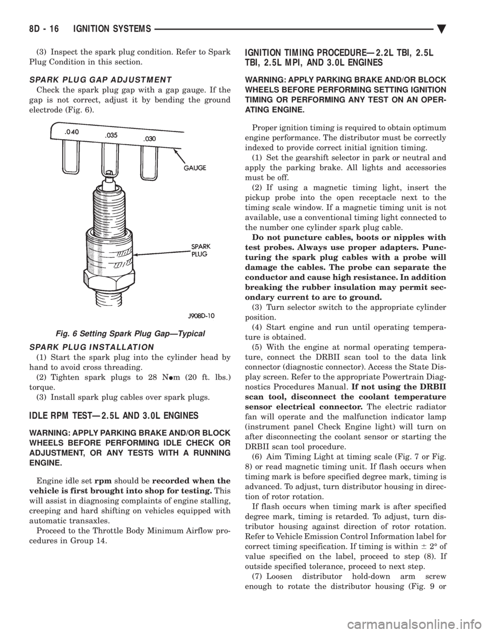
Check the spark plug gap with a gap gauge. If the
gap is not correct, adjust it by bending the ground
electrode (Fig. 6).
SPARK PLUG INSTALLATION
(1) Start the spark plug into the cylinder head by
hand to avoid cross threading. (2) Tighten spark plugs to 28 N Im (20 ft. lbs.)
torque. (3) Install spark plug cables over spark plugs.
IDLE RPM TESTÐ2.5L AND 3.0L ENGINES
WARNING: APPLY PARKING BRAKE AND/OR BLOCK
WHEELS BEFORE PERFORMING IDLE CHECK OR
ADJUSTMENT, OR ANY TESTS WITH A RUNNING
ENGINE.
Engine idle set rpmshould be recorded when the
vehicle is first brought into shop for testing. This
will assist in diagnosing complaints of engine stalling,
creeping and hard shifting on vehicles equipped with
automatic transaxles. Proceed to the Throttle Body Minimum Airflow pro-
cedures in Group 14.
IGNITION TIMING PROCEDUREÐ2.2L TBI, 2.5L
TBI, 2.5L MPI, AND 3.0L ENGINES
WARNING: APPLY PARKING BRAKE AND/OR BLOCK
WHEELS BEFORE PERFORMING SETTING IGNITION
TIMING OR PERFORMING ANY TEST ON AN OPER-
ATING ENGINE.
Proper ignition timing is required to obtain optimum
engine performance. The distributor must be correctly
indexed to provide correct initial ignition timing. (1) Set the gearshift selector in park or neutral and
apply the parking brake. All lights and accessories
must be off. (2) If using a magnetic timing light, insert the
pickup probe into the open receptacle next to the
timing scale window. If a magnetic timing unit is not
available, use a conventional timing light connected to
the number one cylinder spark plug cable. Do not puncture cables, boots or nipples with
test probes. Always use proper adapters. Punc-
turing the spark plug cables with a probe will
damage the cables. The probe can separate the
conductor and cause high resistance. In addition
breaking the rubber insulation may permit sec-
ondary current to arc to ground. (3) Turn selector switch to the appropriate cylinder
position. (4) Start engine and run until operating tempera-
ture is obtained. (5) With the engine at normal operating tempera-
ture, connect the DRBII scan tool to the data link
connector (diagnostic connector). Access the State Dis-
play screen. Refer to the appropriate Powertrain Diag-
nostics Procedures Manual. If not using the DRBII
scan tool, disconnect the coolant temperature
sensor electrical connector. The electric radiator
fan will operate and the malfunction indicator lamp
(instrument panel Check Engine light) will turn on
after disconnecting the coolant sensor or starting the
DRBII scan tool procedure. (6) Aim Timing Light at timing scale (Fig. 7 or Fig.
8) or read magnetic timing unit. If flash occurs when
timing mark is before specified degree mark, timing is
advanced. To adjust, turn distributor housing in direc-
tion of rotor rotation. If flash occurs when timing mark is after specified
degree mark, timing is retarded. To adjust, turn dis-
tributor housing against direction of rotor rotation.
Refer to Vehicle Emission Control Information label for
correct timing specification. If timing is within 62É of
value specified on the label, proceed to step (8). If
outside specified tolerance, proceed to next step. (7) Loosen distributor hold-down arm screw
enough to rotate the distributor housing (Fig. 9 or
Fig. 6 Setting Spark Plug GapÐTypical
8D - 16 IGNITION SYSTEMS Ä
Page 459 of 2438
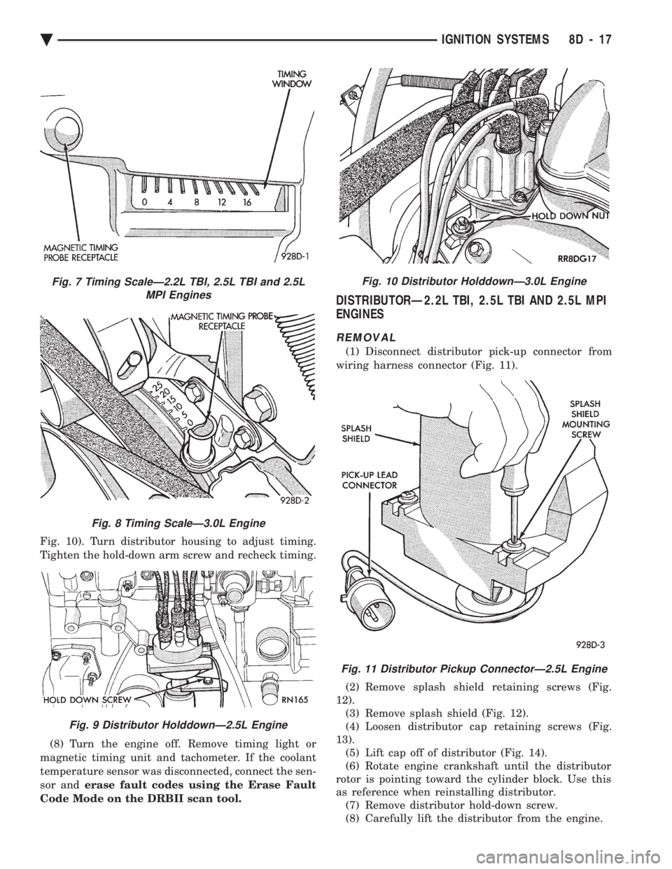
Fig. 10). Turn distributor housing to adjust timing.
Tighten the hold-down arm screw and recheck timing.
(8) Turn the engine off. Remove timing light or
magnetic timing unit and tachometer. If the coolant
temperature sensor was disconnected, connect the sen-
sor and erase fault codes using the Erase Fault
Code Mode on the DRBII scan tool.
DISTRIBUTORÐ2.2L TBI, 2.5L TBI AND 2.5L MPI
ENGINES
REMOVAL
(1) Disconnect distributor pick-up connector from
wiring harness connector (Fig. 11).
(2) Remove splash shield retaining screws (Fig.
12). (3) Remove splash shield (Fig. 12).
(4) Loosen distributor cap retaining screws (Fig.
13). (5) Lift cap off of distributor (Fig. 14).
(6) Rotate engine crankshaft until the distributor
rotor is pointing toward the cylinder block. Use this
as reference when reinstalling distributor. (7) Remove distributor hold-down screw.
(8) Carefully lift the distributor from the engine.
Fig. 10 Distributor HolddownÐ3.0L Engine
Fig. 11 Distributor Pickup ConnectorÐ2.5L Engine
Fig. 7 Timing ScaleÐ2.2L TBI, 2.5L TBI and 2.5L MPI Engines
Fig. 8 Timing ScaleÐ3.0L Engine
Fig. 9 Distributor HolddownÐ2.5L Engine
Ä IGNITION SYSTEMS 8D - 17
Page 468 of 2438
tance. The cables provide suppression of radio fre-
quency emissions from the ignition system.Check the spark plug cable connections for good
contact at the coil and distributor cap towers and at
the spark plugs. Terminals should be fully seated.
The nipples and spark plug covers should be in good
condition. Nipples should fit tightly on the coil and
distributor cap towers and spark plug cover should
fit tight around spark plug insulators. Loose cable
connections can cause ignition malfunctions by per-
mitting water to enter the towers, corroding, and in-
creasing resistance.
SPARK PLUGS
The 2.2L Turbo III, 3.3L and 3.8L engines use re-
sistor spark plugs. They have resistance values of
6,000 to 20,000 ohms when checked with at least a
1000 volt tester. Remove the spark plugs and examine them for
burned electrodes and fouled, cracked or broken por-
celain insulators. Keep plugs arranged in the order
in which they were removed from the engine. An iso-
lated plug displaying an abnormal condition indi-
cates that a problem exists in the corresponding
cylinder. Replace spark plugs at the intervals recom-
mended in Group O. Spark plugs that have low milage may be cleaned
and reused if not otherwise defective. Refer to the
Spark Plug Condition section of this group. After
cleaning, file the center electrode flat with a small
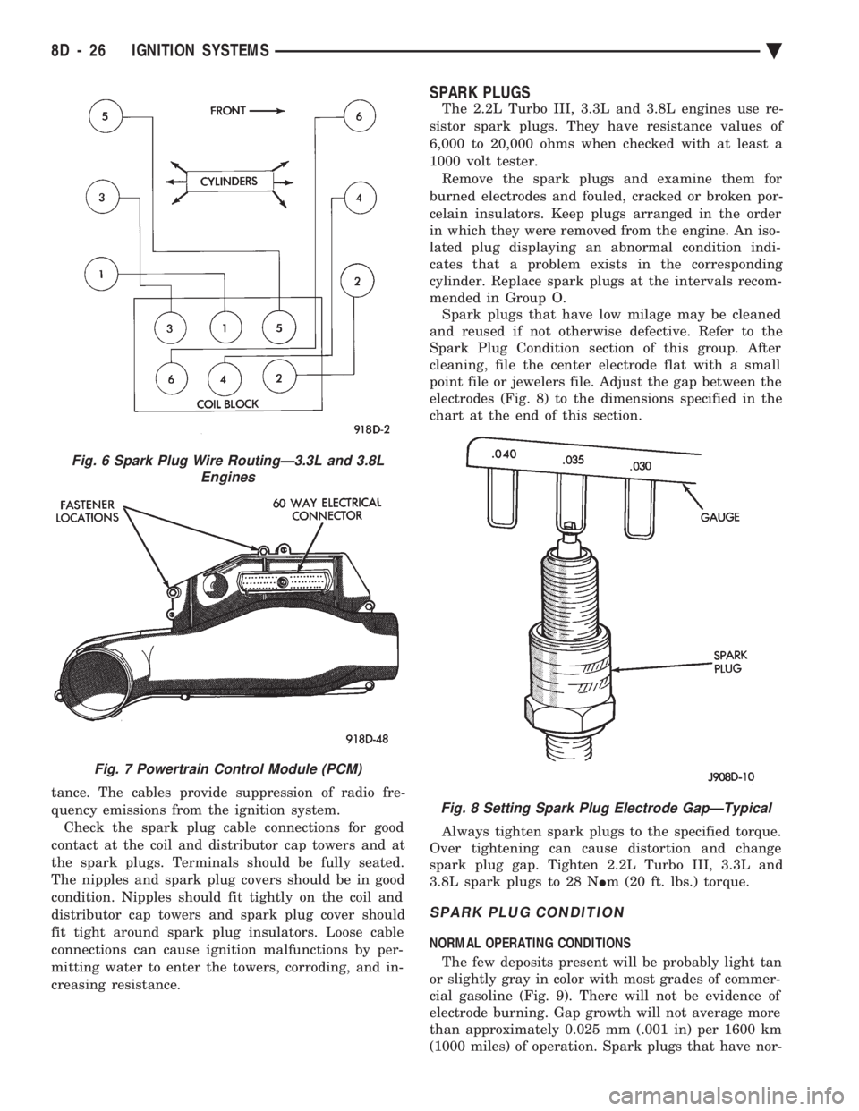
point file or jewelers file. Adjust the gap between the
electrodes (Fig. 8) to the dimensions specified in the
chart at the end of this section.
Always tighten spark plugs to the specified torque.
Over tightening can cause distortion and change
spark plug gap. Tighten 2.2L Turbo III, 3.3L and
3.8L spark plugs to 28 N Im (20 ft. lbs.) torque.
SPARK PLUG CONDITION
NORMAL OPERATING CONDITIONS
The few deposits present will be probably light tan
or slightly gray in color with most grades of commer-
cial gasoline (Fig. 9). There will not be evidence of
electrode burning. Gap growth will not average more
than approximately 0.025 mm (.001 in) per 1600 km
(1000 miles) of operation. Spark plugs that have nor-
Fig. 6 Spark Plug Wire RoutingÐ3.3L and 3.8L Engines
Fig. 7 Powertrain Control Module (PCM)
Fig. 8 Setting Spark Plug Electrode GapÐTypical
8D - 26 IGNITION SYSTEMS Ä
Page 479 of 2438
FAILURE TO START TEST
This no-start test checks the camshaft position sen-
sor and crankshaft position sensor. The powertrain control module (PCM) supplies 8.0
volts to the camshaft position sensor and crankshaft
position sensor through one circuit. If the 8.0-volt
supply circuit shorts to ground, neither sensor will
produce a signal (output voltage to the PCM). When the ignition key is turned and left in the On
position , the PCM automatically energizes the auto shutdown (ASD) relay. However, the PCM de-energizes
the relay within one second because it has not received
a crankshaft position sensor signal indicating engine
rotation.
During cranking, the ASD relay will not energize
until the PCM receives a crankshaft signal. Secondly,
the ASD relay remains energized only if the PCM
senses a camshaft position sensor signal immediately
after detecting the crankshaft position sensor signal. (1) Check battery voltage. Voltage should approxi-
mately 12.66 volts or higher to perform failure to start
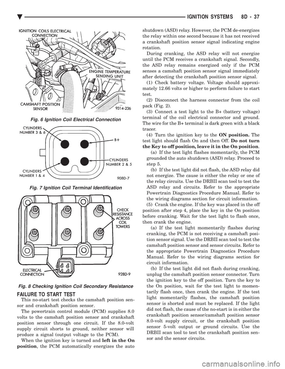
test. (2) Disconnect the harness connector from the coil
pack (Fig. 2). (3) Connect a test light to the B+ (battery voltage)
terminal of the coil electrical connector and ground.
The wire for the B+ terminal is dark green with a black
tracer. (4) Turn the ignition key to the ON position.The
test light should flash On and then Off. Do not turn
the Key to off position, leave it in the On position .
(a) If the test light flashes momentarily, the PCM
grounded the auto shutdown (ASD) relay. Proceed to
step 5. (b) If the test light did not flash, the ASD relay did
not energize. The cause is either the relay or one of
the relay circuits. Use the DRBII scan tool to test the
ASD relay and circuits. Refer to the appropriate
Powertrain Diagnostics Procedure Manual. Refer to
the wiring diagrams section for circuit information.
(5) Crank the engine. If the key was placed in the off
position after step 4, place the key in the On position
before cranking. Wait for the test light to flash once,
then crank the engine. (a) If the test light momentarily flashes during
cranking, the PCM is not receiving a camshaft posi-
tion sensor signal. Use the DRBII scan tool to test the
camshaft position sensor and sensor circuits. Refer to
the appropriate Powertrain Diagnostics Procedure
Manual. Refer to the wiring diagrams section for
circuit information. (b) If the test light did not flash during cranking,
unplug the camshaft position sensor connector. Turn
the ignition key to the off position. Turn the key to
the On position, wait for the test light to momen-
tarily flash once, then crank the engine. If the test
light momentarily flashes, the camshaft position
sensor is shorted and must be replaced. If the light
did not flash, the cause of the no-start is in either the
crankshaft position sensor/camshaft position sensor
8.0-volt supply circuit, or the crankshaft position
sensor 5-volt output or ground circuits. Use the
DRBII scan tool to test the crankshaft position sen-
sor and the sensor circuits.
Fig. 6 Ignition Coil Electrical Connection
Fig. 7 Ignition Coil Terminal Identification
Fig. 8 Checking Ignition Coil Secondary Resistance
Ä IGNITION SYSTEMS 8D - 37
Page 483 of 2438
(2) With engine running, move test probe along
entire length of all cables (approximately 0 to 1/8
inch gap). If punctures or cracks are present there
will be a noticeable spark jump from the faulty area
to the probe. Cracked, leaking or faulty cables should
be replaced. Use the following procedure when removing the
high tension cable from the spark plug. First, remove
the cable from the retaining bracket. Then grasp the
terminal as close as possible to the spark plug. Ro-
tate the cover (boot) slightly and pull straight back.
Do not use pliers and do not pull the cable at an
angle. Doing so will damage the insulation, cable
terminal or the spark plug insulator. Wipe spark
plug insulator clean before reinstalling cable
and cover. Resistance cables are identified by the words Elec-
tronic Suppression .
Use an ohmmeter to check cables for opens, loose
terminals or high resistance. (a) Remove cable from spark plug.
(b) Remove cable from the coil tower.
(c) Connect the ohmmeter between spark plug
end terminal and the coil end terminal. Resistance
should be within tolerance shown in the cable re-
sistance chart. If resistance is not within tolerance,
replace cable assembly. Test all spark plug cables
in same manner.
SPARK PLUG SERVICE
When replacing the spark plug cables, route the ca-
bles correctly and secure them in the appropriate re-
tainers. Incorrectly routed cables can cause the radio
to reproduce ignition noise. It can also cause cross ig-
nition of the spark plugs or short circuit the cables to
ground.
SPARK PLUG REMOVAL
Always remove cables by grasping at boot, rotating
the boot 1/2 turn, and pulling straight back in a
steady motion. (1) Prior to removing the spark plug spray com-
pressed air around the spark plug hole and the area
around the spark plug. (2) Remove the spark plug using a quality socket
with a rubber or foam insert. (3) Inspect the spark plug condition. Refer to
Spark Plug Condition in this section.
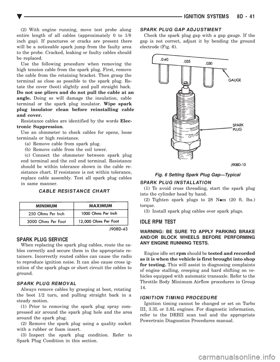
SPARK PLUG GAP ADJUSTMENT
Check the spark plug gap with a gap gauge. If the
gap is not correct, adjust it by bending the ground
electrode (Fig. 6).
SPARK PLUG INSTALLATION
(1) To avoid cross threading, start the spark plug
into the cylinder head by hand. (2) Tighten spark plugs to 28 N Im (20 ft. lbs.)
torque. (3) Install spark plug cables over spark plugs.
IDLE RPM TEST
WARNING: BE SURE TO APPLY PARKING BRAKE
AND/OR BLOCK WHEELS BEFORE PERFORMING
ANY ENGINE RUNNING TESTS.
Engine idle set rpmshould be tested and recorded
as it is when the vehicle is first brought into shop
for testing. This will assist in diagnosing complaints
of engine stalling, creeping and hard shifting on ve-
hicles equipped with automatic transaxle. Refer to the
Throttle Body Minimum Airflow procedures in Group
14.
IGNITION TIMING PROCEDURE
Ignition timing cannot be changed or set on Turbo
III, 3.3L or 3.8L engines. For diagnostic information,
refer to the DRBII scan tool and the appropriate
Powertrain Diagnostics Procedures manual.
CABLE RESISTANCE CHART
Fig. 6 Setting Spark Plug GapÐTypical
Ä IGNITION SYSTEMS 8D - 41
Page 494 of 2438
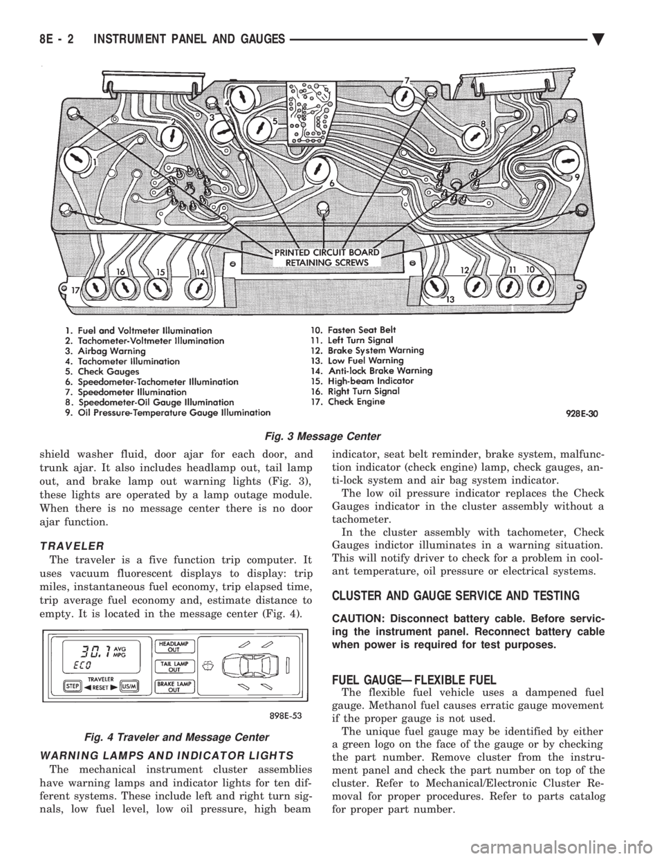
shield washer fluid, door ajar for each door, and
trunk ajar. It also includes headlamp out, tail lamp
out, and brake lamp out warning lights (Fig. 3),
these lights are operated by a lamp outage module.
When there is no message center there is no door
ajar function.
TRAVELER
The traveler is a five function trip computer. It
uses vacuum fluorescent displays to display: trip
miles, instantaneous fuel economy, trip elapsed time,
trip average fuel economy and, estimate distance to
empty. It is located in the message center (Fig. 4).
WARNING LAMPS AND INDICATOR LIGHTS
The mechanical instrument cluster assemblies
have warning lamps and indicator lights for ten dif-
ferent systems. These include left and right turn sig-
nals, low fuel level, low oil pressure, high beam indicator, seat belt reminder, brake system, malfunc-
tion indicator (check engine) lamp, check gauges, an-
ti-lock system and air bag system indicator. The low oil pressure indicator replaces the Check
Gauges indicator in the cluster assembly without a
tachometer. In the cluster assembly with tachometer, Check
Gauges indictor illuminates in a warning situation.
This will notify driver to check for a problem in cool-
ant temperature, oil pressure or electrical systems.
CLUSTER AND GAUGE SERVICE AND TESTING
CAUTION: Disconnect battery cable. Before servic-
ing the instrument panel. Reconnect battery cable
when power is required for test purposes.
FUEL GAUGEÐFLEXIBLE FUEL
The flexible fuel vehicle uses a dampened fuel
gauge. Methanol fuel causes erratic gauge movement
if the proper gauge is not used. The unique fuel gauge may be identified by either
a green logo on the face of the gauge or by checking
the part number. Remove cluster from the instru-
ment panel and check the part number on top of the
cluster. Refer to Mechanical/Electronic Cluster Re-
moval for proper procedures. Refer to parts catalog
for proper part number.
Fig. 3 Message Center
Fig. 4 Traveler and Message Center
8E - 2 INSTRUMENT PANEL AND GAUGES Ä
Page 495 of 2438
SENDING UNIT TEST
When a problem occurs with a cluster gauge, be-
fore disassembling the cluster to check the gauge,
check for a defective sending unit or wiring. (1) Sending units and wiring can be checked by
grounding the connector leads, at the sending unit,
in the vehicle. (2) With the ignition in the ON position; a
grounded input will cause the oil, fuel or tempera-
ture gauge to read at or above maximum.
LOW OIL PRESSURE/CHECK GAUGES WARNING LAMP TEST
The low oil pressure/check gauges warning lamp
will illuminate when the ignition key is turned to
the ON position without starting the vehicle. In the cluster assembly without tachometer, the
low oil pressure lamp will illuminate if the engine oil
pressure drops below a safe oil pressure level. In the cluster assembly with tachometer, the Check
Gauges warning lamp illuminates when there is a
problem in oil pressure level, high engine tempera-
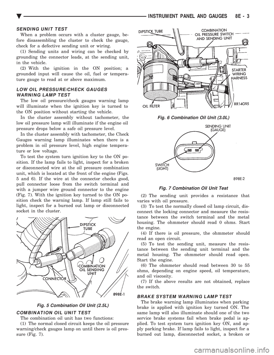
ture or low voltage. To test the system turn ignition key to the ON po-
sition. If the lamp fails to light, inspect for a broken
or disconnected wire at the oil pressure combination
unit, which is located at the front of the engine (Figs.
5 and 6). If the wire at the connector checks good,
pull connector loose from the switch terminal and
with a jumper wire ground connector to the engine
(Fig. 7). With the ignition key turned to the ON po-
sition check the warning lamp. If lamp still fails to
light, inspect for a burned out lamp or disconnected
socket in the cluster.
COMBINATION OIL UNIT TEST
The combination oil unit has two functions:
(1) The normal closed circuit keeps the oil pressure
warning/check gauges lamp on until there is oil pres-
sure (Fig. 7). (2) The sending unit provides a resistance that
varies with oil pressure. (3) To test the normally closed oil lamp circuit, dis-
connect the locking connector and measure the resis-
tance between the switch terminal and the metal
housing. The ohmmeter should read 0 ohms. Start
the engine. (4) If there is oil pressure, the ohmmeter should
read an open circuit. (5) To test the sending unit, measure the resis-
tance between the sending unit terminal and the
metal housing. The ohmmeter should read open.
Start the engine. (6) The ohmmeter should read between 30 to 55
ohms, depending on engine speed, oil temperature,
and oil viscosity. (7) If the above results are not obtained, replace
the switch.
BRAKE SYSTEM WARNING LAMP TEST
The brake warning lamp illuminates when parking
brake is applied with ignition key turned ON. The
same lamp will also illuminate should one of the two
service brake systems fail when brake pedal is ap-
plied. To test system turn ignition key ON, and ap-
ply parking brake. If lamp fails to light, inspect for a
burned out lamp, disconnected socket, a broken orFig. 5 Combination Oil Unit (2.5L)
Fig. 6 Combination Oil Unit (3.0L)
Fig. 7 Combination Oil Unit Test
Ä INSTRUMENT PANEL AND GAUGES 8E - 3