fuse diagram CHEVROLET DYNASTY 1993 Service Manual
[x] Cancel search | Manufacturer: CHEVROLET, Model Year: 1993, Model line: DYNASTY, Model: CHEVROLET DYNASTY 1993Pages: 2438, PDF Size: 74.98 MB
Page 30 of 2438
GROUP TAB LOCATOR
GENERAL INFORMATION
FUSE CHARTS AND RELAY BANKS
WIRING AND COMPONENT
IDENTIFICATION
SPLICE LOCATIONS
AA-C, D, P WIRING DIAGRAMS
AC-C, D/AY-C WIRING DIAGRAMS
AG-D, AJ-C WIRING DIAGRAMS
AP-P, D WIRING DIAGRAMS
Service Manual Comment Forms (Rear of Manual)
Page 381 of 2438
IGNITION OFF DRAW (IOD)
GENERAL INFORMATION
A normal electrical system will draw from 5 to 30
milliamperes from the battery. This is with the ignition
in the OFF position, and all non-ignition controlled cir-
cuits in proper working order. The amount of IOD will
depend on body model and electrical components. A ve-
hicle that has not been operated for an extended period
of approximately 20 days may discharge the battery to
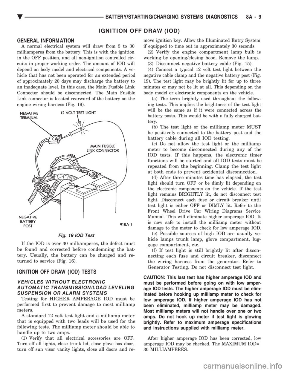
an inadequate level. In this case, the Main Fusible Link
Connector should be disconnected. The Main Fusible
Link connector is located rearward of the battery on the
engine wiring harness (Fig. 19).
If the IOD is over 30 milliamperes, the defect must
be found and corrected before condemning the bat-
tery. Usually, the battery can be charged and re-
turned to service (Fig. 16).
IGNITION OFF DRAW (IOD) TESTS
VEHICLES WITHOUT ELECTRONIC AUTOMATIC TRANSMISSION/LOAD LEVELINGSUSPENSION OR ALARM SYSTEMS
Testing for HIGHER AMPERAGE IOD must be
performed first to prevent damage to most milliamp
meters. A standard 12 volt test light and a milliamp meter
that is equipped with two leads will be used for the
following tests. The milliamp meter should be able to
handle up to two amps.
(1) Verify that all electrical accessories are OFF.
Turn off all lights, close trunk lid, close glove box door,
turn off sun visor vanity lights, close all doors and re- move ignition key. Allow the Illuminated Entry System
if equipped to time out in approximately 30 seconds.
(2) Verify the engine compartment lamp bulb is
working by opening/closing hood. Remove the lamp. (3) Disconnect negative battery cable (Fig. 15).
(4) Connect a typical 12 volt test light between the
negative cable clamp and the negative battery post (Fig.
19). The test light may be brightly lit for up to three
minutes or may not be lit at all. This depending on the
body model or electronic components on the vehicle. (a) The term brightly used throughout the follow-
ing tests. This implies the brightness of the test light
will be the same as if it were connected across the
battery posts. This would be with a fully charged bat-
tery.
(b) The test light or the milliamp meter MUST
be positively connected to the battery post and the
battery cable during all IOD testing. (c) Do not allow the test light or the milliamp
meter to become disconnected during any of the
IOD tests. If this happens, the electronic timer
functions will be started and all IOD tests must be
repeated from the beginning. Clamp the test light
at both ends to prevent accidental disconnection.
(d) After three minutes time has elapsed, the test
light should turn OFF or be dimly lit depending on
the electronic components on the vehicle. If the test
light remains BRIGHTLY lit, do not disconnect test
light. Disconnect each fuse or circuit breaker until
test light is either OFF or DIMLY lit. Refer to the
Front Wheel Drive Car Wiring Diagrams Service
Manual. This will eliminate higher amperage IOD. It
is now safe to install the milliamp meter without
damage to the meter to check for low amperage IOD.
(e) Possible sources of high IOD are usually ve-
hicle lamps trunk lamp, glove compartment, lug-
gage compartment, etc.. (f) If test light is still brightly lit after discon-
necting each fuse and circuit breaker, disconnect
the wiring harness from the generator. Refer to
Generator Testing. Do not disconnect test light.
CAUTION: This last test has higher amperage IOD and
must be performed before going on with low amper-
age IOD tests. The higher amperage IOD must be elim-
inated before hooking up milliamp meter to check for
low amperage IOD. If higher amperage IOD has not
been eliminated, milliamp meter may be damaged.
Most milliamp meters will not handle over one or two
amps. Do not hook up meter if test light is glowing
brightly. Refer to maximum amperage specifications
and instructions supplied with milliamp meter.
After higher amperage IOD has been corrected, low
amperage IOD may be checked. The MAXIMUM IOD=
30 MILLIAMPERES.
Fig. 19 IOD Test
Ä BATTERY/STARTING/CHARGING SYSTEMS DIAGNOSTICS 8A - 9
Page 520 of 2438
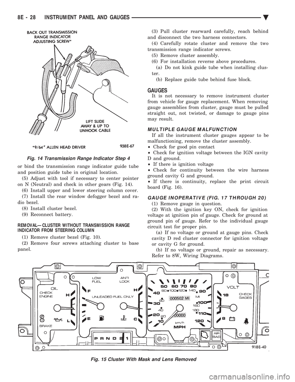
or bind the transmission range indicator guide tube
and position guide tube in original location.(5) Adjust with tool if necessary to center pointer
on N (Neutral) and check in other gears (Fig. 14). (6) Install upper and lower steering column cover.
(7) Install the rear window defogger bezel and ra-
dio bezel. (8) Install cluster bezel.
(9) Reconnect battery.
REMOVALÐCLUSTER WITHOUT TRANSMISSION RANGE
INDICATOR FROM STEERING COLUMN
(1) Remove cluster bezel (Fig. 10).
(2) Remove four screws attaching cluster to base
panel. (3) Pull cluster rearward carefully, reach behind
and disconnect the two harness connectors. (4) Carefully rotate cluster and remove the two
transmission range indicator screws. (5) Remove cluster assembly.
(6) For installation reverse above procedures. (a) Do not kink guide tube when installing clus-
ter. (b) Replace guide tube behind fuse block.
GAUGES
It is not necessary to remove instrument cluster
from vehicle for gauge replacement. When removing
gauge assemblies from cluster, gauge must be pulled
straight out, not twisted, or damage to gauge pins
may result.
MULTIPLE GAUGE MALFUNCTION
If all the instrument cluster gauges appear to be
malfunctioning, remove the cluster assembly.
² Check for good pin contact
² Check for ignition voltage between the IGN cavity
D and ground.
² If there is ignition voltage
² Check for continuity between the wire harness
ground cavity G and ground.
² If there is continuity, replace the print circuit
board (Fig. 16).
GAUGE INOPERATIVE (FIG. 17 THROUGH 20)
(1) Remove gauge in question.
(2) With the ignition key ON, check for ignition
voltage at ignition pin of gauge. Check for ground at
ground pin of gauge. Refer to the individual gauge
circuit test for proper pin. (a) If no voltage or ground at gauge pins. Check
cavity D red cluster connector for ignition voltage
or cavity G for ground. (b) If no voltage or ground, repair as necessary.
Refer to 8W, Wiring Diagrams.
Fig. 15 Cluster With Mask and Lens Removed
Fig. 14 Transmission Range Indicator Step 4
8E - 28 INSTRUMENT PANEL AND GAUGES Ä
Page 606 of 2438
Electronic vehicle speed control may be tested us-
ing two different methods. One involves use of a
DRB II. If this test method is desired, refer to the
Powertrain Diagnostic Test Procedures for charging
and vehicle speed control manual. The other test method uses a volt/ohm meter and is
described in the following tests. If any information is needed concerning wiring, re-
fer to Group 8W, Wiring Diagrams.
CAUTION: When test probing for voltage or conti-
nuity at electrical connectors, care must be taken
not to damage connector, terminals, or seals. If
these components are damaged, intermittent or
complete system failure may occur.
SERVO ELECTRICAL TESTS
WARNING: ON VEHICLES EQUIPPED WITH AIR-
BAG, SEE GROUP 8M, RESTRAINT SYSTEMS FOR
AIRBAG, STEERING WHEEL OR COLUMN RE-
MOVAL PROCEDURES.
(1) Turn ignition switch to the ON position. With
the vehicle speed control switch in the ON position,
set up a voltmeter to read battery voltage and con-
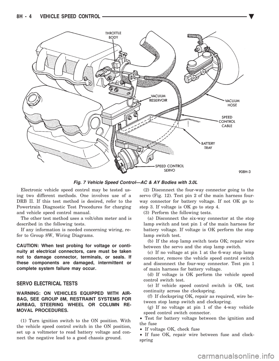
nect the negative lead to a good chassis ground. (2) Disconnect the four-way connector going to the
servo (Fig. 12). Test pin 2 of the main harness four-
way connector for battery voltage. If not OK go to
step 3. If voltage is OK go to step 4. (3) Perform the following tests.(a) Disconnect the six-way connector at the stop
lamp switch and test pin 1 of the main harness for
battery voltage. If voltage is OK perform the stop
lamp switch test. (b) If the stop lamp switch tests OK; repair wire
between the servo and the stop lamp switch. (c) If no voltage at pin 1 at the 6-way stop lamp
connector, remove the vehicle speed control switch
and disconnect the four-way connector. Test pin 1
of main harness for battery voltage. (d) If voltage is OK perform the vehicle speed
control switch test. (e) If vehicle speed control switch is OK, test
continuity across the clockspring. (f) If clockspring OK, repair as required, wire be-
tween stop lamp switch and clockspring. (g) If no voltage at pin 1 of the 4-way vehicle
speed control switch connector.
² Test for battery voltage between the ignition and
the fuse
² If voltage OK, check fuse
² If fuse OK, repair wire between fuse and clock-
spring
Fig. 7 Vehicle Speed ControlÐAC & AY Bodies with 3.0L
8H - 4 VEHICLE SPEED CONTROL Ä
Page 626 of 2438
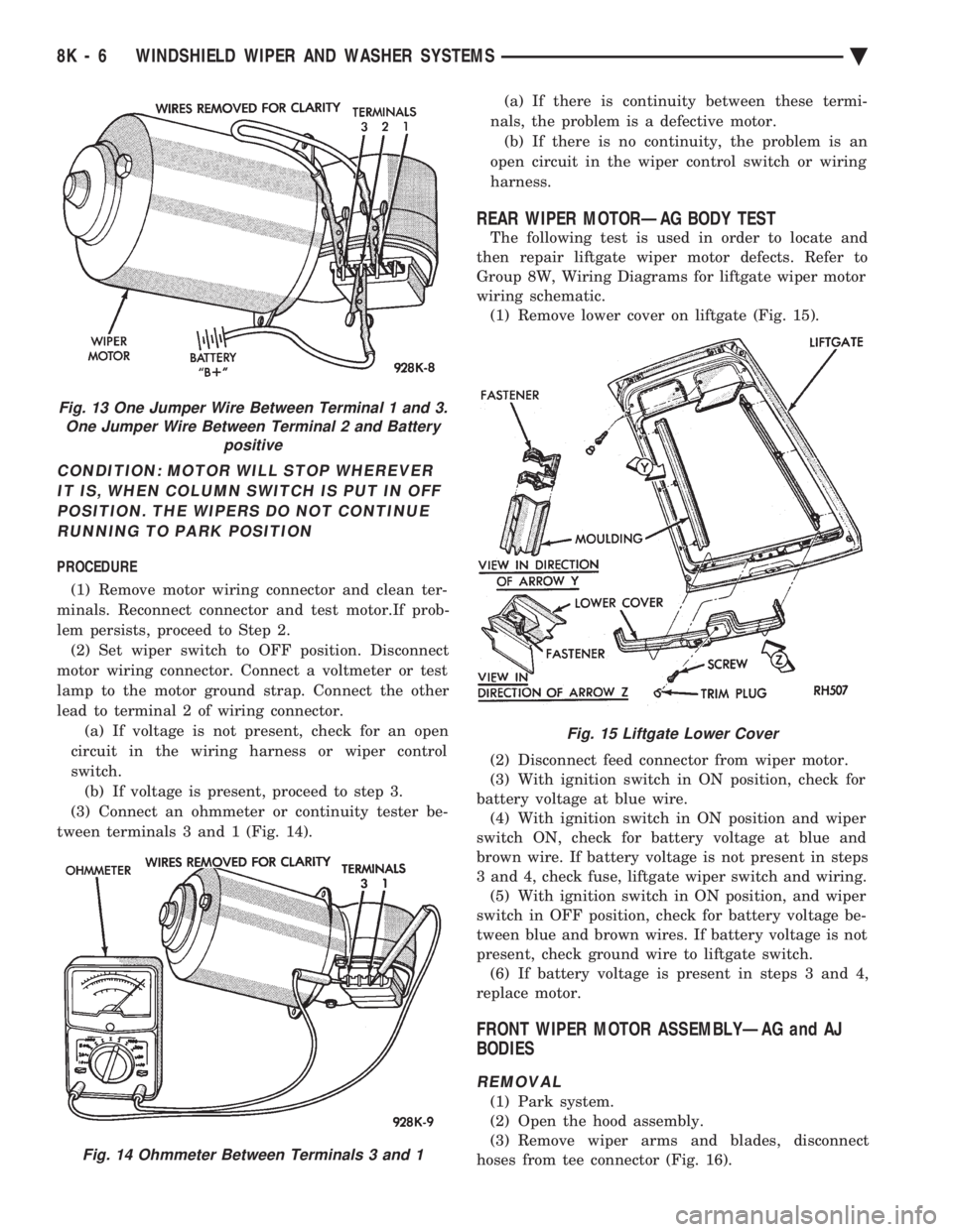
CONDITION: MOTOR WILL STOP WHEREVER IT IS, WHEN COLUMN SWITCH IS PUT IN OFFPOSITION. THE WIPERS DO NOT CONTINUERUNNING TO PARK POSITION
PROCEDURE
(1) Remove motor wiring connector and clean ter-
minals. Reconnect connector and test motor.If prob-
lem persists, proceed to Step 2. (2) Set wiper switch to OFF position. Disconnect
motor wiring connector. Connect a voltmeter or test
lamp to the motor ground strap. Connect the other
lead to terminal 2 of wiring connector. (a) If voltage is not present, check for an open
circuit in the wiring harness or wiper control
switch. (b) If voltage is present, proceed to step 3.
(3) Connect an ohmmeter or continuity tester be-
tween terminals 3 and 1 (Fig. 14). (a) If there is continuity between these termi-
nals, the problem is a defective motor. (b) If there is no continuity, the problem is an
open circuit in the wiper control switch or wiring
harness.
REAR WIPER MOTORÐAG BODY TEST
The following test is used in order to locate and
then repair liftgate wiper motor defects. Refer to
Group 8W, Wiring Diagrams for liftgate wiper motor
wiring schematic. (1) Remove lower cover on liftgate (Fig. 15).
(2) Disconnect feed connector from wiper motor.
(3) With ignition switch in ON position, check for
battery voltage at blue wire. (4) With ignition switch in ON position and wiper
switch ON, check for battery voltage at blue and
brown wire. If battery voltage is not present in steps
3 and 4, check fuse, liftgate wiper switch and wiring. (5) With ignition switch in ON position, and wiper
switch in OFF position, check for battery voltage be-
tween blue and brown wires. If battery voltage is not
present, check ground wire to liftgate switch. (6) If battery voltage is present in steps 3 and 4,
replace motor.
FRONT WIPER MOTOR ASSEMBLYÐAG and AJ
BODIES
REMOVAL
(1) Park system.
(2) Open the hood assembly.
(3) Remove wiper arms and blades, disconnect
hoses from tee connector (Fig. 16).
Fig. 13 One Jumper Wire Between Terminal 1 and 3. One Jumper Wire Between Terminal 2 and Battery positive
Fig. 14 Ohmmeter Between Terminals 3 and 1
Fig. 15 Liftgate Lower Cover
8K - 6 WINDSHIELD WIPER AND WASHER SYSTEMS Ä
Page 643 of 2438

LAMPS
CONTENTS
page page
BULB APPLICATION TABLE ............... 38
CONCEALED HEADLAMPS ................ 27
EXTERIOR LAMP SWITCHES AND HEADLAMP ALIGNMENT ........................... 3
EXTERIOR LAMP SYSTEMS .............. 25
EXTERIOR LAMPSÐAA BODY ............. 7
EXTERIOR LAMPSÐAC BODY ............ 10 EXTERIOR LAMPSÐAG BODY
............ 14
EXTERIOR LAMPSÐAJ BODY ............ 16
EXTERIOR LAMPSÐAP BODY ............ 19
EXTERIOR LAMPSÐAY-BODY ............ 22
GENERAL INFORMATION .................. 1
ILLUMINATED ENTRY SYSTEM ........... 33
GENERAL INFORMATION
Each vehicle is equipped with lamps used for illumi-
nating and indicating purposes. A circuit must have a
good ground to be complete. Circuit ground occurs
when the lamp socket makes contact with the metal
body. On vehicles with plastic lamps, a wire between
the socket and the body makes the grounds. When changing lamp bulbs, check the socket for
corrosion. If corrosion is present, clean contacts with a
wire brush and coat the inside of the socket with
Mopar tMulti-purpose Grease or equivalent.
CAUTION: Do not touch the glass of halogen bulbs
with fingers or any possibly oily surface, reduced
bulb life will result.
BODY IDENTIFICATION
Throughout this Group, references are made to the
vehicle family or body code. To decode the vehicle
identification plates, refer to the Introduction Section
at the front of this manual.
DIAGNOSTIC PROCEDURES
Begin electrical system failure diagnosis by testing
all related fuses and circuit breakers in the fuse block
and engine compartment. When a vehicle experiences problems with the head-
lamp system, verify the condition of the battery con-
nections, charging system, headlamp bulbs, wire con-
nectors, relay, high beam dimmer switch and headlamp
switch. Refer to Wiring Diagrams manual for compo-
nent locations and circuit information.
SYMPTOM
Headlamps are dim when engine is idling of
with ignition turned OFF. Canada cars must
have lamps ON. ACTION
² Clean battery terminal clamps and posts. Refer to
Group 8B, Battery/Starter/Generator Service for
proper procedures.
² Test charging system output. Refer to Group 8A,
Battery/Starting/Charging Systems Diagnostics for
proper testing procedures.
² Test for high resistance in headlamp circuits.
² Defective headlamp bulb.
SYMPTOM
Bulbs burn out frequently.
ACTION
² Test charging system output. Refer to Group 8A,
Battery/Starting/Charging Systems Diagnostics for
proper testing procedures.
² Check for loose or corroded connector terminals or
splices in headlamp circuits. Refer to Wiring Diagrams
manual for component and splice locations.
SYMPTOM
Headlamps are dim with engine running above
idle. Canada cars must have lamps ON.
ACTION
² Test charging system output. Refer to Group 8A,
Battery/Starting/Charging Systems Diagnostics for
proper testing procedures.
² Test for high resistance in headlamp circuits.
² Defective headlamp bulb.
SYMPTOM
Headlamps flash randomly.
ACTION
² Test for poor circuit ground.
² Test for high resistance in headlamp circuits.
Ä LAMPS 8L - 1
Page 644 of 2438
² Test condition of headlamp relay.
² Check for loose or corroded connector terminals or
splices in headlamp circuits. Refer to Wiring Dia-
grams manual for component and splice locations.
SYMPTOM
Headlamps do not illuminate.
ACTION
² Test for voltage at headlamp bulbs connectors.
² Test headlamp relay.
² Test headlamp switch.
² Test high-beam headlamp dimmer switch.
² Check for loose or corroded connector terminals or
splices in headlamp circuits. Refer to Wiring Dia-
grams manual for component and splice locations.
FOG LAMP DIAGNOSIS
The fog lamp system receives voltage from the
headlamp relay when the low-beam headlamps are turned ON. The high-beam headlamp dimmer switch
when actuated cancels out voltage feed to the fog
lamp circuit. The fog lamp circuit is protected by a
20 amp fuse located in the fuse panel. Refer to Wir-
ing Diagrams manual for component location and cir-
cuit information.
SYMPTOM
Fog lamps do not illuminate.
ACTION
² Test fog lamp bulb.
² Test for voltage at fog lamp connector.
² Test for proper fog lamp ground.
² Test circuit fuse.
² Test fog lamp switch.
² Test high-beam headlamp dimmer switch.
² Test headlamp relay.
² Test for open circuit in wire harness.
8L - 2 LAMPS Ä
Page 692 of 2438
(6) Steps (3, 4 or 5) above will confirm system op-
eration. Indicator light illumination means that
there is power available at the output of the relay
only, and does not necessarily verify system opera-
tion. (7) If turning the switch ON produced no distinct
current draw on the ammeter the problem should be
isolated in the following manner: (a) Confirm the ignition switch is ON.
(b) Ensure that the heated rear glass feed wire is
connected to the terminal or pigtail and that the
ground wire is in fact grounded. (c) Ensure that the fusible link and control cir-
cuit fuse is operational and all electrical connec-
tions are secure.
(8) When the above steps have been completed and
the system is still inoperative, one or more of the fol-
lowing is defective: (a) Control switch/timer relay module.
(b) All rear window grid lines would have to be
broken or one of the feed wires are not connected
for the system to be inoperative.
(9) If turning the switch ON produces severe volt-
meter deflection, the circuit should be closely
checked for a shorting condition. (10) If the system operation has been verified but
indicator lamp does not light, replace the switch. (11) For detailed wiring information, refer to group
8W, Wiring Diagrams.
GRID TEST
The horizontal grid lines and vertical bus bar lines
printed and fired on inside surface of rear window
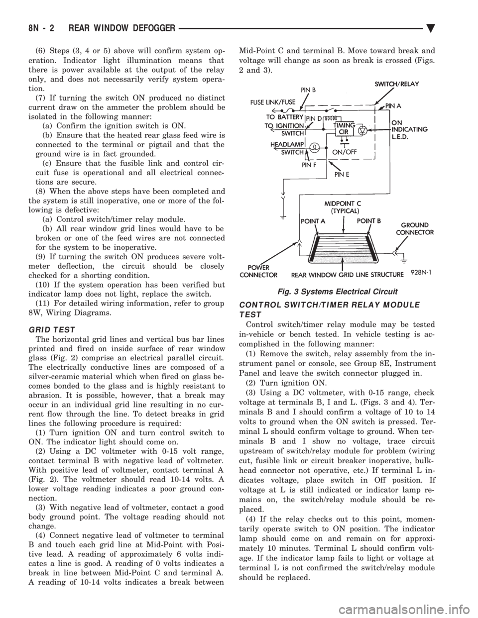
glass (Fig. 2) comprise an electrical parallel circuit.
The electrically conductive lines are composed of a
silver-ceramic material which when fired on glass be-
comes bonded to the glass and is highly resistant to
abrasion. It is possible, however, that a break may
occur in an individual grid line resulting in no cur-
rent flow through the line. To detect breaks in grid
lines the following procedure is required: (1) Turn ignition ON and turn control switch to
ON. The indicator light should come on. (2) Using a DC voltmeter with 0-15 volt range,
contact terminal B with negative lead of voltmeter.
With positive lead of voltmeter, contact terminal A
(Fig. 2). The voltmeter should read 10-14 volts. A
lower voltage reading indicates a poor ground con-
nection. (3) With negative lead of voltmeter, contact a good
body ground point. The voltage reading should not
change. (4) Connect negative lead of voltmeter to terminal
B and touch each grid line at Mid-Point with Posi-
tive lead. A reading of approximately 6 volts indi-
cates a line is good. A reading of 0 volts indicates a
break in line between Mid-Point C and terminal A.
A reading of 10-14 volts indicates a break between Mid-Point C and terminal B. Move toward break and
voltage will change as soon as break is crossed (Figs.
2 and 3).
CONTROL SWITCH/TIMER RELAY MODULE TEST
Control switch/timer relay module may be tested
in-vehicle or bench tested. In vehicle testing is ac-
complished in the following manner: (1) Remove the switch, relay assembly from the in-
strument panel or console, see Group 8E, Instrument
Panel and leave the switch connector plugged in. (2) Turn ignition ON.
(3) Using a DC voltmeter, with 0-15 range, check
voltage at terminals B, I and L. (Figs. 3 and 4). Ter-
minals B and I should confirm a voltage of 10 to 14
volts to ground when the ON switch is pressed. Ter-
minal L should confirm voltage to ground. When ter-
minals B and I show no voltage, trace circuit
upstream of switch/relay module for problem (wiring
cut, fusible link or circuit breaker inoperative, bulk-
head connector not operative, etc.) If terminal L in-
dicates voltage, place switch in Off position. If
voltage at L is still indicated or indicator lamp re-
mains on, the switch/relay module should be re-
placed. (4) If the relay checks out to this point, momen-
tarily operate switch to ON position. The indicator
lamp should come on and remain on for approxi-
mately 10 minutes. Terminal L should confirm volt-
age. If the indicator lamp fails to light or voltage at
terminal L is not confirmed the switch/relay module
should be replaced.
Fig. 3 Systems Electrical Circuit
8N - 2 REAR WINDOW DEFOGGER Ä
Page 727 of 2438
POWER WINDOWS
CONTENTS
page page
BENCH REPAIR OF REGULATOR AND MOTOR CONVENTIONAL REGULATORS .......... 5
GEAR AND PINION REPLACEMENT AND LUBRICATION ....................... 3
GENERAL INFORMATION .................. 1
MOTOR REPLACEMENT ................... 7
MOTOR REPLACEMENT CONVENTIONAL REGULATORS ....................... 3
MOTOR REPLACEMENTÐFLEX DRIVE REGULATORS ......................... 5 POWER WINDOW CABLE HOUSING/MOTOR RE-
PLACEMENTÐAC and AY BODIES ........ 7
QUARTER WINDOW MOTOR REPLACEMENTÐ AJ BODY ............................. 9
QUARTER WINDOW REPLACEMENTÐ AJ BODY ............................. 8
WINDOW LIFT MOTOR TEST .............. 1
WINDOW LIFT SWITCH TEST .............. 1
WIRING VOLTAGE TEST .................. 1
GENERAL INFORMATION
Front and rear door window lift motors are of the
permanent magnet type. A positive and negative bat-
tery connection to either of the two motor terminals
will cause the motor to rotate in one direction. Re-
versing current through these same two connections
will cause the motor to rotate in the opposite direc-
tion. Each individual motor is grounded through the
master switch by a black wire attached to the left
cowl panel. It is necessary that the window be free to slide up
and down in the glass channels or tubes and tracks.
If the window is not free to move up and down, the
window lift motor will not be able to move the glass. To determine if the glass is free is to disconnect the
regulator from the glass lift plate, and slide the win-
dow up and down by hand. For conventional arm-sec-
tor regulators, after the lift plate is detached from
the glass, it will slide off the regulator drive arm.
Flex-drive regulators may be detached the same way
or by removing one screw holding the flex rack to the
lift plate drive arm.
WIRING VOLTAGE TEST
The following wiring test determines whether or
not voltage is continuous through the body harness
to switch. After removing switch for testing purposes, care-
fully separate multiple terminal block on wiring har-
ness from switch body. With ignition switch ON
connect one lead of test light to black (or gray) wire
terminal and touch other test light lead to tan wire
terminal. If the test light comes on, the wiring cir-
cuit between the battery and switch is functional. If
light does not come on, check 30 amp main fuse (cir- cuit breaker) or for a broken wire. For wiring, spe-
cific connector type and location, refer to Group 8W,
Wiring Diagrams.
WINDOW LIFT SWITCH TEST
For switch testing, remove the switch from its
mounting. Using an ohmmeter, refer to Window
Switch Continuity Charts to determine if continuity
is correct. If the results are not obtained, replace the
switch. AC and AY Bodies are equipped with an Auto-
Down feature. This feature allows the operator to
lower the driver's window without having to hold the
switch in the down position. The Auto-Down feature
can be activated by pressing the down switch past
the first detent (Stop). To test the auto-down feature, operate the window
in the normal up and down mode. If the window
works correctly in the normal mode, but not in the
auto-down mode, replace the switch. To test the window switch (other than Auto-Down
mode), install a known good switch.
WINDOW LIFT MOTOR TEST
(1) Connect positive (+) lead from a test battery to
either of the two motor terminals. (2) Connect negative (-) lead from test battery to
remaining motor terminal. (3) The motor should now rotate in one direction to
either move window up or down. (a) If window happens to already be in full UP
position and motor is connected so as to rotate in
UP direction no movement will be observed. (b) Likewise, motor connected to DOWN direc-
tion rotation, no movement will be observed if win-
dow is already in full DOWN position.
Ä POWER WINDOWS 8S - 1
Page 744 of 2438
(2) The headlamps and parking lamps should turn
ON for about five seconds.
² AUTO MIRROR LED
² DARK LED
² AUTO LAMP LED
² The LED indicators blink for about 5 seconds.
² If the three indicators continue to blink consider-
ably longer than 5 seconds, then the mirror assembly
is defective. (3) The mirror should change to dim state.(a) Place shift selector in reverse (R), with igni-
tion switch ON:
² AUTO MIRROR LED indicator ON
² DARK LED indicator flashing
² Lasting about 15 seconds
(b) The mirror should slowly change to bright
state. (c) If the ignition is not turned OFF within the
15 second time period, the mirror will reset to its
previous setting.
The previous conditions are OK, the mirror is op-
erating properly. If not OK, continue with voltage tests below.
VOLTAGE TEST
To test for voltage insert voltmeter probe into wire
end of connector to contact terminal. Pin 1 ignition voltage (a) Ignition switch OFF, zero volts.
(b) Ignition switch ON, battery voltage.
Pin 2 battery voltage (a) Battery voltage at all times.
(b) No voltage, check 15 amp. fuse.
Pin 3 Ground (a) Continuity to ground.
(b) No voltage
Pin 4 Reverse over-ride (a) Ignition OFF, zero voltage.
(b) Ignition ON shift selector in Reverse (R), bat-
tery voltage. (c) Ignition ON shift selector in any position
other than Reverse (R), zero voltage.
Pin 5 Headlamp relay (a) Battery voltage at all times from headlamp
relay. (b) No battery voltage, test headlamp relay.
Pin 6 Park lamp relay (a) Ignition switch ON, battery voltage feed from
park lamp relay. (b) Ignition switch OFF, zero voltage.
(c) Ignition ON, No battery voltage test park
lamp relay.
If Voltage Test are OK, replace mirror assembly.
If not OK, refer to Wiring Diagrams manual.
8T - 8 POWER MIRRORS Ä