differential CHEVROLET DYNASTY 1993 User Guide
[x] Cancel search | Manufacturer: CHEVROLET, Model Year: 1993, Model line: DYNASTY, Model: CHEVROLET DYNASTY 1993Pages: 2438, PDF Size: 74.98 MB
Page 260 of 2438
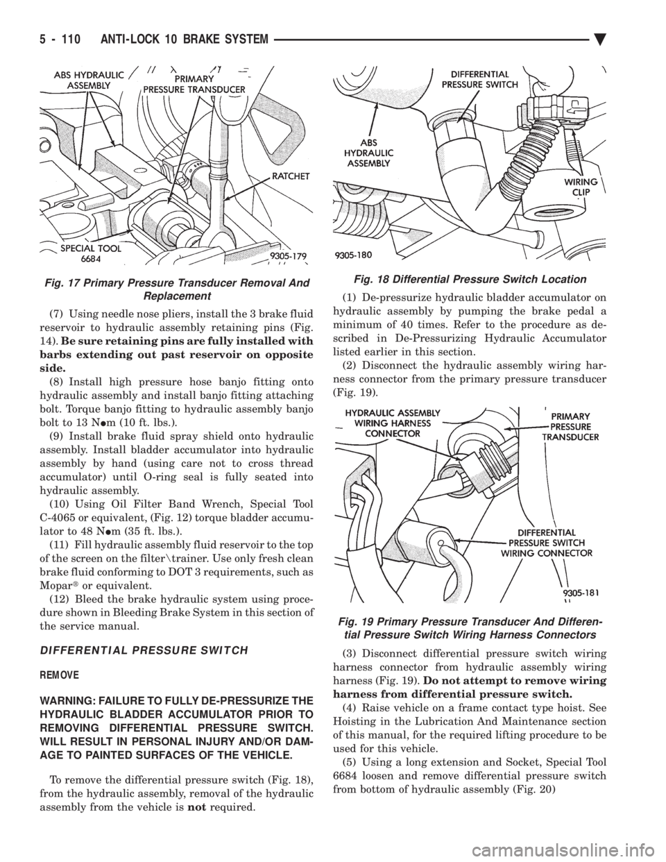
(7) Using needle nose pliers, install the 3 brake fluid
reservoir to hydraulic assembly retaining pins (Fig.
14). Be sure retaining pins are fully installed with
barbs extending out past reservoir on opposite
side. (8) Install high pressure hose banjo fitting onto
hydraulic assembly and install banjo fitting attaching
bolt. Torque banjo fitting to hydraulic assembly banjo
bolt to 13 N Im (10 ft. lbs.).
(9) Install brake fluid spray shield onto hydraulic
assembly. Install bladder accumulator into hydraulic
assembly by hand (using care not to cross thread
accumulator) until O-ring seal is fully seated into
hydraulic assembly. (10) Using Oil Filter Band Wrench, Special Tool
C-4065 or equivalent, (Fig. 12) torque bladder accumu-
lator to 48 N Im (35 ft. lbs.).
(11) Fill hydraulic assembly fluid reservoir to the top
of the screen on the filter rainer. Use only fresh clean
brake fluid conforming to DOT 3 requirements, such as
Mopar tor equivalent.
(12) Bleed the brake hydraulic system using proce-
dure shown in Bleeding Brake System in this section of
the service manual.
DIFFERENTIAL PRESSURE SWITCH
REMOVE
WARNING: FAILURE TO FULLY DE-PRESSURIZE THE
HYDRAULIC BLADDER ACCUMULATOR PRIOR TO
REMOVING DIFFERENTIAL PRESSURE SWITCH.
WILL RESULT IN PERSONAL INJURY AND/OR DAM-
AGE TO PAINTED SURFACES OF THE VEHICLE.
To remove the differential pressure switch (Fig. 18),
from the hydraulic assembly, removal of the hydraulic
assembly from the vehicle is notrequired. (1) De-pressurize hydraulic bladder accumulator on
hydraulic assembly by pumping the brake pedal a
minimum of 40 times. Refer to the procedure as de-
scribed in De-Pressurizing Hydraulic Accumulator
listed earlier in this section. (2) Disconnect the hydraulic assembly wiring har-
ness connector from the primary pressure transducer
(Fig. 19).
(3) Disconnect differential pressure switch wiring
harness connector from hydraulic assembly wiring
harness (Fig. 19). Do not attempt to remove wiring
harness from differential pressure switch. (4) Raise vehicle on a frame contact type hoist. See
Hoisting in the Lubrication And Maintenance section
of this manual, for the required lifting procedure to be
used for this vehicle. (5) Using a long extension and Socket, Special Tool
6684 loosen and remove differential pressure switch
from bottom of hydraulic assembly (Fig. 20)
Fig. 18 Differential Pressure Switch Location
Fig. 19 Primary Pressure Transducer And Differen- tial Pressure Switch Wiring Harness Connectors
Fig. 17 Primary Pressure Transducer Removal And Replacement
5 - 110 ANTI-LOCK 10 BRAKE SYSTEM Ä
Page 261 of 2438
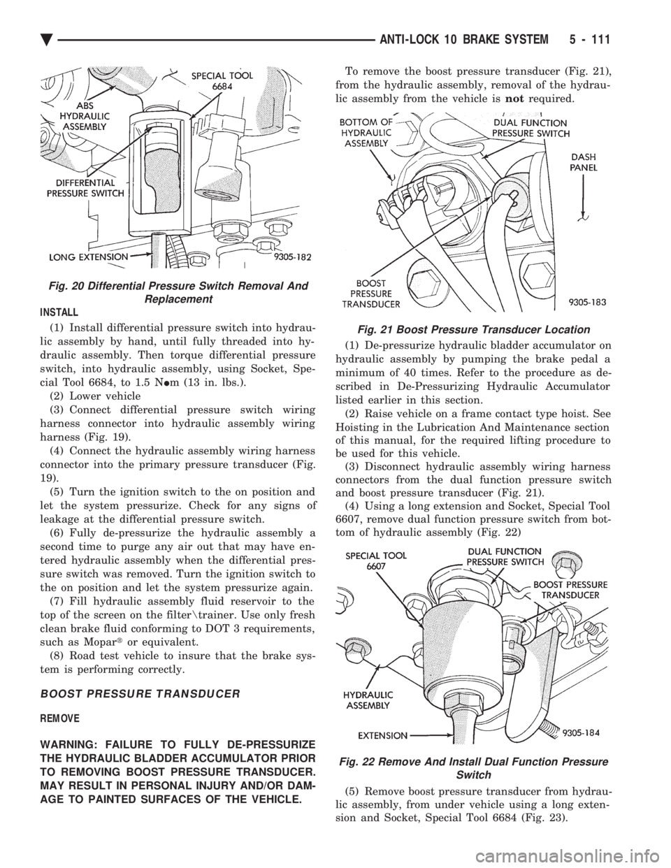
INSTALL (1) Install differential pressure switch into hydrau-
lic assembly by hand, until fully threaded into hy-
draulic assembly. Then torque differential pressure
switch, into hydraulic assembly, using Socket, Spe-
cial Tool 6684, to 1.5 N Im (13 in. lbs.).
(2) Lower vehicle
(3) Connect differential pressure switch wiring
harness connector into hydraulic assembly wiring
harness (Fig. 19). (4) Connect the hydraulic assembly wiring harness
connector into the primary pressure transducer (Fig.
19). (5) Turn the ignition switch to the on position and
let the system pressurize. Check for any signs of
leakage at the differential pressure switch. (6) Fully de-pressurize the hydraulic assembly a
second time to purge any air out that may have en-
tered hydraulic assembly when the differential pres-
sure switch was removed. Turn the ignition switch to
the on position and let the system pressurize again. (7) Fill hydraulic assembly fluid reservoir to the
top of the screen on the filter rainer. Use only fresh
clean brake fluid conforming to DOT 3 requirements,
such as Mopar tor equivalent.
(8) Road test vehicle to insure that the brake sys-
tem is performing correctly.
BOOST PRESSURE TRANSDUCER
REMOVE
WARNING: FAILURE TO FULLY DE-PRESSURIZE
THE HYDRAULIC BLADDER ACCUMULATOR PRIOR
TO REMOVING BOOST PRESSURE TRANSDUCER.
MAY RESULT IN PERSONAL INJURY AND/OR DAM-
AGE TO PAINTED SURFACES OF THE VEHICLE. To remove the boost pressure transducer (Fig. 21),
from the hydraulic assembly, removal of the hydrau-
lic assembly from the vehicle is notrequired.
(1) De-pressurize hydraulic bladder accumulator on
hydraulic assembly by pumping the brake pedal a
minimum of 40 times. Refer to the procedure as de-
scribed in De-Pressurizing Hydraulic Accumulator
listed earlier in this section. (2) Raise vehicle on a frame contact type hoist. See
Hoisting in the Lubrication And Maintenance section
of this manual, for the required lifting procedure to
be used for this vehicle. (3) Disconnect hydraulic assembly wiring harness
connectors from the dual function pressure switch
and boost pressure transducer (Fig. 21). (4) Using a long extension and Socket, Special Tool
6607, remove dual function pressure switch from bot-
tom of hydraulic assembly (Fig. 22)
(5) Remove boost pressure transducer from hydrau-
lic assembly, from under vehicle using a long exten-
sion and Socket, Special Tool 6684 (Fig. 23).
Fig. 20 Differential Pressure Switch Removal And Replacement
Fig. 21 Boost Pressure Transducer Location
Fig. 22 Remove And Install Dual Function Pressure Switch
Ä ANTI-LOCK 10 BRAKE SYSTEM 5 - 111
Page 262 of 2438
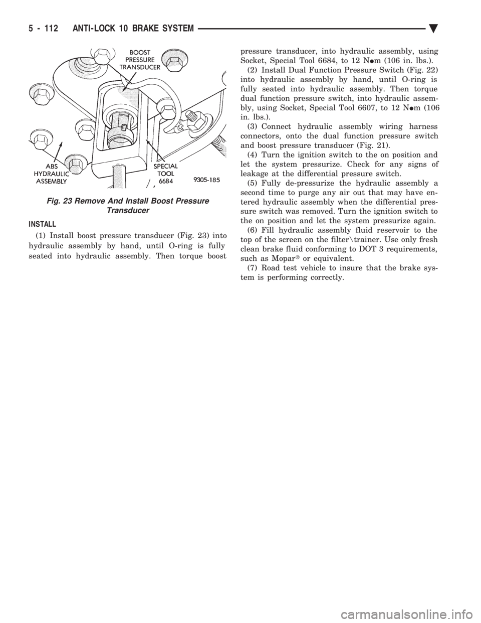
INSTALL (1) Install boost pressure transducer (Fig. 23) into
hydraulic assembly by hand, until O-ring is fully
seated into hydraulic assembly. Then torque boost pressure transducer, into hydraulic assembly, using
Socket, Special Tool 6684, to 12 N Im (106 in. lbs.).
(2) Install Dual Function Pressure Switch (Fig. 22)
into hydraulic assembly by hand, until O-ring is
fully seated into hydraulic assembly. Then torque
dual function pressure switch, into hydraulic assem-
bly, using Socket, Special Tool 6607, to 12 N Im (106
in. lbs.). (3) Connect hydraulic assembly wiring harness
connectors, onto the dual function pressure switch
and boost pressure transducer (Fig. 21). (4) Turn the ignition switch to the on position and
let the system pressurize. Check for any signs of
leakage at the differential pressure switch. (5) Fully de-pressurize the hydraulic assembly a
second time to purge any air out that may have en-
tered hydraulic assembly when the differential pres-
sure switch was removed. Turn the ignition switch to
the on position and let the system pressurize again. (6) Fill hydraulic assembly fluid reservoir to the
top of the screen on the filter rainer. Use only fresh
clean brake fluid conforming to DOT 3 requirements,
such as Mopar tor equivalent.
(7) Road test vehicle to insure that the brake sys-
tem is performing correctly.
Fig. 23 Remove And Install Boost Pressure Transducer
5 - 112 ANTI-LOCK 10 BRAKE SYSTEM Ä
Page 266 of 2438
If the vehicle is not set in motion within 3 minutes
from the time the ignition switch is set in the on po-
sition. The solenoid test is bypassed but the pump/
motor is activated briefly to verify that it is
operating correctly.
WARNING SYSTEMS OPERATION
The ABS system uses an Amber Anti-Lock Warn-
ing Lamp, located in the instrument cluster. The
purpose of the warning lamp is discussed in detail
below. The Amber Anti-Lock Warning Light will turn on
when the (CAB) detects a condition which results in
a shutdown of the Anti-Lock function. The Amber
Anti-Lock Warning Lamp is normally on until the
(CAB) completes its self tests and turns the lamp off
(approximately 1-2 seconds). When the Amber Anti-
Lock Warning Light is on only the Anti-Lock func-
tion of the brake system if affected. The standard
brake system and the ability to stop the car will not
be affected when only the Amber Anti-Lock Warning
Light is on.
NORMAL OPERATION OF WARNING LAMP
With the ignition in the Crank position, the Red
Brake Warning Lamp will turn on as a bulb check.
The Amber Anti-Lock Warning Lamp will stay on for
1-2 seconds then turn off. Once verification of the self
diagnosis is completed.
ANTI-LOCK BRAKE SYSTEM COMPONENTS
The following is a detailed description of the Anti-
Lock Brake System components. For information on
servicing the Four Wheel Disk Brake System, see the
standard Brake section of this Service Manual.
MODULATOR ASSEMBLY
WARNING: THE ONLY PART OF THE MODULATOR
ASSEMBLY THAT IS A SERVICEABLE COMPONENT
IS THE DELTA P SWITCH. THE REMAINING COM-
PONENTS OF THE MODULATOR ASSEMBLY ARE
NOT SERVICEABLE ITEMS. NO ATTEMPT SHOULD
BE MADE TO REMOVE OR SERVICE ANY OTHER
PARTS OF THE MODULATOR ASSEMBLY.
The Modulator Assembly (Fig. 1) is located under
the battery tray and is covered with an acid shield.
The Modulator Assembly contains the following com-
ponents for controlling the Anti-Lock braking sys-
tem. 2 Isolation Valves, 4 Build/Decay Valves, 4
Shuttle Orifices, 2 Fluid Sumps, 2 Accumulators, a
Pump/Motor and a Pressure Differential Valve/
Switch. Also attached to the Modulator Assembly are
4 brake tubes which are connected to an 8 way con-
nector block. The connector block is mounted to the
left frame rail below the master cylinder in the same location as the non ABS equipped combination valve.
The wheel brake lines are attached to the system via
the connector block.
ISOLATION VALVES
The Isolation Valves are used to isolate the master
cylinder from the rest of the brake hydraulic circuit
during an Anti-Lock stop. Two Isolation Valves are
used, one for the primary circuit and one for the sec-
ondary circuit. The Isolation Valves are spring
loaded in the released position. In the released posi-
tion the Isolation Valves provide a fluid path from
the master cylinder outputs to the wheel brakes via
the Build/Decay valves. When actuated it provides a
fluid path from the accumulator (which was charged
by the Pump/Motor during ABS operation) to the
Build/Decay valves through the Shuttle Orifices.
BUILD/DECAY VALVES
There are 4 Build/Decay valves, one for each
wheel. In the released position they provide a fluid
path from the wheel brakes to the Isolation Valve
through the shuttle orifices. In the actuated (decay)
position, they provide a fluid path from the wheel
brakes to the sump. The Build/Decay valves are
spring loaded in the released (build) position.
SHUTTLE ORIFICE
There are 4 Shuttle Orifice Valves, one for each
wheel. The Shuttle Orifice Valve is a hydraulically
actuated valve which shuttles when the Build/Decay
valve is actuated. Actuating of the Build/Decay valve
causes a pressure differential to be created across the
Shuttle Orifice Valve. This acts like placing an ori-
fice (restriction) in the line between the Isolation
Valve and the Build/Decay Valve. This restriction
provides a controlled build rate to each wheel brake
during an Anti-Lock stop. The Shuttle Orifice Valve
will remain in the orificed position until the ABS cy-
cle is complete. When the ABS cycle has been com-
pleted the Isolation and Build/Decay valves will
return to their released position which will equalize
the pressure across the Shuttle Orifice Valves. When
the pressure equalizes, the spring loaded Shuttle Or-
ifice valves will return to the unrestricted position.
FLUID SUMPS
There are two Fluid Sumps in the Hydraulic As-
sembly, one each for the primary and secondary hy-
draulic circuits. The Fluid Sumps store the brake
fluid that is decayed from the wheel brakes during
ABS cycle. This fluid is then pumped to an accumu-
lator and/or the hydraulic system in order to provide
build pressure. The typical pressure in the sumps is
50 psi, During ABS operation only.
5 - 116 ANTI-LOCK 6 BRAKE SYSTEM Ä
Page 267 of 2438
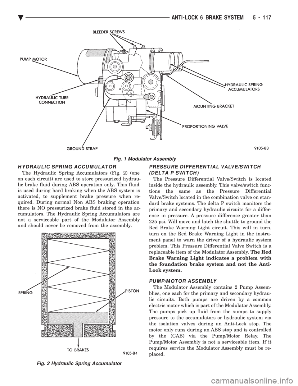
HYDRAULIC SPRING ACCUMULATOR
The Hydraulic Spring Accumulators (Fig. 2) (one
on each circuit) are used to store pressurized hydrau-
lic brake fluid during ABS operation only. This fluid
is used during hard braking when the ABS system is
activated, to supplement brake pressure when re-
quired. During normal Non ABS braking operation
there is NO pressurized brake fluid stored in the ac-
cumulators. The Hydraulic Spring Accumulators are
not a serviceable part of the Modulator Assembly
and should never be removed from the assembly.
PRESSURE DIFFERENTIAL VALVE/SWITCH
(DELTA P SWITCH)
The Pressure Differential Valve/Switch is located
inside the hydraulic assembly. This valve/switch func-
tions the same as the Pressure Differential
Valve/Switch located in the combination valve on stan-
dard brake systems. The delta P switch monitors the
primary and secondary hydraulic circuits for a differ-
ence in pressure. A pressure difference greater than
225 psi. Will move and latch the shuttle to ground the
Red Brake Warning Light circuit. This will in turn,
turn on the Red Brake Warning Light in the instru-
ment panel to warn the driver of a hydraulic system
problem. This Pressure Differential Valve Switch is a
replaceable item of the Modulator Assembly. The Red
Brake Warning Light indicates a problem with
the foundation brake system and not the Anti-
Lock system.
PUMP/MOTOR ASSEMBLY
The Modulator Assembly contains 2 Pump Assem-
blies, one each for the primary and secondary hydrau-
lic circuits. Both pumps are driven by a common
electric motor which is part of the Modulator Assembly.
The pumps pick up fluid from the sumps to supply
pressure to the accumulators or hydraulic system via
the isolation valves during an Anti-Lock stop. The
motor only runs during an ABS stop and is controlled
by the (CAB) via the Pump/Motor Relay. The
Pump/Motor Assembly is not a serviceable item. If it
requires service the Modulator Assembly must be re-
placed.
Fig. 1 Modulator Assembly
Fig. 2 Hydraulic Spring Accumulator
Ä ANTI-LOCK 6 BRAKE SYSTEM 5 - 117
Page 287 of 2438
BRAKES
CONTENTS
page page
BENDIX ANTILOCK 4 BRAKE SYSTEM ...... 12
GENERAL INFORMATION .................. 1 HYDRAULIC SYSTEM CONTROL VALVES . . . 10
SERVICE ADJUSTMENTS
.................. 3
GENERAL INFORMATION
Throughout this group, references may be made to
a particular vehicle by letter or number designation.
A chart showing the break down of these designa-
tions is included in the Introduction Section at the
front of this service manual. Standard brake equipment consists of:
² Double pin floating caliper disc front brakes.
² Rear automatic adjusting drum brakes.
² Differential valve with a brake warning switch.
² Master cylinder.
² Vacuum power booster.
² Double pin floating caliper rear disc brakes are
available on some models. The Bendix Antilock 4 Brake System, uses the fol-
lowing standard brake system components. Master
cylinder, power booster, caliper assemblies, braking
discs, pedal assembly, brake lines and hoses. The
unique parts of the Bendix Antilock 4 Brake System
consists of the following components, modulator as-
sembly, unique proportioning valves, unique junction
block, wheel speed sensors, tone wheels, and elec-
tronic control unit. These components will be de-
scribed in detail in the Bendix Antilock 4 Brake
System section in this service manual supplement. The hydraulic system, (Fig. 1) on the Bendix Anti-
lock 4 brake system is diagonally split. Diagonally
split hydraulic brake systems, have the left front and
right rear brakes on one hydraulic system and the
right front and left rear on the other. A diagonally
split hydraulic brake system, will maintain half of
the vehicles braking capability if there is a failure in
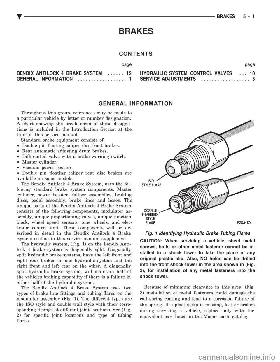
either half of the hydraulic system. The Bendix Antilock 4 Brake System uses two
types of brake line fittings and tubing flares on the
modulator assembly (Fig. 1). The different types are
the ISO style and double wall style with their corre-
sponding fittings at different joint locations. See (Fig.
2) for specific joint locations and type of tubing
flares. CAUTION: When servicing a vehicle, sheet metal
screws, bolts or other metal fastener cannot be in-
stalled in a shock tower to take the place of any
original plastic clip. Also, NO holes can be drilled
into the front shock tower in the area shown in (Fig.
3), for installation of any metal fasteners into the
shock tower.
Because of minimum clearance in this area, (Fig.
3) installation of metal fasteners could damage the
coil spring coating and lead to a corrosion failure of
the spring. If a plastic clip is missing, lost or broken
during servicing a vehicle, replace only with the
equivalent part listed in the Mopar parts catalog.
Fig. 1 Identifying Hydraulic Brake Tubing Flares
Ä BRAKES 5 - 1
Page 296 of 2438
HYDRAULIC SYSTEM CONTROL VALVES INDEX
page page
General Information ....................... 10
Hydraulic System Service Procedures ......... 11 Pressure Differential Warning Light Switch
...... 10
GENERAL INFORMATION
All models equipped with a Bendix Antilock 4 Brake
System have 2 screw-in type proportioning valves.
There is 1 valve for each individual rear wheel hydrau-
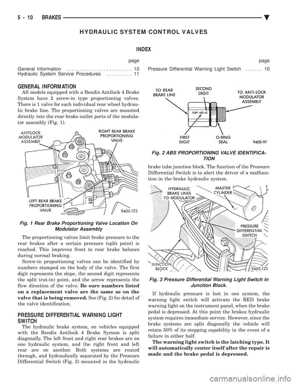
lic brake line. The proportioning valves are mounted
directly into the rear brake outlet ports of the modula-
tor assembly (Fig. 1).
The proportioning valves limit brake pressure to the
rear brakes after a certain pressure (split point) is
reached. This improves front to rear brake balance
during normal braking. Screw-in proportioning valves can be identified by
numbers stamped on the body of the valve. The first
digit represents the slope, the second digit represents
the split (cut-in) point, and the arrow represents the
flow direction of the valve. Be sure numbers listed
on a replacement valve are the same as on the
valve that is being removed. See (Fig. 2) for detail of
the valve identification.
PRESSURE DIFFERENTIAL WARNING LIGHT
SWITCH
The hydraulic brake system, on vehicles equipped
with the Bendix Antilock 4 Brake System is split
diagonally. The left front and right rear brakes are on
one hydraulic system, and the right front and left
rear are on another. Both systems are routed
through, and hydraulically separated by the Pressure
Differential Switch (Fig. 3) mounted in the hydraulic brake tube junction block. The function of the Pressure
Differential Switch is to alert the driver of a malfunc-
tion in the brake hydraulic system.
If hydraulic pressure is lost in one system, the
warning light switch will activate the RED brake
warning light on the instrument panel, when the brake
pedal is depressed. At this point the brakes hydraulic
system requires immediate service. However, since the
brake systems are split diagonally the vehicle will
retain 50% of its stopping capability in the event of a
failure in either half. The warning light switch is the latching type. It
will automatically center itself after the repair is
made and the brake pedal is depressed.
Fig. 1 Rear Brake Proportioning Valve Location On Modulator Assembly
Fig. 2 ABS PROPORTIONING VALVE IDENTIFICA- TION
Fig. 3 Pressure Differential Warning Light Switch InJunction Block.
5 - 10 BRAKES Ä
Page 302 of 2438
(2) The voltage output from each of the wheel
speed sensors is verified to be within the correct op-
erating range. If a vehicle is not set in motion within 3 minutes
from the time the ignition switch is turned to the on
position. The solenoid valve test is bypassed but the
pump/motor is activated briefly to verify that it is op-
erating correctly.
WARNING SYSTEMS OPERATION
The ABS system uses an Amber Antilock Warning
Lamp, located in the instrument cluster. The purpose
of the warning lamp is discussed in detail below. The Amber Antilock Warning Light will turn on
whenever the CAB detects a condition which results
in a shutdown of the Antilock brake system. The
Amber Antilock Warning Lamp is normally on until
the CAB completes its self tests and turns the lamp
off (approximately 1-2 seconds). When the Amber
Antilock Warning Light is on, only the Antilock
brake function of the brake system if affected. The
standard brake system and the ability to stop the car
will not be affected when only the Amber Antilock
Warning Light is on.
NORMAL OPERATION OF WARNING LAMP
With ignition key turned to the Crank position, the
Red Brake Warning Lamp and Amber Antilock
Warning Lamp will turn on as a bulb check. The
Amber Antilock Warning Lamp will stay on for 1-2
seconds then turn off, once verification of Antilock
Brake System self diagnosis is completed.
ANTILOCK BRAKE SYSTEM COMPONENTS
The following is a detailed description of the Ben-
dix Antilock 4 Brake System components. For infor-
mation on servicing the Four Wheel Disc Brake
System, see the standard Brake section in the Front
Wheel Drive Car, chassis service manual.
MODULATOR ASSEMBLY
WARNING: THE ONLY COMPONENTS OF THE
MODULATOR ASSSEMBLY THAT ARE SERVICE-
ABLE, ARE THE 2 PROPORTIONING VALVES,
BLEED SCREWS AND THREAD SAVERS. THE RE-
MAINING COMPONENTS OF THE MODULATOR AS-
SEMBLY ARE NOT INTENDED TO BE
SERVICEABLE ITEMS. NO ATTEMPT SHOULD BE
MADE TO REMOVE OR SERVICE ANY OTHER COM-
PONENTS OF THE MODEULATOR ASSEMBLY.
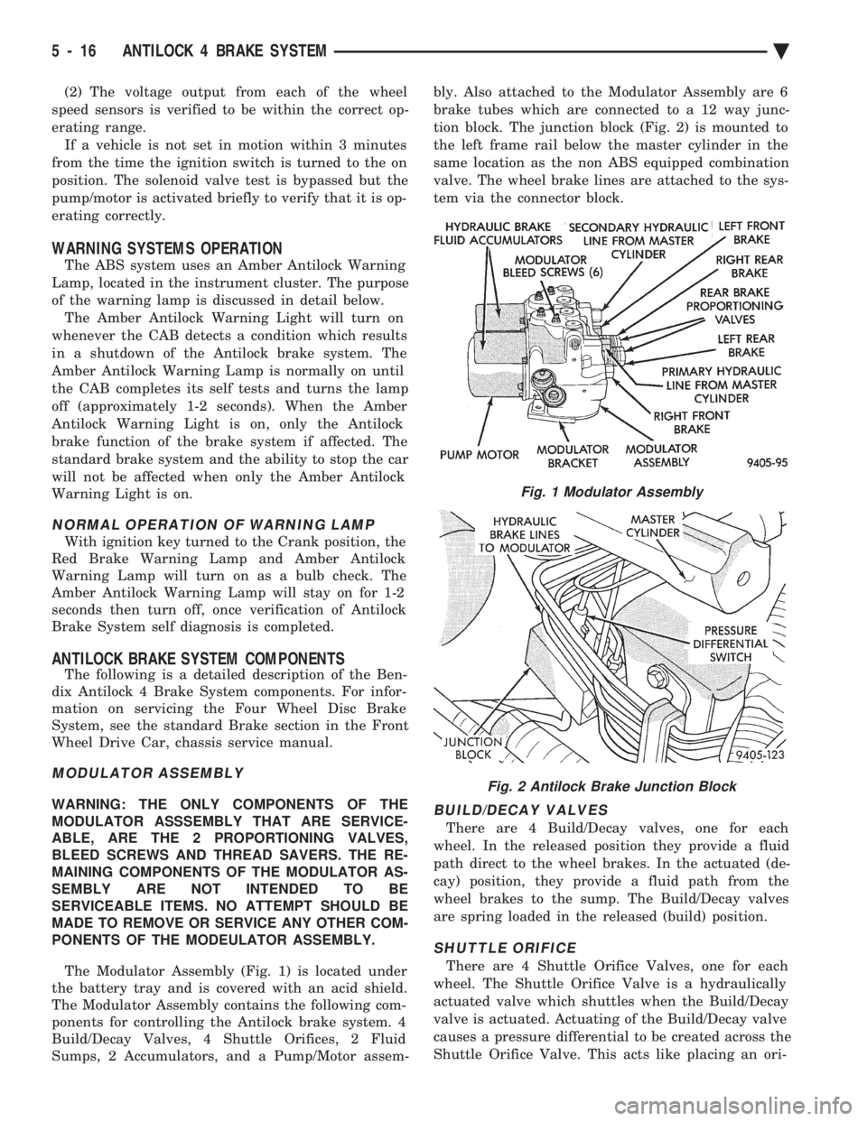
The Modulator Assembly (Fig. 1) is located under
the battery tray and is covered with an acid shield.
The Modulator Assembly contains the following com-
ponents for controlling the Antilock brake system. 4
Build/Decay Valves, 4 Shuttle Orifices, 2 Fluid
Sumps, 2 Accumulators, and a Pump/Motor assem- bly. Also attached to the Modulator Assembly are 6
brake tubes which are connected to a 12 way junc-
tion block. The junction block (Fig. 2) is mounted to
the left frame rail below the master cylinder in the
same location as the non ABS equipped combination
valve. The wheel brake lines are attached to the sys-
tem via the connector block.BUILD/DECAY VALVES
There are 4 Build/Decay valves, one for each
wheel. In the released position they provide a fluid
path direct to the wheel brakes. In the actuated (de-
cay) position, they provide a fluid path from the
wheel brakes to the sump. The Build/Decay valves
are spring loaded in the released (build) position.
SHUTTLE ORIFICE
There are 4 Shuttle Orifice Valves, one for each
wheel. The Shuttle Orifice Valve is a hydraulically
actuated valve which shuttles when the Build/Decay
valve is actuated. Actuating of the Build/Decay valve
causes a pressure differential to be created across the
Shuttle Orifice Valve. This acts like placing an ori-
Fig. 1 Modulator Assembly
Fig. 2 Antilock Brake Junction Block
5 - 16 ANTILOCK 4 BRAKE SYSTEM Ä
Page 303 of 2438
fice (restriction) in the line between the wheel and
the Build/Decay Valve. This restriction provides a
controlled build rate to each wheel brake during an
Antilock stop. The Shuttle Orifice Valve will remain
in the orificed position until the ABS cycle is com-
plete. When the ABS cycle has been completed the
Build/Decay valves will return to their released posi-
tion which will equalize the pressure across the
Shuttle Orifice Valves. When the pressure equalizes,
the spring loaded Shuttle Orifice valves will return
to the unrestricted position.
FLUID SUMPS
There are two Fluid Sumps in the Hydraulic As-
sembly, one for the primary and secondary hydraulic
circuits. The Fluid Sumps store the brake fluid that
is decayed from the wheel brakes during an ABS cy-
cle. This fluid is then pumped to an accumulator
and/or the hydraulic system in order to provide build
pressure. The typical pressure in the sumps is 50 psi,
during ABS operation only.
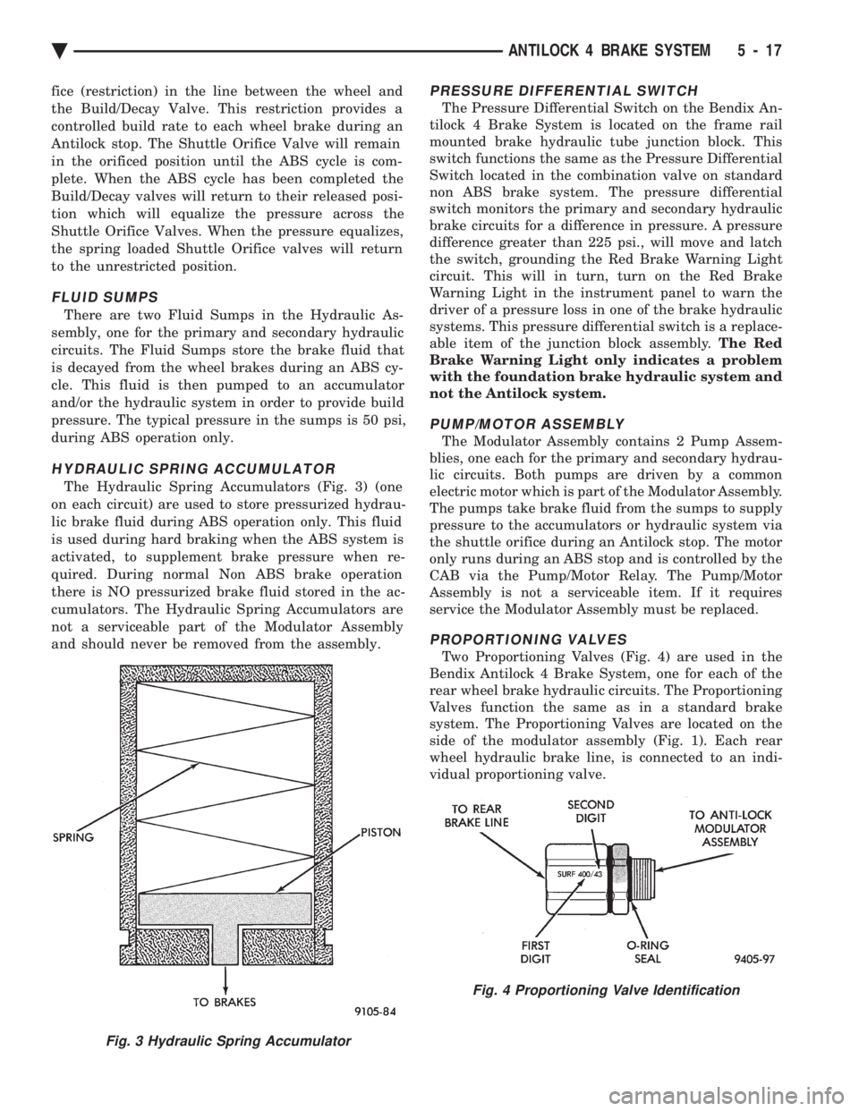
HYDRAULIC SPRING ACCUMULATOR
The Hydraulic Spring Accumulators (Fig. 3) (one
on each circuit) are used to store pressurized hydrau-
lic brake fluid during ABS operation only. This fluid
is used during hard braking when the ABS system is
activated, to supplement brake pressure when re-
quired. During normal Non ABS brake operation
there is NO pressurized brake fluid stored in the ac-
cumulators. The Hydraulic Spring Accumulators are
not a serviceable part of the Modulator Assembly
and should never be removed from the assembly.
PRESSURE DIFFERENTIAL SWITCH
The Pressure Differential Switch on the Bendix An-
tilock 4 Brake System is located on the frame rail
mounted brake hydraulic tube junction block. This
switch functions the same as the Pressure Differential
Switch located in the combination valve on standard
non ABS brake system. The pressure differential
switch monitors the primary and secondary hydraulic
brake circuits for a difference in pressure. A pressure
difference greater than 225 psi., will move and latch
the switch, grounding the Red Brake Warning Light
circuit. This will in turn, turn on the Red Brake
Warning Light in the instrument panel to warn the
driver of a pressure loss in one of the brake hydraulic
systems. This pressure differential switch is a replace-
able item of the junction block assembly. The Red
Brake Warning Light only indicates a problem
with the foundation brake hydraulic system and
not the Antilock system.
PUMP/MOTOR ASSEMBLY
The Modulator Assembly contains 2 Pump Assem-
blies, one each for the primary and secondary hydrau-
lic circuits. Both pumps are driven by a common
electric motor which is part of the Modulator Assembly.
The pumps take brake fluid from the sumps to supply
pressure to the accumulators or hydraulic system via
the shuttle orifice during an Antilock stop. The motor
only runs during an ABS stop and is controlled by the
CAB via the Pump/Motor Relay. The Pump/Motor
Assembly is not a serviceable item. If it requires
service the Modulator Assembly must be replaced.
PROPORTIONING VALVES
Two Proportioning Valves (Fig. 4) are used in the
Bendix Antilock 4 Brake System, one for each of the
rear wheel brake hydraulic circuits. The Proportioning
Valves function the same as in a standard brake
system. The Proportioning Valves are located on the
side of the modulator assembly (Fig. 1). Each rear
wheel hydraulic brake line, is connected to an indi-
vidual proportioning valve.
Fig. 3 Hydraulic Spring Accumulator
Fig. 4 Proportioning Valve Identification
Ä ANTILOCK 4 BRAKE SYSTEM 5 - 17
Page 321 of 2438
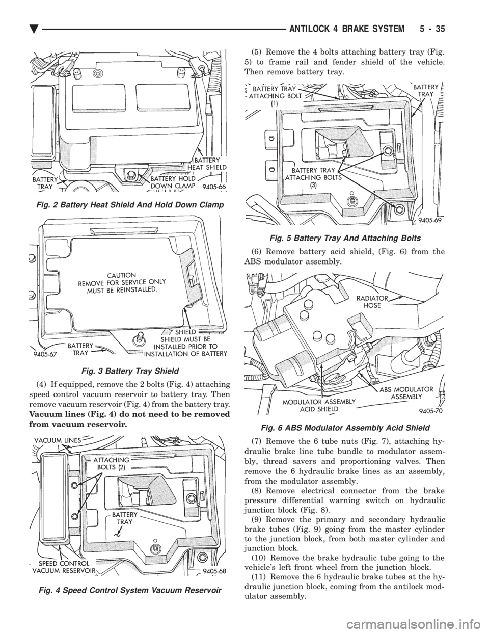
(4) If equipped, remove the 2 bolts (Fig. 4) attaching
speed control vacuum reservoir to battery tray. Then
remove vacuum reservoir (Fig. 4) from the battery tray.
Vacuum lines (Fig. 4) do not need to be removed
from vacuum reservoir. (5) Remove the 4 bolts attaching battery tray (Fig.
5) to frame rail and fender shield of the vehicle.
Then remove battery tray.
(6) Remove battery acid shield, (Fig. 6) from the
ABS modulator assembly.
(7) Remove the 6 tube nuts (Fig. 7), attaching hy-
draulic brake line tube bundle to modulator assem-
bly, thread savers and proportioning valves. Then
remove the 6 hydraulic brake lines as an assembly,
from the modulator assembly. (8) Remove electrical connector from the brake
pressure differential warning switch on hydraulic
junction block (Fig. 8). (9) Remove the primary and secondary hydraulic
brake tubes (Fig. 9) going from the master cylinder
to the junction block, from both master cylinder and
junction block. (10) Remove the brake hydraulic tube going to the
vehicle's left front wheel from the junction block. (11) Remove the 6 hydraulic brake tubes at the hy-
draulic junction block, coming from the antilock mod-
ulator assembly.
Fig. 5 Battery Tray And Attaching Bolts
Fig. 6 ABS Modulator Assembly Acid Shield
Fig. 2 Battery Heat Shield And Hold Down Clamp
Fig. 3 Battery Tray Shield
Fig. 4 Speed Control System Vacuum Reservoir
Ä ANTILOCK 4 BRAKE SYSTEM 5 - 35