key battery CHEVROLET DYNASTY 1993 User Guide
[x] Cancel search | Manufacturer: CHEVROLET, Model Year: 1993, Model line: DYNASTY, Model: CHEVROLET DYNASTY 1993Pages: 2438, PDF Size: 74.98 MB
Page 479 of 2438
FAILURE TO START TEST
This no-start test checks the camshaft position sen-
sor and crankshaft position sensor. The powertrain control module (PCM) supplies 8.0
volts to the camshaft position sensor and crankshaft
position sensor through one circuit. If the 8.0-volt
supply circuit shorts to ground, neither sensor will
produce a signal (output voltage to the PCM). When the ignition key is turned and left in the On
position , the PCM automatically energizes the auto shutdown (ASD) relay. However, the PCM de-energizes
the relay within one second because it has not received
a crankshaft position sensor signal indicating engine
rotation.
During cranking, the ASD relay will not energize
until the PCM receives a crankshaft signal. Secondly,
the ASD relay remains energized only if the PCM
senses a camshaft position sensor signal immediately
after detecting the crankshaft position sensor signal. (1) Check battery voltage. Voltage should approxi-
mately 12.66 volts or higher to perform failure to start
test. (2) Disconnect the harness connector from the coil
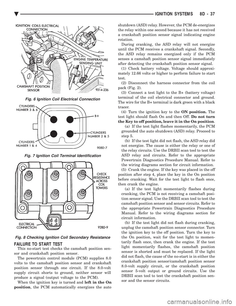
pack (Fig. 2). (3) Connect a test light to the B+ (battery voltage)
terminal of the coil electrical connector and ground.
The wire for the B+ terminal is dark green with a black
tracer. (4) Turn the ignition key to the ON position.The
test light should flash On and then Off. Do not turn
the Key to off position, leave it in the On position .
(a) If the test light flashes momentarily, the PCM
grounded the auto shutdown (ASD) relay. Proceed to
step 5. (b) If the test light did not flash, the ASD relay did
not energize. The cause is either the relay or one of
the relay circuits. Use the DRBII scan tool to test the
ASD relay and circuits. Refer to the appropriate
Powertrain Diagnostics Procedure Manual. Refer to
the wiring diagrams section for circuit information.
(5) Crank the engine. If the key was placed in the off
position after step 4, place the key in the On position
before cranking. Wait for the test light to flash once,
then crank the engine. (a) If the test light momentarily flashes during
cranking, the PCM is not receiving a camshaft posi-
tion sensor signal. Use the DRBII scan tool to test the
camshaft position sensor and sensor circuits. Refer to
the appropriate Powertrain Diagnostics Procedure
Manual. Refer to the wiring diagrams section for
circuit information. (b) If the test light did not flash during cranking,
unplug the camshaft position sensor connector. Turn
the ignition key to the off position. Turn the key to
the On position, wait for the test light to momen-
tarily flash once, then crank the engine. If the test
light momentarily flashes, the camshaft position
sensor is shorted and must be replaced. If the light
did not flash, the cause of the no-start is in either the
crankshaft position sensor/camshaft position sensor
8.0-volt supply circuit, or the crankshaft position
sensor 5-volt output or ground circuits. Use the
DRBII scan tool to test the crankshaft position sen-
sor and the sensor circuits.
Fig. 6 Ignition Coil Electrical Connection
Fig. 7 Ignition Coil Terminal Identification
Fig. 8 Checking Ignition Coil Secondary Resistance
Ä IGNITION SYSTEMS 8D - 37
Page 487 of 2438
IGNITION SWITCH
IGNITION SWITCH AND KEY CYLINDER SERVICE
The ignition switch is located on the steering col-
umn. The Key In Switch is located in the ignition
switch module. For diagnosis of the Key In Switch,
refer to Section 8M.
REMOVAL
If the vehicle has a floor mounted gear shifter,
place the selector in the Park position. (1) Disconnect negative cable from battery.
(2) If the vehicle has a tilt column, remove the tilt
lever by turning it counterclockwise. (3) Remove upper and lower covers from steering
column.
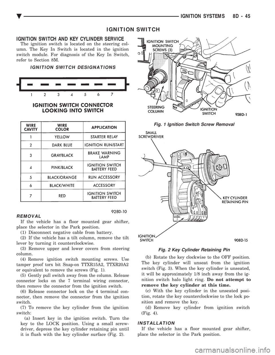
(4) Remove ignition switch mounting screws. Use
tamper proof torx bit Snap-on TTXR15A2, TTXR20A2
or equivalent to remove the screws (Fig. 1). (5) Gently pull switch away from the column. Release
connector locks on the 7 terminal wiring connector,
then remove the connector from the ignition switch.
(6) Release connector lock on the 4 terminal con-
nector, then remove the connector from the ignition
switch. (7) To remove the key cylinder from the ignition
switch: (a) Insert key in the ignition switch. Turn the
key to the LOCK position. Using a small screw-
driver, depress the key cylinder retaining pin until
it is flush with the key cylinder surface (Fig. 2). (b) Rotate the key clockwise to the OFF position.
The key cylinder will unseat from the ignition
switch (Fig. 3). When the key cylinder is unseated,
it will be approximately 1/8 inch away from the ig-
nition switch halo light ring. Do not attempt to
remove the key cylinder at this time. (c) With the key cylinder in the unseated posi-
tion, rotate the key counterclockwise to the lock po-
sition and remove the key. (d) Remove key cylinder from ignition switch
(Fig. 4).
INSTALLATION
If the vehicle has a floor mounted gear shifter,
place the selector in the Park position.
IGNITION SWITCH DESIGNATIONS
Fig. 1 Ignition Switch Screw Removal
Fig. 2 Key Cylinder Retaining Pin
Ä IGNITION SYSTEMS 8D - 45
Page 488 of 2438
(1) Connect electrical connectors to the ignition
switch. Make sure that the switch locking tabs are fully
seated in the wiring connectors. (2) Before attaching the ignition switch to a tilt
steering column, the transaxle shifter must be in the
Park position. Also the park lock dowel pin and the
column lock flag must be properly indexed before
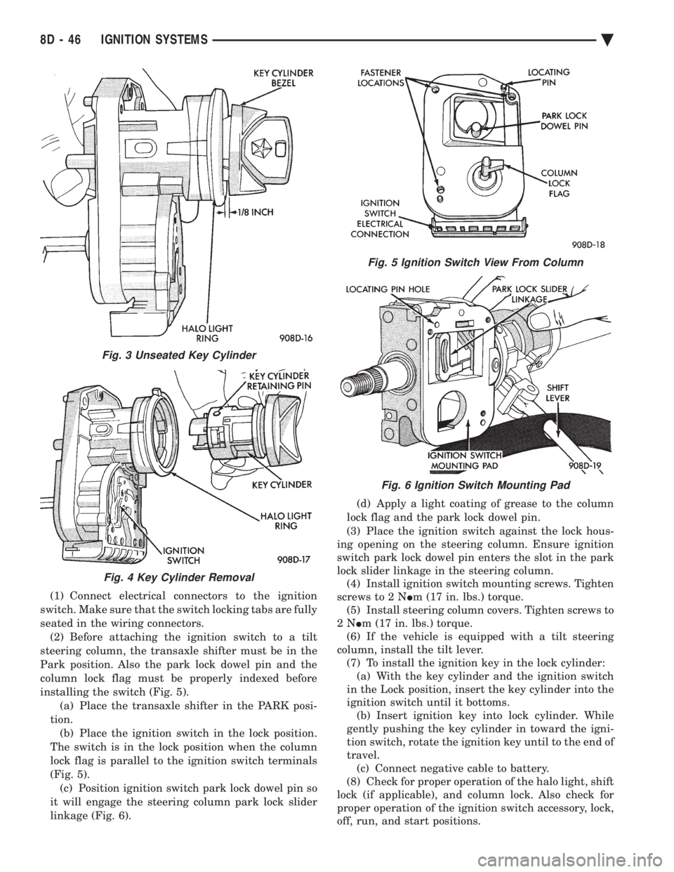
installing the switch (Fig. 5). (a) Place the transaxle shifter in the PARK posi-
tion. (b) Place the ignition switch in the lock position.
The switch is in the lock position when the column
lock flag is parallel to the ignition switch terminals
(Fig. 5). (c) Position ignition switch park lock dowel pin so
it will engage the steering column park lock slider
linkage (Fig. 6). (d) Apply a light coating of grease to the column
lock flag and the park lock dowel pin.
(3) Place the ignition switch against the lock hous-
ing opening on the steering column. Ensure ignition
switch park lock dowel pin enters the slot in the park
lock slider linkage in the steering column. (4) Install ignition switch mounting screws. Tighten
screws to 2 N Im (17 in. lbs.) torque.
(5) Install steering column covers. Tighten screws to
2N Im (17 in. lbs.) torque.
(6) If the vehicle is equipped with a tilt steering
column, install the tilt lever. (7) To install the ignition key in the lock cylinder:(a) With the key cylinder and the ignition switch
in the Lock position, insert the key cylinder into the
ignition switch until it bottoms. (b) Insert ignition key into lock cylinder. While
gently pushing the key cylinder in toward the igni-
tion switch, rotate the ignition key until to the end of
travel. (c) Connect negative cable to battery.
(8) Check for proper operation of the halo light, shift
lock (if applicable), and column lock. Also check for
proper operation of the ignition switch accessory, lock,
off, run, and start positions.
Fig. 3 Unseated Key Cylinder
Fig. 4 Key Cylinder Removal
Fig. 5 Ignition Switch View From Column
Fig. 6 Ignition Switch Mounting Pad
8D - 46 IGNITION SYSTEMS Ä
Page 501 of 2438
(3) When testing temperature, allow the engine to
run until the vehicle reaches a normal operating
temperature. Turn ignition OFF, and remove gauge
from cluster. (a) Testing oil pressure gauge, engine needs to
be running. (b) Measure and record the resistance between
sending unit pin and ground pin of the gauge in
question. Refer to Gauge Calibration. (c) It is important to have the same engine tem-
perature and engine speed when checking temper-
ature and oil pressure gauges position. The time
between gauge position reading and sending unit
measuring should be kept to a minimum. (d) If resistance and gauge position are not sim-
ilar, replace gauge. (e) If OK, test resistance from the sending unit
to the cluster connector. (f) If resistance reading is different, check
printed circuit board for contact to cluster connec-
tor. (g) If OK and contacts are not distorted, replace
printed circuit board. (h) If everything checks out OK, refer to sending
unit test.
(4) If fuel gauge does not meet specifications, refer
to Group 14, Fuel for the test procedure.
GAUGE CALIBRATION
(1) Remove the gauge.
(2) Check for ignition voltage and ground to the
gauge. (3) With the ignition key in the OFF position, re-
place gauge. Turn the ignition key to the ON posi-
tion. To test oil pressure gauge engine must be
running. When testing oil or temperature gauge the
engine should be at normal operating temperature.
Record the gauge position. (4) Remove gauge and record the resistance be-
tween the sending unit pin and the gauge ground
pin. When checking gauges, it is important to have
the same engine temperature and speed when noting
gauge position. The time between gauge reading and
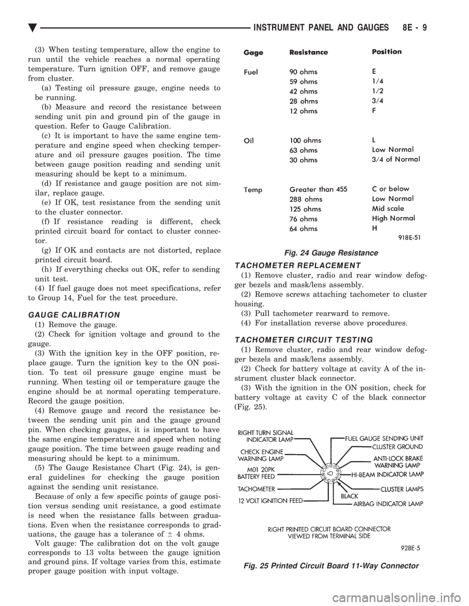
measuring should be kept to a minimum. (5) The Gauge Resistance Chart (Fig. 24), is gen-
eral guidelines for checking the gauge position
against the sending unit resistance. Because of only a few specific points of gauge posi-
tion versus sending unit resistance, a good estimate
is need when the resistance falls between gradua-
tions. Even when the resistance corresponds to grad-
uations, the gauge has a tolerance of 64 ohms.
Volt gauge: The calibration dot on the volt gauge
corresponds to 13 volts between the gauge ignition
and ground pins. If voltage varies from this, estimate
proper gauge position with input voltage.
TACHOMETER REPLACEMENT
(1) Remove cluster, radio and rear window defog-
ger bezels and mask/lens assembly. (2) Remove screws attaching tachometer to cluster
housing. (3) Pull tachometer rearward to remove.
(4) For installation reverse above procedures.
TACHOMETER CIRCUIT TESTING
(1) Remove cluster, radio and rear window defog-
ger bezels and mask/lens assembly. (2) Check for battery voltage at cavity A of the in-
strument cluster black connector. (3) With the ignition in the ON position, check for
battery voltage at cavity C of the black connector
(Fig. 25).
Fig. 24 Gauge Resistance
Fig. 25 Printed Circuit Board 11-Way Connector
Ä INSTRUMENT PANEL AND GAUGES 8E - 9
Page 516 of 2438
MESSAGE CENTER
The message center is a car graphic warning lamp
module. This conventional warning system and lo-
cated above the headlamp switch.
ELECTRONIC DIGITAL CLOCK
The electronic digital clock is in the radio. The
clock and radio each use the display panel built into
the radio. A digital readout indicates the time in
hours and minutes whenever the ignition switch is in
the ON or ACC position. When the ignition switch is in the OFF position, or
when the radio frequency is being displayed, time
keeping is accurately maintained. The procedure for setting the clock varies slightly
with each radio. The correct procedure is described
under the individual radio operating instructions re-
ferred to in the Owner's Manual supplied with the
vehicle.
AIR BAG WARNING SYSTEM
For testing of this system refer to Group 8M, Re-
straint Systems.
MECHANICAL CLUSTER AND GAUGE SERVICE
CAUTION: Disconnect negative battery cable, in en-
gine compartment, before servicing instrument
panel. When power is required for test purposes,
reconnect battery cable for the test only.
Disconnect negative battery cable after test and be-
fore continuing service procedures.
SENDING UNIT TEST
When a problem occurs with a cluster gauge, be-
fore disassembling the cluster to check the gauge,
check for a defective sending unit or wiring. (1) Sending units and wiring can be checked by
grounding the connector leads, at the sending unit,
in the vehicle. (2) With the ignition in the ON position; a
grounded input will cause the oil, fuel or tempera-
ture gauge to read at or above maximum.
CHECK GAUGES WARNING LAMP TESTS
The check gauges warning lamp is illuminated by
the low oil pressure sending unit switch or the body
controller when there is high temperature or charg-
ing system failure. To test the lamp, turn ignition key to the ON po-
sition without starting the vehicle. The low oil pres-
sure switch is grounded and the light will be on
indefinitely. If the lamp fails to light, pull the cluster and check
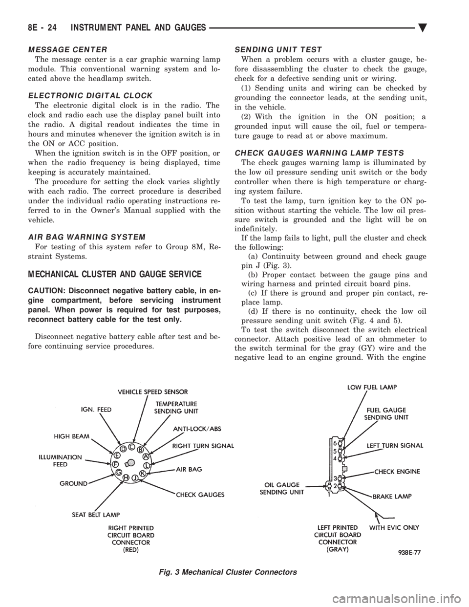
the following: (a) Continuity between ground and check gauge
pin J (Fig. 3). (b) Proper contact between the gauge pins and
wiring harness and printed circuit board pins. (c) If there is ground and proper pin contact, re-
place lamp. (d) If there is no continuity, check the low oil
pressure sending unit switch (Fig. 4 and 5).
To test the switch disconnect the switch electrical
connector. Attach positive lead of an ohmmeter to
the switch terminal for the gray (GY) wire and the
negative lead to an engine ground. With the engine
Fig. 3 Mechanical Cluster Connectors
8E - 24 INSTRUMENT PANEL AND GAUGES Ä
Page 520 of 2438
or bind the transmission range indicator guide tube
and position guide tube in original location.(5) Adjust with tool if necessary to center pointer
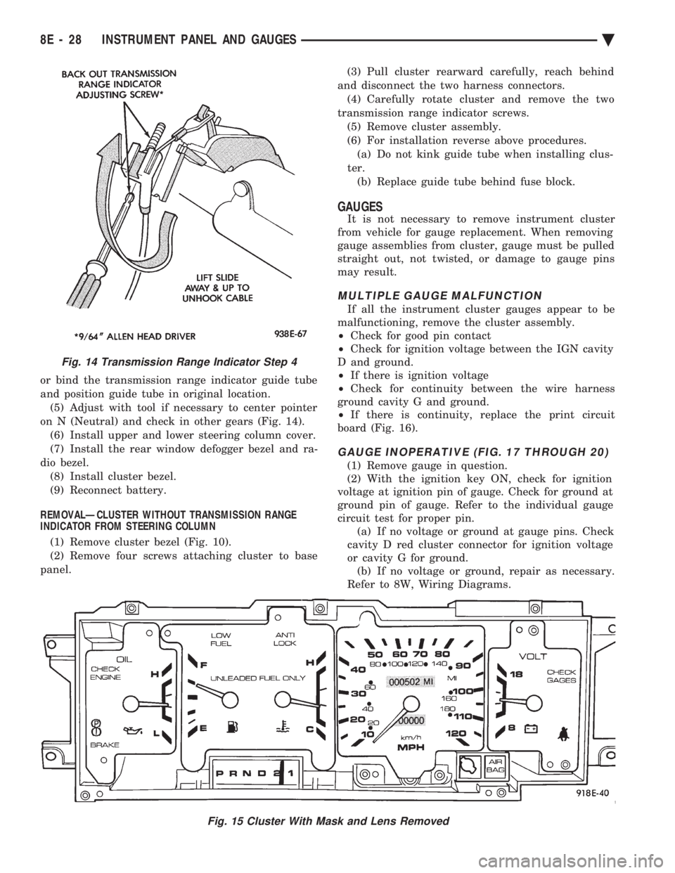
on N (Neutral) and check in other gears (Fig. 14). (6) Install upper and lower steering column cover.
(7) Install the rear window defogger bezel and ra-
dio bezel. (8) Install cluster bezel.
(9) Reconnect battery.
REMOVALÐCLUSTER WITHOUT TRANSMISSION RANGE
INDICATOR FROM STEERING COLUMN
(1) Remove cluster bezel (Fig. 10).
(2) Remove four screws attaching cluster to base
panel. (3) Pull cluster rearward carefully, reach behind
and disconnect the two harness connectors. (4) Carefully rotate cluster and remove the two
transmission range indicator screws. (5) Remove cluster assembly.
(6) For installation reverse above procedures. (a) Do not kink guide tube when installing clus-
ter. (b) Replace guide tube behind fuse block.
GAUGES
It is not necessary to remove instrument cluster
from vehicle for gauge replacement. When removing
gauge assemblies from cluster, gauge must be pulled
straight out, not twisted, or damage to gauge pins
may result.
MULTIPLE GAUGE MALFUNCTION
If all the instrument cluster gauges appear to be
malfunctioning, remove the cluster assembly.
² Check for good pin contact
² Check for ignition voltage between the IGN cavity
D and ground.
² If there is ignition voltage
² Check for continuity between the wire harness
ground cavity G and ground.
² If there is continuity, replace the print circuit
board (Fig. 16).
GAUGE INOPERATIVE (FIG. 17 THROUGH 20)
(1) Remove gauge in question.
(2) With the ignition key ON, check for ignition
voltage at ignition pin of gauge. Check for ground at
ground pin of gauge. Refer to the individual gauge
circuit test for proper pin. (a) If no voltage or ground at gauge pins. Check
cavity D red cluster connector for ignition voltage
or cavity G for ground. (b) If no voltage or ground, repair as necessary.
Refer to 8W, Wiring Diagrams.
Fig. 15 Cluster With Mask and Lens Removed
Fig. 14 Transmission Range Indicator Step 4
8E - 28 INSTRUMENT PANEL AND GAUGES Ä
Page 536 of 2438
(4) Remove six screws holding the cluster mask
and lens assembly. (5) Pull cluster mask and lens rearward to remove
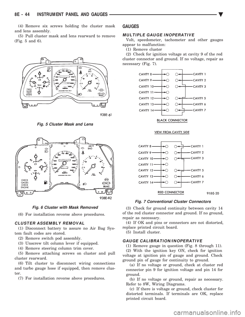
(Fig. 5 and 6).
(6) For installation reverse above procedures.
CLUSTER ASSEMBLY REMOVAL
(1) Disconnect battery to assure no Air Bag Sys-
tem fault codes are stored. (2) Remove switch pod assembly.
(3) Unscrew tilt column lever if equipped.
(4) Remove steering column trim cover.
(5) Remove attaching screws on cluster and pull
cluster rearward. (6) Tilt cluster to disconnect wiring connections
and turbo gauge hose if equipped, then remove clus-
ter. (7) For installation reverse above procedures.
GAUGES
MULTIPLE GAUGE INOPERATIVE
Volt, speedometer, tachometer and other gauges
appear to malfunction: (1) Remove cluster
(2) Check for ignition voltage at cavity 9 of the red
cluster connector and ground. If no voltage, repair as
necessary (Fig. 7).
(3) Check for ground continuity between cavity 14
of the red cluster connector and ground. If no ground,
repair as necessary. (4) If OK and pins or connectors are not distorted,
replace printed circuit board. (5) Install cluster.
GAUGE CALIBRATION/INOPERATIVE
(1) Remove gauge in question (Fig. 8 through 11).
(2) With the ignition key ON, check for ignition
voltage at ignition pin of gauge and ground. Check
ground pin of gauge for continuity to ground. (a) If no voltage or ground, check at cluster red
connector pin 9 for ignition voltage and pin 14 for
ground. (b) If no voltage or ground, repair as necessary.
Refer to 8W, Wiring Diagrams. (c) If there is voltage or ground, check cluster for
distorted terminals. If terminals are OK, replace
printed circuit board.
Fig. 5 Cluster Mask and Lens
Fig. 6 Cluster with Mask Removed
Fig. 7 Conventional Cluster Connectors
8E - 44 INSTRUMENT PANEL AND GAUGES Ä
Page 553 of 2438
(5) Reconnect battery.
GAUGES
CAUTION: During the removal and installation
watch overlays are not damage.
It is not necessary to remove instrument cluster
from vehicle for gauge replacement. When removing gauge assemblies from cluster,
gauge must be pulled straight out, not twisted, or
damage to gauge pins may result.
MULTIPLE GAUGE INOPERATIVE
Volt, speedometer, tachometer and other gauges
appear to malfunction. Also check warning indicator
lamps: (1) Remove cluster
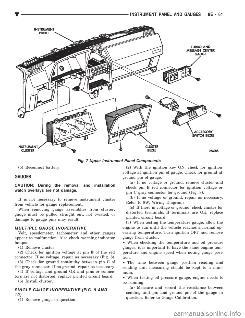
(2) Check for ignition voltage at pin E of the red
connector. If no voltage, repair as necessary (Fig. 8). (3) Check for ground continuity between pin C of
the gray connector. If no ground, repair as necessary. (4) If voltage and ground OK and pins or connec-
tors are not distorted, replace printed circuit board. (5) Install cluster.
SINGLE GAUGE INOPERATIVE (FIG. 9 AND10)
(1) Remove gauge in question. (2) With the ignition key ON, check for ignition
voltage at ignition pin of gauge. Check for ground at
ground pin of gauge. (a) If no voltage or ground, remove cluster and
check pin E red connector for ignition voltage or
pin C gray connector for ground (Fig. 8). (b) If no voltage or ground, repair as necessary.
Refer to 8W, Wiring Diagrams. (c) If there is voltage or ground, check cluster for
distorted terminals. If terminals are OK, replace
printed circuit board.
(3) When testing the temperature gauge, allow the
engine to run until the vehicle reaches a normal op-
erating temperature. Turn ignition OFF and remove
gauge from cluster.
² When checking the temperature and oil pressure
gauges, it is important to have the same engine tem-
perature and engine speed when noting gauge posi-
tion.
² The time between gauge position reading and
sending unit measuring should be kept to a mini-
mum.
² When testing oil pressure gauge, engine needs to
be running. (a) Measure and record the resistance between
sending unit pin and ground pin of the gauge in
question. Refer to Gauge Calibration.
Fig. 7 Upper Instrument Panel Components
Ä INSTRUMENT PANEL AND GAUGES 8E - 61
Page 555 of 2438
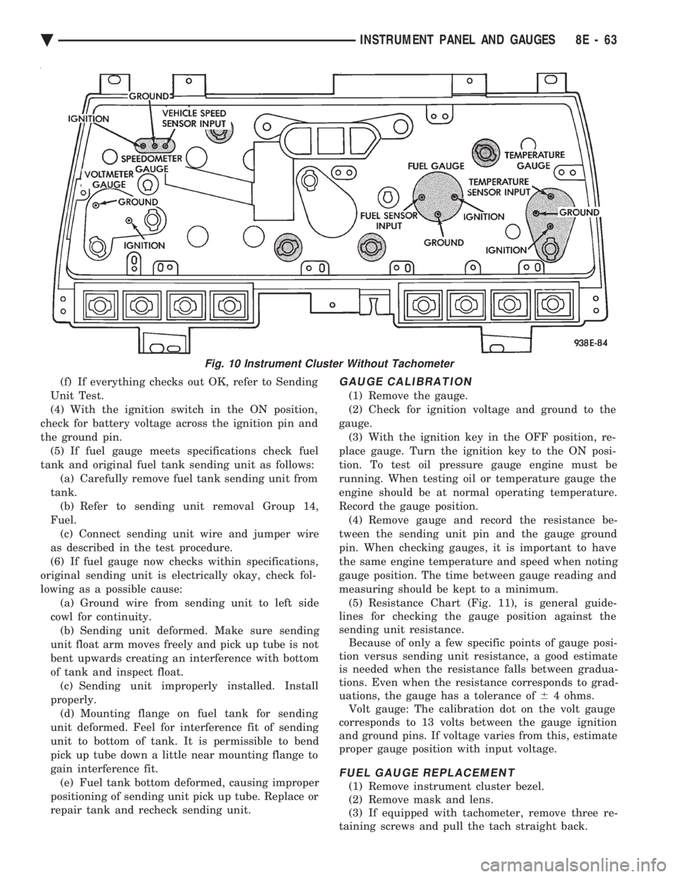
(f) If everything checks out OK, refer to Sending
Unit Test.
(4) With the ignition switch in the ON position,
check for battery voltage across the ignition pin and
the ground pin. (5) If fuel gauge meets specifications check fuel
tank and original fuel tank sending unit as follows: (a) Carefully remove fuel tank sending unit from
tank. (b) Refer to sending unit removal Group 14,
Fuel. (c) Connect sending unit wire and jumper wire
as described in the test procedure.
(6) If fuel gauge now checks within specifications,
original sending unit is electrically okay, check fol-
lowing as a possible cause: (a) Ground wire from sending unit to left side
cowl for continuity. (b) Sending unit deformed. Make sure sending
unit float arm moves freely and pick up tube is not
bent upwards creating an interference with bottom
of tank and inspect float. (c) Sending unit improperly installed. Install
properly. (d) Mounting flange on fuel tank for sending
unit deformed. Feel for interference fit of sending
unit to bottom of tank. It is permissible to bend
pick up tube down a little near mounting flange to
gain interference fit. (e) Fuel tank bottom deformed, causing improper
positioning of sending unit pick up tube. Replace or
repair tank and recheck sending unit.GAUGE CALIBRATION
(1) Remove the gauge.
(2) Check for ignition voltage and ground to the
gauge. (3) With the ignition key in the OFF position, re-
place gauge. Turn the ignition key to the ON posi-
tion. To test oil pressure gauge engine must be
running. When testing oil or temperature gauge the
engine should be at normal operating temperature.
Record the gauge position. (4) Remove gauge and record the resistance be-
tween the sending unit pin and the gauge ground
pin. When checking gauges, it is important to have
the same engine temperature and speed when noting
gauge position. The time between gauge reading and
measuring should be kept to a minimum. (5) Resistance Chart (Fig. 11), is general guide-
lines for checking the gauge position against the
sending unit resistance. Because of only a few specific points of gauge posi-
tion versus sending unit resistance, a good estimate
is needed when the resistance falls between gradua-
tions. Even when the resistance corresponds to grad-
uations, the gauge has a tolerance of 64 ohms.
Volt gauge: The calibration dot on the volt gauge
corresponds to 13 volts between the gauge ignition
and ground pins. If voltage varies from this, estimate
proper gauge position with input voltage.
FUEL GAUGE REPLACEMENT
(1) Remove instrument cluster bezel.
(2) Remove mask and lens.
(3) If equipped with tachometer, remove three re-
taining screws and pull the tach straight back.
Fig. 10 Instrument Cluster Without Tachometer
Ä INSTRUMENT PANEL AND GAUGES 8E - 63
Page 589 of 2438
(8) Upon establishing that the fault is in the an-
tenna assembly, it may be traced to one or more of
the following conditions: (a) Broken lead-in wire or shielding.
(b) Grounded lead-in wire or mast assembly.
(c) Moisture in support tube or lead-in assembly.
(d) Poor connection at antenna lead-in assembly
or shielding ground.
REMOVAL
(1) Disconnect battery negative cable.
(2) Remove the right front fender splash shield fas-
teners and pull shield away from the wheel housing.
(3) Disconnect motor leads at the connector (Fig. 15).
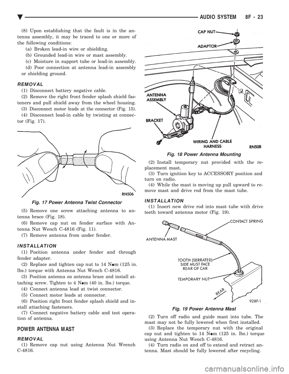
(4) Disconnect lead-in cable by twisting at connec-
tor (Fig. 17).
(5) Remove one screw attaching antenna to an-
tenna brace (Fig. 18). (6) Remove cap nut on fender surface with An-
tenna Nut Wench C-4816 (Fig. 11). (7) Remove antenna from under fender.
INSTALLATION
(1) Position antenna under fender and through
fender adapter. (2) Replace and tighten cap nut to 14 N Im (125 in.
lbs.) torque with Antenna Nut Wench C-4816.
(3) Position antenna on antenna brace and install at-
taching screw. Tighten to 4 N Im (40 in. lbs.) torque.
(4) Connect antenna lead at twist connector.
(5) Connect motor leads at connector.
(6) Position right front fender splash shield and in-
stall attaching fasteners. (7) Connect negative battery cable and test opera-
tion of antenna.
POWER ANTENNA MAST
REMOVAL
(1) Remove cap nut using Antenna Nut Wrench
C-4816. (2) Install temporary nut provided with the re-
placement mast. (3) Turn ignition key to ACCESSORY position and
turn on radio. (4) While the mast is moving up pull upward to re-
move mast and drive rod from the mast tube.
INSTALLATION
(1) Insert new drive rod into mast tube with drive
teeth toward antenna motor (Fig. 19).
(2) Turn off radio and guide mast into tube. The
mast may not be fully lowered when first installed. (3) Replace the temporary nut with the original
cap nut and tighten to 14 N Im (125 in. lbs.) torque
using Antenna Nut Wench C-4816. (4) Turn radio on and off to extend and retract an-
tenna. Mast should be fully lowered after recycling.
Fig. 18 Power Antenna Mounting
Fig. 17 Power Antenna Twist Connector
Fig. 19 Power Antenna Mast
Ä AUDIO SYSTEM 8F - 23