turn signal CHEVROLET DYNASTY 1993 User Guide
[x] Cancel search | Manufacturer: CHEVROLET, Model Year: 1993, Model line: DYNASTY, Model: CHEVROLET DYNASTY 1993Pages: 2438, PDF Size: 74.98 MB
Page 269 of 2438
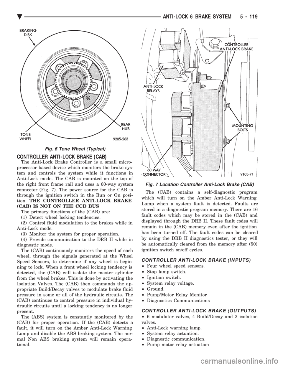
CONTROLLER ANTI-LOCK BRAKE (CAB)
The Anti-Lock Brake Controller is a small micro-
processor based device which monitors the brake sys-
tem and controls the system while it functions in
Anti-Lock mode. The CAB is mounted on the top of
the right front frame rail and uses a 60-way system
connector (Fig. 7). The power source for the CAB is
through the ignition switch in the Run or On posi-
tion. THE CONTROLLER ANTI-LOCK BRAKE
(CAB) IS NOT ON THE CCD BUS The primary functions of the (CAB) are:
(1) Detect wheel locking tendencies.
(2) Control fluid modulation to the brakes while in
Anti-Lock mode. (3) Monitor the system for proper operation.
(4) Provide communication to the DRB II while in
diagnostic mode. The (CAB) continuously monitors the speed of each
wheel, through the signals generated at the Wheel
Speed Sensors, to determine if any wheel is begin-
ning to lock. When a front wheel locking tendency is
detected, the (CAB) will isolate the master cylinder
from the wheel brakes. This is done by activating the
Isolation Valves. The (CAB) then commands the ap-
propriate Build/Decay valves to modulate brake fluid
pressure in some or all of the hydraulic circuits. The
(CAB) continues to control pressure in individual hy-
draulic circuits until a locking tendency is no longer
present. The (ABS) system is constantly monitored by the
(CAB) for proper operation. If the (CAB) detects a
fault, it will turn on the Amber Anti-Lock Warning
Lamp and disable the ABS braking system. The nor-
mal Non ABS braking system will remain opera-
tional. The (CAB) contains a self-diagnostic program
which will turn on the Amber Anti-Lock Warning
Lamp when a system fault is detected. Faults are
stored in a diagnostic program memory. There are 16
fault codes which may be stored in the (CAB) and
displayed through the DRB II. These fault codes will
remain in the (CAB) memory even after the ignition
has been turned off. The fault codes can be cleared
by using the DRB II diagnostics tester, or they will
be automatically cleared from the memory after (50)
ignition switch on/off cycles.
CONTROLLER ANTI-LOCK BRAKE (INPUTS)
² Four wheel speed sensors.
² Stop lamp switch.
² Ignition switch.
² System relay voltage.
² Ground.
² Pump/Motor Relay Monitor
² Diagnostics Communications
CONTROLLER ANTI-LOCK BRAKE (OUTPUTS)
²6 modulator valves, 4 Build/Decay and 2 isolation
valves.
² Anti-Lock warning lamp.
² System relay actuation.
² Diagnostic communication.
² Pump motor relay actuation
Fig. 6 Tone Wheel (Typical)
Fig. 7 Location Controller Anti-Lock Brake (CAB)
Ä ANTI-LOCK 6 BRAKE SYSTEM 5 - 119
Page 305 of 2438
(4) Provide communication to the DRB II while in
the Antilock brakes diagnostic mode. The CAB continuously monitors the speed of each
wheel, through the signals generated at the Wheel
Speed Sensors. This is used to determine if any
wheel of the vehicle is beginning to lock-up (skid)
when the brakes are applied. When a wheel locking
tendency is detected during brake apply. The CAB
commands the appropriate Build/Decay valves to
modulate brake fluid pressure in some or all of the
hydraulic circuits. The CAB continues to control
pressure in individual hydraulic circuits until a lock-
ing tendency is no longer present. The ABS system is constantly monitored by the
CAB for proper operation. If the CAB detects a fault,
it will turn on the Amber Antilock Warning Lamp
and disable the ABS brake system. The normal Non
ABS brake system will remain operational. The CAB contains a self-diagnostic program which
will turn on the Amber Antilock Warning Lamp
when a system fault is detected. Faults are stored in
a diagnostic program memory. There are 16 fault
codes which may be stored in the CAB and displayed
through the DRB II. These fault codes will remain in
the CAB memory even after the ignition has been
turned off. The fault codes can be cleared by using
the DRB II diagnostics tester, or they will be auto-
matically cleared from the memory after (50) ignition
switch on/off cycles.
CONTROLLER ANTILOCK BRAKE (INPUTS)
² Four wheel speed sensors.
² Stop lamp switch.
² Ignition switch.
² System relay voltage.
² Ground.
² Pump/Motor Relay Monitor
² Diagnostics Communications
CONTROLLER ANTILOCK BRAKE (OUTPUTS)
²4 Build/Decay valves.
² Antilock warning lamp.
² System relay actuation.
² Diagnostic communication.
² Pump/Motor relay actuation
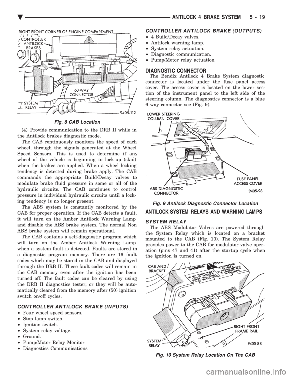
DIAGNOSTIC CONNECTOR
The Bendix Antilock 4 Brake System diagnostic
connector is located under the fuse panel access
cover. The access cover is located on the lower sec-
tion of the instrument panel to the left side of the
steering column. The diagnostics connector is a blue
6 way connector see (Fig. 9).
ANTILOCK SYSTEM RELAYS AND WARNING LAMPS
SYSTEM RELAY
The ABS Modulator Valves are powered through
the System Relay which is located on a bracket
mounted to the CAB (Fig. 10). The System Relay
provides power to the CAB for modulator valve oper-
ation (pins 47 and 41) after the startup cycle when
the ignition is turned on.
Fig. 8 CAB Location
Fig. 9 Antilock Diagnostic Connector Location
Fig. 10 System Relay Location On The CAB
Ä ANTILOCK 4 BRAKE SYSTEM 5 - 19
Page 424 of 2438
VISUAL MESSAGES
Following are the visual messages and the condi-
tions under which, the messages will be given:
² Keys in ignition
² Exterior lamps on
These messages will appear if the conditions are
present and the driver's door is open while the igni-
tion switch is in the OFF, LOCK, or ACC positions.
A tone will sound until the condition is corrected or
the door is closed.
² Passenger door ajar
² Driver door ajar
² Trunk ajar
² Park brake engaged
² Right rear door ajar
² Left rear door ajar
These messages will appear if a condition is de-
tected after the vehicle is in motion. When the con-
dition is corrected, a short tone will sound to
acknowledge the action. LOW OIL PRESSURE
If this message is displayed while the vehicle is at
cruising speeds, immediate attention is required. If
this message appears at idle speed, increase the idle
speed and the message should go off. If the message
remains on, immediate attention is required. ENGINE TEMP CRITICAL
This message appears when a sensor has determined
that the engine coolant is overheating. If this message
comes on and stays on, immediate action is required.
COOLANT LEVEL LOW
LOW FUEL LEVEL
LOW BRAKE FLUID
WASHER FLUID LOW
These messages will appear if a continuous warn-
ing condition is detected while the engine is running.
Inspection is required. To clear this message from
the display, after the condition is corrected, the igni-
tion switch must be turned OFF. CHECK TRANS
This message will appear if a continuous warning
condition is detected while the engine is running. Im-
mediate attention is recommended. To clear this mes-
sage from the display, after the condition has been
corrected, the ignition switch must be turned OFF. VOLTAGE IMPROPER
This message will appear if a continuous warning
condition is detected. Immediate attention is re-
quired. To clear this message from the display, after
the condition has been corrected, the ignition switch
must be turned OFF. TURN SIGNAL ON
This message will appear if the turn signal is left
on while vehicle speed is over 15 mph and the vehi-
cle has traveled over one-half mile. FASTEN SEAT BELTS An intermittent chime tone will sound for several
seconds if the seat belt is not fastened. CHK ENGINE OIL LEVEL
If this message is delivered, a check of the engine
oil dipstick is suggested. To clear this message, after
the condition is corrected, the ignition switch must
be turned OFF. HEADLAMP OUT
BRAKE LAMP OUT
TAIL LAMP OUT
These conditions are monitored only when the lamps
are on. The message will remain, even after the lamp is
replaced, until the lamp is turned on and operates.
SERVICE REMINDER
The maintenance reminder statement is programmed
to provide general information only. Refer to Group 0,
Lubrication & Maintenance for specific vehicle require-
ments.
The service reminder message is displayed at 7,500
miles or 12 months intervals, which ever comes first. MONITORED SYSTEMS OK
If there is no warning condition to report, the mes-
sage Monitored Systems OK is displayed (Fig. 2).
AUTOMATIC CALIBRATION SET PROCEDURE
The engine compartment node will continuously
and automatically recalibrate the compass under nor-
mal driving conditions. As long as the vehicle is
turning, the engine compartment node will record
new compass data. This new data will be used to
recalibrate the compass at a rate of at least once per
full (360 degree) turn of the vehicle. Automatic cali-
bration does not require operator interface.
MANUAL CALIBRATION SET PROCEDURE
Manual compass calibration has been replaced by
automatic calibration set procedure. The manual cal-
ibration set procedure is available, but no longer
serves any useful purpose.
EVIC SELF CHECK DIAGNOSTICS
Ignition switch ON, the EVIC not displaying any
message, may imply a system failure and not an
EVIC failure. Turn the ignition OFF, close all vehi-
cle doors and wait at least 60 seconds before begin-
ning test. Turn ignition switch to the ON position.
Pressing the TEMP, FUEL and INFO buttons at the
same time shall provide the visual message MOD-
ULE SELF CHECK for two seconds. Following at
two second interval there will be messages:
² E2-0 SELF CHECK
² E3-0 SELF CHECK
² END OF SELF CHECK
Showing the microcomputer is working properly.
When the self check mode and message shows:
² E2-1
² E3-2
This would show a fault exists in the EVIC's micro-
computer and the EVIC should be replaced (Fig. 3).
8C - 8 OVERHEAD CONSOLE Ä
Page 431 of 2438
VISUAL MESSAGES
Following are the visual messages and the condi-
tions under which, the messages will be given:
² Keys in ignition
² Exterior lamps on
These messages will appear if the conditions are
present and the driver's door is open while the igni-
tion switch is in the OFF, LOCK, or ACC positions.
A tone will sound until the condition is corrected or
the door is closed.
² Passenger door ajar
² Driver door ajar
² Trunk ajar
² Park brake engaged
² Right rear door ajar
² Left rear door ajar
These messages will appear if a condition is de-
tected after the vehicle is in motion. When the con-
dition is corrected, a short tone will sound to
acknowledge the action. LOW OIL PRESSURE
If this message is displayed while the vehicle is at
cruising speeds, immediate attention is required. If
this message appears at idle speed, increase the idle
speed and the message should go off. If the message
remains on, immediate attention is required. ENGINE TEMP CRITICAL
This message appears when a sensor has deter-
mined that the engine coolant is overheating. If this
message comes on and stays on, immediate action is
required. COOLANT LEVEL LOW
LOW FUEL LEVEL
LOW BRAKE FLUID WASHER FLUID LOW
These messages will appear if a continuous warn-
ing condition is detected while the engine is running.
Inspection is required. To clear this message from
the display, after the condition is corrected, the igni-
tion switch must be turned OFF. CHECK TRANS
This message will appear if a continuous warning
condition is detected while the engine is running. Im-
mediate attention is recommended. To clear this mes-
sage from the display, after the condition has been
corrected, the ignition switch must be turned OFF. VOLTAGE IMPROPER
This message will appear if a continuous warning
condition is detected. Immediate attention is re-
quired. To clear this message from the display, after
the condition has been corrected, the ignition switch
must be turned OFF. TURN SIGNAL ON
This message will appear if the turn signal is left
on while vehicle speed is over 15 mph and the vehi-
cle has traveled over one-half mile. FASTEN SEAT BELTS
An intermittent chime tone will sound for several
seconds if the seat belt is not fastened. CHK ENGINE OIL LEVEL
If this message is delivered, a check of the engine
oil dipstick is suggested. To clear this message, after
the condition is corrected, the ignition switch must
be turned OFF. HEADLAMP OUT
BRAKE LAMP OUT
TAIL LAMP OUT
These conditions are monitored only when the
lamps are on. The message will remain, even after
the lamp is replaced, until the lamp is turned on and
operates. SERVICE REMINDER
The maintenance reminder statement is pro-
grammed to provide general information only. Refer
to Group 0, Lubrication & Maintenance for specific
vehicle requirements. The service reminder message is displayed at 7,500
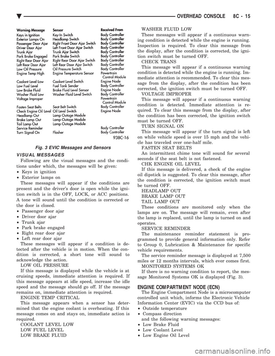
miles or 12 months intervals, which ever comes first. MONITORED SYSTEMS OK
If there is no warning condition to report, the mes-
sage Monitored Systems OK is displayed (Fig. 3).
ENGINE COMPARTMENT NODE (ECN)
The Engine Compartment Node is a microcomputer
controlled unit which, informs the Electronic Vehicle
Information Center (EVIC) via the CCD bus of:
² Outside temperature
² Compass direction
and the following warning messages:
² Low Brake Fluid
² Low Coolant Level
² Low Engine Oil Level
Fig. 3 EVIC Messages and Sensors
Ä OVERHEAD CONSOLE 8C - 15
Page 474 of 2438
The coil's low primary resistance allows the PCM to
fully charge the coil for each firing.
COOLANT TEMPERATURE SENSOR
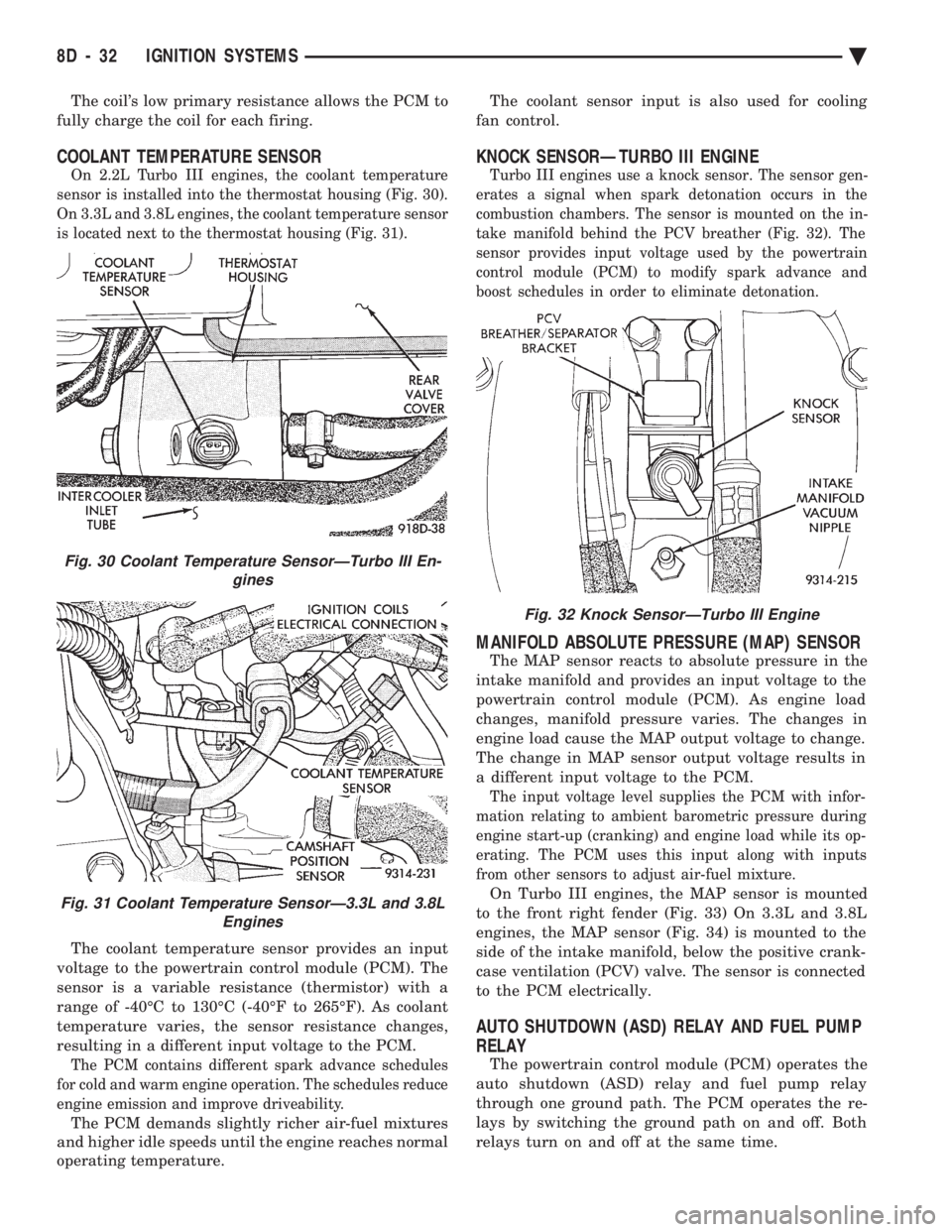
On 2.2L Turbo III engines, the coolant temperature
sensor is installed into the thermostat housing (Fig. 30).
On 3.3L and 3.8L engines, the coolant temperature sensor
is located next to the thermostat housing (Fig. 31).
The coolant temperature sensor provides an input
voltage to the powertrain control module (PCM). The
sensor is a variable resistance (thermistor) with a
range of -40ÉC to 130ÉC (-40ÉF to 265ÉF). As coolant
temperature varies, the sensor resistance changes,
resulting in a different input voltage to the PCM.
The PCM contains different spark advance schedules
for cold and warm engine operation. The schedules reduce
engine emission and improve driveability.
The PCM demands slightly richer air-fuel mixtures
and higher idle speeds until the engine reaches normal
operating temperature. The coolant sensor input is also used for cooling
fan control.
KNOCK SENSORÐTURBO III ENGINE
Turbo III engines use a knock sensor. The sensor gen-
erates a signal when spark detonation occurs in the
combustion chambers. The sensor is mounted on the in-
take manifold behind the PCV breather (Fig. 32). The
sensor provides input voltage used by the powertrain
control module (PCM) to modify spark advance and
boost schedules in order to eliminate detonation.
MANIFOLD ABSOLUTE PRESSURE (MAP) SENSOR
The MAP sensor reacts to absolute pressure in the
intake manifold and provides an input voltage to the
powertrain control module (PCM). As engine load
changes, manifold pressure varies. The changes in
engine load cause the MAP output voltage to change.
The change in MAP sensor output voltage results in
a different input voltage to the PCM.
The input voltage level supplies the PCM with infor-
mation relating to ambient barometric pressure during
engine start-up (cranking) and engine load while its op-
erating. The PCM uses this input along with inputs
from other sensors to adjust air-fuel mixture.
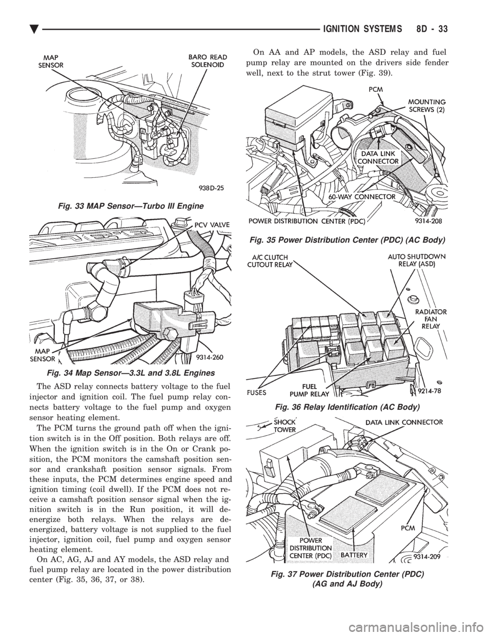
On Turbo III engines, the MAP sensor is mounted
to the front right fender (Fig. 33) On 3.3L and 3.8L
engines, the MAP sensor (Fig. 34) is mounted to the
side of the intake manifold, below the positive crank-
case ventilation (PCV) valve. The sensor is connected
to the PCM electrically.
AUTO SHUTDOWN (ASD) RELAY AND FUEL PUMP
RELAY
The powertrain control module (PCM) operates the
auto shutdown (ASD) relay and fuel pump relay
through one ground path. The PCM operates the re-
lays by switching the ground path on and off. Both
relays turn on and off at the same time.
Fig. 32 Knock SensorÐTurbo III Engine
Fig. 30 Coolant Temperature SensorÐTurbo III En- gines
Fig. 31 Coolant Temperature SensorÐ3.3L and 3.8LEngines
8D - 32 IGNITION SYSTEMS Ä
Page 475 of 2438
The ASD relay connects battery voltage to the fuel
injector and ignition coil. The fuel pump relay con-
nects battery voltage to the fuel pump and oxygen
sensor heating element. The PCM turns the ground path off when the igni-
tion switch is in the Off position. Both relays are off.
When the ignition switch is in the On or Crank po-
sition, the PCM monitors the camshaft position sen-
sor and crankshaft position sensor signals. From
these inputs, the PCM determines engine speed and
ignition timing (coil dwell). If the PCM does not re-
ceive a camshaft position sensor signal when the ig-
nition switch is in the Run position, it will de-
energize both relays. When the relays are de-
energized, battery voltage is not supplied to the fuel
injector, ignition coil, fuel pump and oxygen sensor
heating element. On AC, AG, AJ and AY models, the ASD relay and
fuel pump relay are located in the power distribution
center (Fig. 35, 36, 37, or 38). On AA and AP models, the ASD relay and fuel
pump relay are mounted on the drivers side fender
well, next to the strut tower (Fig. 39).
Fig. 33 MAP SensorÐTurbo III Engine
Fig. 34 Map SensorÐ3.3L and 3.8L Engines
Fig. 35 Power Distribution Center (PDC) (AC Body)
Fig. 36 Relay Identification (AC Body)
Fig. 37 Power Distribution Center (PDC) (AG and AJ Body)
Ä IGNITION SYSTEMS 8D - 33
Page 479 of 2438
FAILURE TO START TEST
This no-start test checks the camshaft position sen-
sor and crankshaft position sensor. The powertrain control module (PCM) supplies 8.0
volts to the camshaft position sensor and crankshaft
position sensor through one circuit. If the 8.0-volt
supply circuit shorts to ground, neither sensor will
produce a signal (output voltage to the PCM). When the ignition key is turned and left in the On
position , the PCM automatically energizes the auto shutdown (ASD) relay. However, the PCM de-energizes
the relay within one second because it has not received
a crankshaft position sensor signal indicating engine
rotation.
During cranking, the ASD relay will not energize
until the PCM receives a crankshaft signal. Secondly,
the ASD relay remains energized only if the PCM
senses a camshaft position sensor signal immediately
after detecting the crankshaft position sensor signal. (1) Check battery voltage. Voltage should approxi-
mately 12.66 volts or higher to perform failure to start
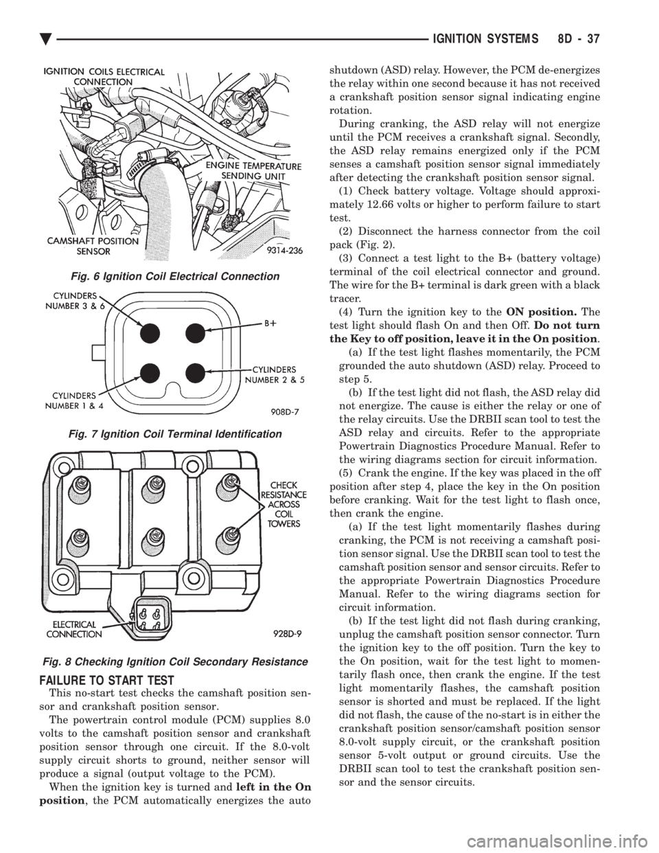
test. (2) Disconnect the harness connector from the coil
pack (Fig. 2). (3) Connect a test light to the B+ (battery voltage)
terminal of the coil electrical connector and ground.
The wire for the B+ terminal is dark green with a black
tracer. (4) Turn the ignition key to the ON position.The
test light should flash On and then Off. Do not turn
the Key to off position, leave it in the On position .
(a) If the test light flashes momentarily, the PCM
grounded the auto shutdown (ASD) relay. Proceed to
step 5. (b) If the test light did not flash, the ASD relay did
not energize. The cause is either the relay or one of
the relay circuits. Use the DRBII scan tool to test the
ASD relay and circuits. Refer to the appropriate
Powertrain Diagnostics Procedure Manual. Refer to
the wiring diagrams section for circuit information.
(5) Crank the engine. If the key was placed in the off
position after step 4, place the key in the On position
before cranking. Wait for the test light to flash once,
then crank the engine. (a) If the test light momentarily flashes during
cranking, the PCM is not receiving a camshaft posi-
tion sensor signal. Use the DRBII scan tool to test the
camshaft position sensor and sensor circuits. Refer to
the appropriate Powertrain Diagnostics Procedure
Manual. Refer to the wiring diagrams section for
circuit information. (b) If the test light did not flash during cranking,
unplug the camshaft position sensor connector. Turn
the ignition key to the off position. Turn the key to
the On position, wait for the test light to momen-
tarily flash once, then crank the engine. If the test
light momentarily flashes, the camshaft position
sensor is shorted and must be replaced. If the light
did not flash, the cause of the no-start is in either the
crankshaft position sensor/camshaft position sensor
8.0-volt supply circuit, or the crankshaft position
sensor 5-volt output or ground circuits. Use the
DRBII scan tool to test the crankshaft position sen-
sor and the sensor circuits.
Fig. 6 Ignition Coil Electrical Connection
Fig. 7 Ignition Coil Terminal Identification
Fig. 8 Checking Ignition Coil Secondary Resistance
Ä IGNITION SYSTEMS 8D - 37
Page 522 of 2438
(b) Refer to sending unit removal Group 14, Fuel.
(c) Connect sending unit wire and jumper wire
as described in the test procedure.
(5) If fuel gauge now checks within specifications,
original sending unit is electrically okay, check fol-
lowing as a possible cause: (a) Ground wire from sending unit to left side
cowl for continuity. (b) Sending unit deformed. Make sure sending
unit float arm moves freely and pick up tube is not
bent upwards creating an interference with bottom
of tank and inspect float. (c) Sending unit improperly installed. Install
properly. (d) Mounting flange on fuel tank for sending
unit deformed. Feel for interference fit of sending
unit to bottom of tank. It is permissible to bend
pick up tube down a little near mounting flange to
gain interference fit. (e) Fuel tank bottom deformed, causing improper
positioning of sending unit pick up tube. Replace or
repair tank and recheck sending unit.
GAUGE CALIBRATION
(1) Remove the gauge.
(2) Check for ignition voltage and ground to the
gauge. (3) With the ignition key in the OFF position, re-
place gauge. Turn the ignition key to the ON posi-
tion. To test oil pressure gauge engine must be
running. When testing oil or temperature gauge the
engine should be at normal operating temperature.
Record the gauge position. (4) Remove gauge and record the resistance be-
tween the sending unit pin and the gauge ground
pin. When checking gauges, it is important to have
the same engine temperature and speed when noting
gauge position. The time between gauge reading and
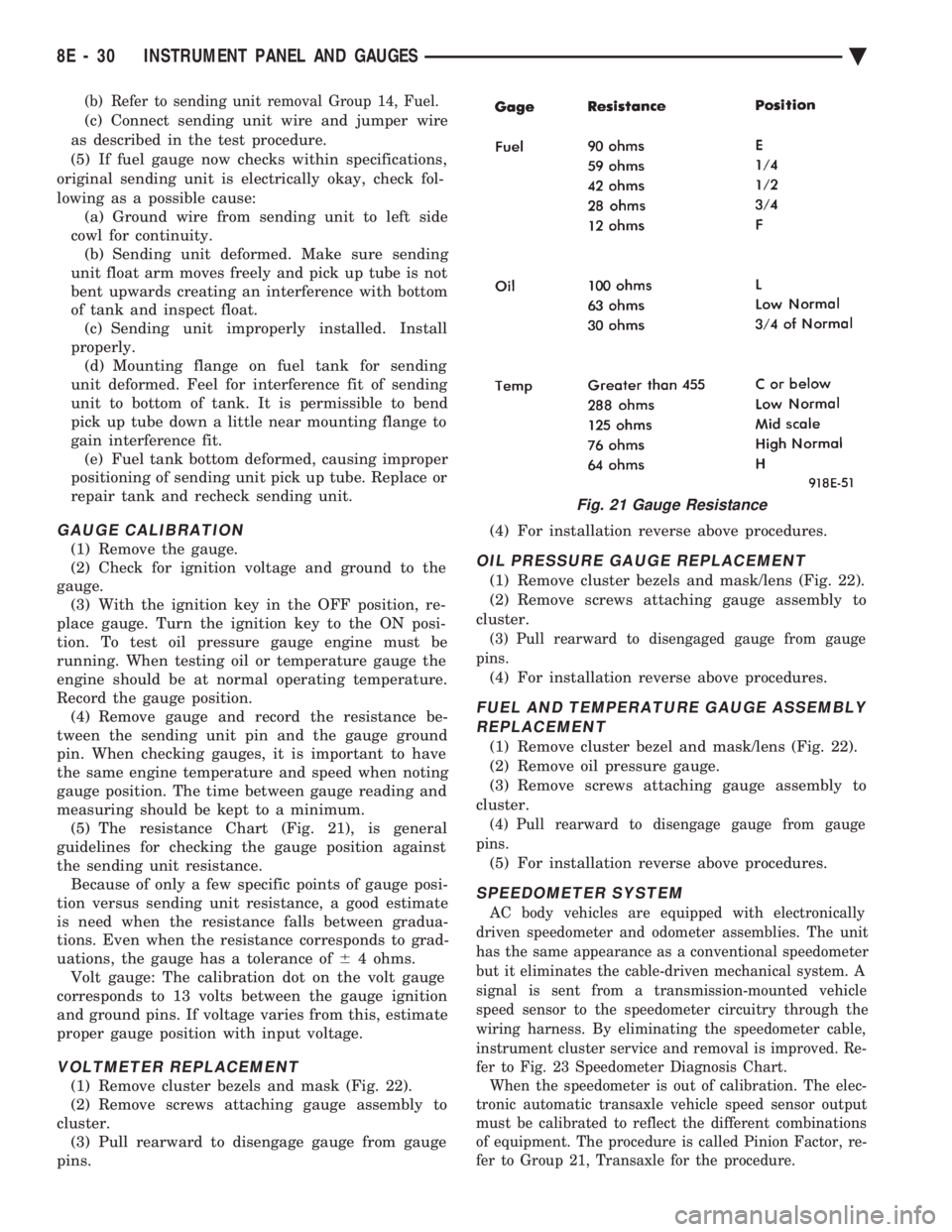
measuring should be kept to a minimum. (5) The resistance Chart (Fig. 21), is general
guidelines for checking the gauge position against
the sending unit resistance. Because of only a few specific points of gauge posi-
tion versus sending unit resistance, a good estimate
is need when the resistance falls between gradua-
tions. Even when the resistance corresponds to grad-
uations, the gauge has a tolerance of 64 ohms.
Volt gauge: The calibration dot on the volt gauge
corresponds to 13 volts between the gauge ignition
and ground pins. If voltage varies from this, estimate
proper gauge position with input voltage.
VOLTMETER REPLACEMENT
(1) Remove cluster bezels and mask (Fig. 22).
(2) Remove screws attaching gauge assembly to
cluster. (3) Pull rearward to disengage gauge from gauge
pins. (4) For installation reverse above procedures.
OIL PRESSURE GAUGE REPLACEMENT
(1) Remove cluster bezels and mask/lens (Fig. 22).
(2) Remove screws attaching gauge assembly to
cluster.
(3) Pull rearward to disengaged gauge from gauge
pins.
(4) For installation reverse above procedures.
FUEL AND TEMPERATURE GAUGE ASSEMBLY REPLACEMENT
(1) Remove cluster bezel and mask/lens (Fig. 22).
(2) Remove oil pressure gauge.
(3) Remove screws attaching gauge assembly to
cluster.
(4) Pull rearward to disengage gauge from gauge
pins.
(5) For installation reverse above procedures.
SPEEDOMETER SYSTEM
AC body vehicles are equipped with electronically
driven speedometer and odometer assemblies. The unit
has the same appearance as a conventional speedometer
but it eliminates the cable-driven mechanical system. A
signal is sent from a transmission-mounted vehicle
speed sensor to the speedometer circuitry through the
wiring harness. By eliminating the speedometer cable,
instrument cluster service and removal is improved. Re-
fer to Fig. 23 Speedometer Diagnosis Chart. When the speedometer is out of calibration. The elec-
tronic automatic transaxle vehicle speed sensor output
must be calibrated to reflect the different combinations
of equipment. The procedure is called Pinion Factor, re-
fer to Group 21, Transaxle for the procedure.
Fig. 21 Gauge Resistance
8E - 30 INSTRUMENT PANEL AND GAUGES Ä
Page 543 of 2438
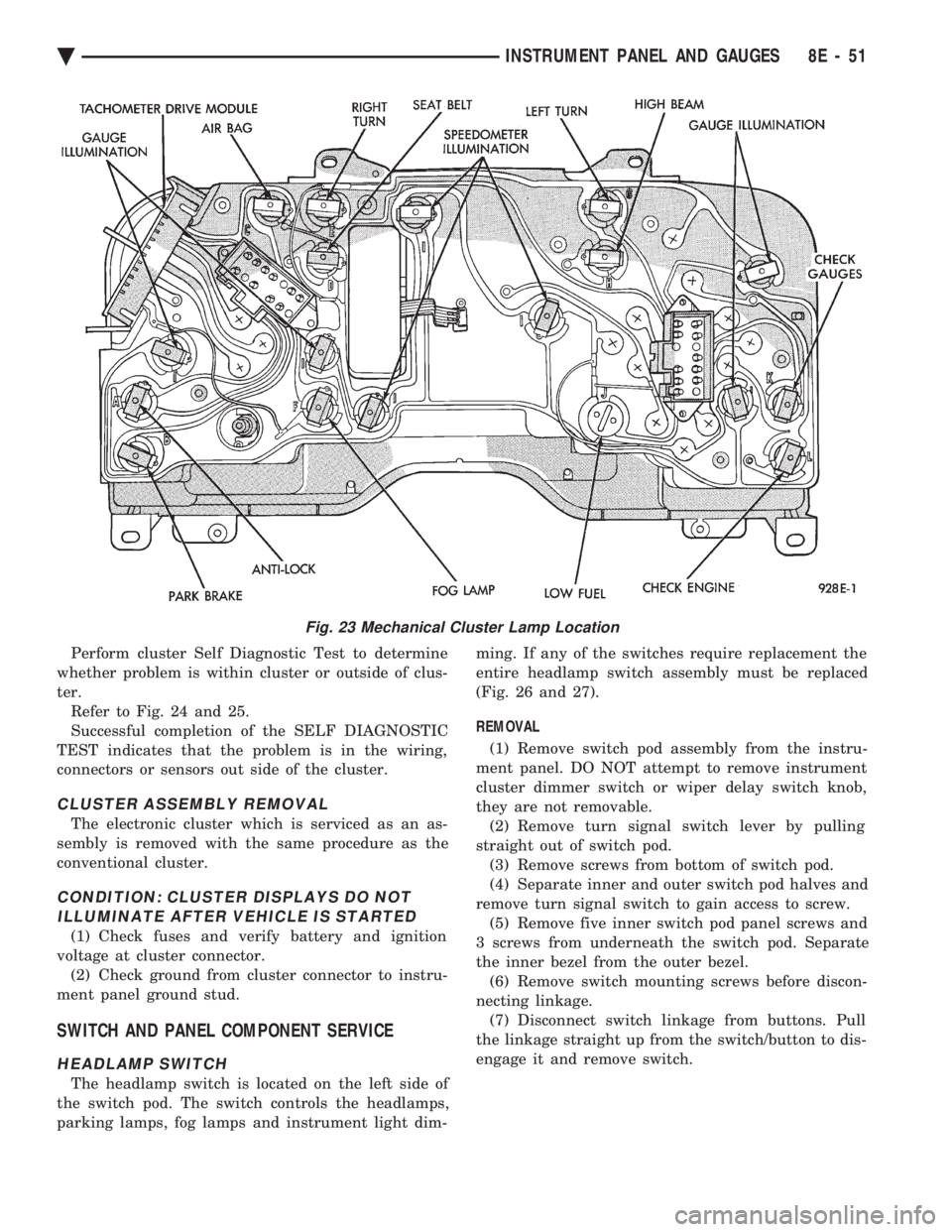
Perform cluster Self Diagnostic Test to determine
whether problem is within cluster or outside of clus-
ter. Refer to Fig. 24 and 25.
Successful completion of the SELF DIAGNOSTIC
TEST indicates that the problem is in the wiring,
connectors or sensors out side of the cluster.
CLUSTER ASSEMBLY REMOVAL
The electronic cluster which is serviced as an as-
sembly is removed with the same procedure as the
conventional cluster.
CONDITION: CLUSTER DISPLAYS DO NOT ILLUMINATE AFTER VEHICLE IS STARTED
(1) Check fuses and verify battery and ignition
voltage at cluster connector. (2) Check ground from cluster connector to instru-
ment panel ground stud.
SWITCH AND PANEL COMPONENT SERVICE
HEADLAMP SWITCH
The headlamp switch is located on the left side of
the switch pod. The switch controls the headlamps,
parking lamps, fog lamps and instrument light dim- ming. If any of the switches require replacement the
entire headlamp switch assembly must be replaced
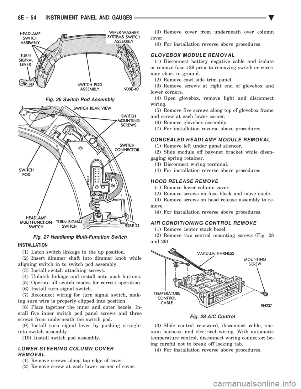
(Fig. 26 and 27).
REMOVAL
(1) Remove switch pod assembly from the instru-
ment panel. DO NOT attempt to remove instrument
cluster dimmer switch or wiper delay switch knob,
they are not removable. (2) Remove turn signal switch lever by pulling
straight out of switch pod. (3) Remove screws from bottom of switch pod.
(4) Separate inner and outer switch pod halves and
remove turn signal switch to gain access to screw. (5) Remove five inner switch pod panel screws and
3 screws from underneath the switch pod. Separate
the inner bezel from the outer bezel. (6) Remove switch mounting screws before discon-
necting linkage. (7) Disconnect switch linkage from buttons. Pull
the linkage straight up from the switch/button to dis-
engage it and remove switch.
Fig. 23 Mechanical Cluster Lamp Location
Ä INSTRUMENT PANEL AND GAUGES 8E - 51
Page 546 of 2438
INSTALLATION (1) Latch switch linkage in the up position.
(2) Insert dimmer shaft into dimmer knob while
aligning switch in to switch pod assembly. (3) Install switch attaching screws.
(4) Unlatch linkage and install onto push buttons.
(5) Operate all switch modes for correct operation.
(6) Install turn signal switch.
(7) Reconnect wiring for turn signal switch, mak-
ing sure wire is properly clipped into position. (8) Place together the inner and outer bezels. In-
stall five inner switch pod panel screws and three
screws from underneath the switch pod. (9) Install turn signal lever by pushing straight
into switch assembly. (10) Install switch pod assembly.
LOWER STEERING COLUMN COVER REMOVAL
(1) Remove screws along top edge of cover.
(2) Remove screw at each lower corner of cover. (3) Remove cover from underneath over column
cover. (4) For installation reverse above procedures.
GLOVEBOX MODULE REMOVAL
(1) Disconnect battery negative cable and isolate
or remove fuse #26 prior to removing switch or wires
may short to ground. (2) Remove cowl side trim panel.
(3) Remove screws at right end of glovebox and
lower corners. (4) Open glovebox, remove light and disconnect
wiring. (5) Remove five screws along top of glovebox frame
and screw at each lower corner. (6) Remove glovebox assembly.
(7) For installation reverse above procedures.
CONCEALED HEADLAMP MODULE REMOVAL
(1) Remove left under panel silencer.
(2) Slide module off bayonet bracket while disen-
gaging spring retainer. (3) Disconnect wiring terminal.
(4) For installation reverse above procedures.
HOOD RELEASE REMOVE
(1) Remove lower column cover.
(2) Remove screws on fuse block and move aside.
(3) Remove screws on hood release assembly to re-
move. (4) For installation reverse above procedures.
AIR CONDITIONING CONTROL REMOVE
(1) Remove center stack bezel.
(2) Remove two control mounting screws (Fig. 28
and 29).
(3) Slide control rearward, disconnect cable, vac-
uum harness, and electrical wiring. With automatic
temperature control, disconnect wiring connector; be-
ing careful not to break off locking tab. (4) For installation reverse above procedures.
Fig. 26 Switch Pod Assembly
Fig. 27 Headlamp Multi-Function Switch
Fig. 28 A/C Control
8E - 54 INSTRUMENT PANEL AND GAUGES Ä