ECO mode CHEVROLET DYNASTY 1993 Service Manual
[x] Cancel search | Manufacturer: CHEVROLET, Model Year: 1993, Model line: DYNASTY, Model: CHEVROLET DYNASTY 1993Pages: 2438, PDF Size: 74.98 MB
Page 24 of 2438
CHRYSLER
CORPORATION
SERVICE MANUAL
SUPPLEMENT
BENDIX ANTILOCK 4 BRAKE SYSTEM
1993 FRONT WHEEL DRIVE CAR
This manual supplements the 1993 Front-
Wheel-Drive Car Service Manual 81-270-3101,
and contains the service information on the new
Bendix Antilock 4 brake system. The Bendix
Antilock 4 brake system only affects the LeBaron
Landau, Spirit, Acclaim and LeBaron Coupe and
Convertible built at the Newark Assembly Plant
after April 19, 1993. Any of these model vehicles
built at other assembly plants, will continue to
use carryover antilock brake systems for the
remainder of the 1993 model year.
To order the special service tools used and
illustrated, please refer to the instructions on
inside back cover.
NO PART
OF THIS PUBLICATION MAY BE REPRO-
DUCED, STORED IN A RETRIEVAL SYSTEM,
OR TRANSMITTED, IN ANY FORM OR BY ANY
MEANS, ELECTRONIC, MECHANICAL, PHO-
TOCOPYING, RECORDING, OR OTHERWISE,
WITHOUT THE PRIOR WRITTEN PERMIS-
SION OF CHRYSLER CORPORATION.
Chrysler Corporation reserves the right to make changes in design or to make
additions to or improvements in its products without imposing any obligations
upon itself to install them on its products previously manufactured.
Litho in U.S.A. Copyright 1993 Chrysler Corporation 30M0393
NEXT PAGE ©
Page 50 of 2438
PCV SYSTEM TEST
Refer to group 25, Emission Control System for
proper procedures to test PCV system.
FUEL RECOMMENDATIONS
Chrysler Corporation recommends that only fuel pur-
chased from a reputable retailer be used. Use high qual-
ity, unleaded gasoline to provide satisfactory
driveability and highest fuel economy. Gasoline contain-
ing detergent and corrosion control additives are desire-
able. If the engine develops spark knock (audible ping),
poor performance, hard starting or stalling, purchase
fuel from another source. Engine performance can vary
when using different brands of gasoline with the same
octane rating. Occasional light engine spark knock un-
der heavy acceleration, at low speed or when vehicle is
heavily loaded is not harmful. Extended periods of
spark knock under moderate acceleration or at cruising
speed can damage the engine. The cause of excessive
spark knock condition must be diagnosed and corrected.
For diagnostic procedures refer to Group 14, Fuel Sys-
tem and Powertrain Diagnostic Procedures manual.
SELECTING GASOLINE
CAUTION:Do not use fuel containing METHANOL
(methyl or wood alcohol), damage to fuel system
will result. Do not use leaded gasoline, damage to catalytic
converter will result and vehicle will not conform to
emission control standards.
ETHANOL, MTBE OR ETBE BLENDS
All Chrysler Corporation vehicles are designed to
use unleaded gasoline ONLY. Gasohol blends, con-
taining 10% Ethanol (ethyl or grain alcohol) 90% un-
leaded gasoline can be used provided it has adequate
octane rating. Fuel blends containing up to 15% MTBE (Methyl
Tertiary Butyl Ether) and 85% unleaded gasoline can
be used. Fuel blends containing up to 17% ETBE
(Ethyl Tertiary Butyl Ether) and 83% unleaded gas-
oline can also be used. Fuel blended with ethanol, MTBE or ETBE are
also referred to as reformulated or clean air gasoline.
These fuels contribute less emissions to the atmo-
sphere. Chrysler Corporation recommends that
blended fuels be used when available
METHANOL BLENDS Using gasoline blended with methanol can result
in starting and driveability problems. Deterioration
of fuel system components will result. Methanol in-
duced problems are not the responsibility of Chrysler
Corporation and may not be covered by the vehicle
warranty. NON-TURBOCHARGED ENGINES
Use regular unleaded gasoline having a minimum
octane rating of 87 (R+M)/2. Higher octane premium
unleaded gasoline can be used if desired.
2.2L 16 VALVE TURBOCHARGED ENGINE
Use premium unleaded gasoline having a mini-
mum octane rating of 91 (R+M)/2. Gasoline with oc-
tane rating less than 91 (R+M)/2 can be used if
recommended gasoline is not available. Low octane
gasoline will reduce engine performance.
FLEXIBLE FUEL VEHICLES
CAUTION: Do not use 100% methanol, damage to
fuel system can result. Use unleaded regular gasoline having a minimum
octane rating of 87 (R=M)/2 and M85 fuel that is
85% methanol and 15% unleaded gasoline, or a mix-
ture of these two.
FUEL FILTER
The fuel filter requires service only when a fuel
contamination problem is suspected. For proper diag-
nostic and service procedures refer to Group 14, Fuel
System,
IGNITION CABLES, DISTRIBUTOR CAP, AND
ROTOR
Inspect and test ignition cables, distributor cap and
rotor when the spark plugs are replaced. Oil and
grime should be cleaned from the ignition cables and
distributor cap to avoid possible spark plug fouling.
Mopar, Foamy Engine Degreaser, or equivalent is
recommended for cleaning the engine compartment.
For proper service and diagnostic procedures refer to
Group 8D, Ignition System.
SPARK PLUGS
Ignition spark plugs should be replaced at the
mileage interval described in the Lubrication and
Maintenance Schedules. Refer to the General Infor-
mation section of this group. For proper service pro-
cedures refer to Group 8D, Ignition Systems.
DRIVE BELTS
Inspect and adjust drive belts at the interval de-
scribed in the Lubrication and Maintenance Sched-
ules. Refer to General Information section of this
group. For proper inspection and adjustment proce-
dures, see Group 7, Cooling System.
EMISSION CONTROL SYSTEM
Inspect all emission control components and hoses
when other under hood service is performed. Refer to
emission system Vacuum Hose Label located on the
0 - 14 LUBRICATION AND MAINTENANCE Ä
Page 89 of 2438
DRIVESHAFT RECONDITIONING PROCEDURE
Driveshaft reconditioning and/or boot replacement
for all front wheel drive vehicles is essentially the same
per C/V joint. Note: that lubricant requirements and quanti-
ties are different for Inner Joints than for Outer
Joints, and type being serviced. Use only the
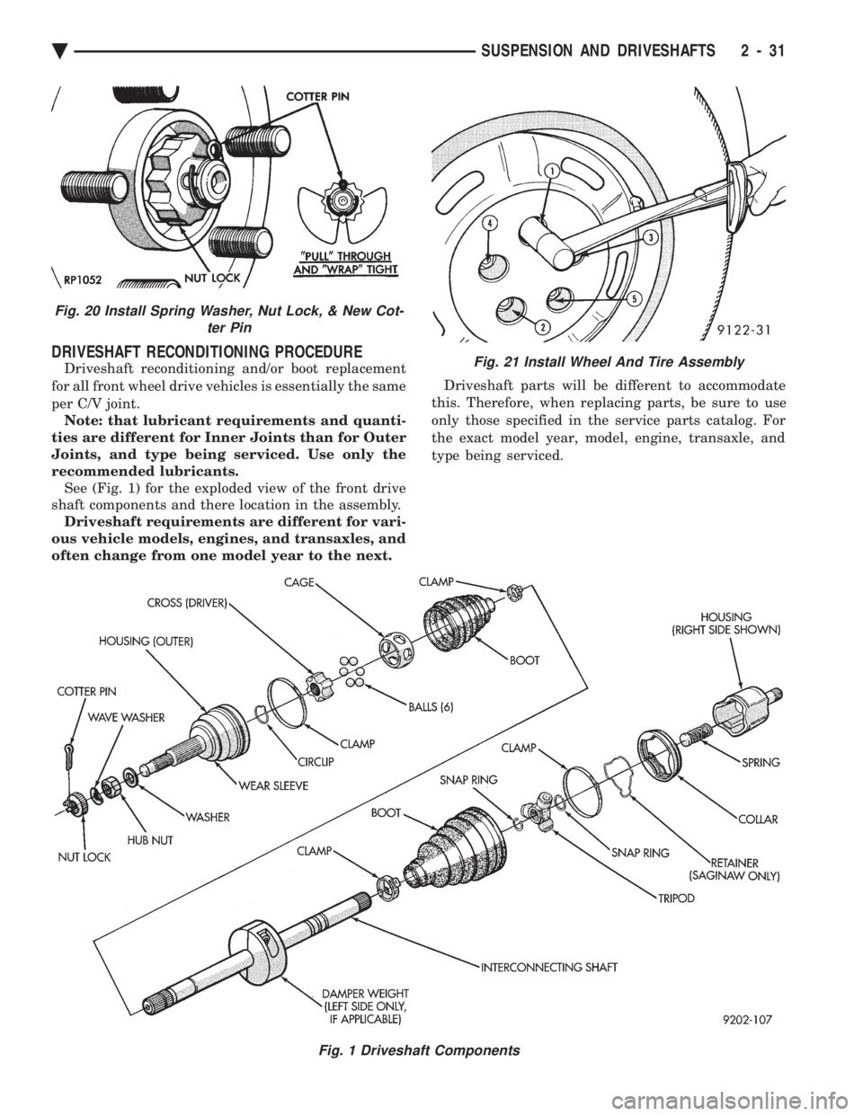
recommended lubricants. See (Fig. 1) for the exploded view of the front drive
shaft components and there location in the assembly. Driveshaft requirements are different for vari-
ous vehicle models, engines, and transaxles, and
often change from one model year to the next. Driveshaft parts will be different to accommodate
this. Therefore, when replacing parts, be sure to use
only those specified in the service parts catalog. For
the exact model year, model, engine, transaxle, and
type being serviced.
Fig. 1 Driveshaft Components
Fig. 21 Install Wheel And Tire Assembly
Fig. 20 Install Spring Washer, Nut Lock, & New Cot- ter Pin
Ä SUSPENSION AND DRIVESHAFTS 2 - 31
Page 147 of 2438
REAR (STUB) AXLE ALIGNMENT ALL MODELS INDEX
page page
General Information ....................... 89 Rear Wheel Alignment..................... 89
GENERAL INFORMATION
Because front wheel drive vehicles are equipped with
rear suspension incorporating stub axles (or wheel
spindles). It is possible to align both the camber and toe
of the rear wheels.
REAR WHEEL ALIGNMENT
Alignment adjustment if required. Is made by adding
0.010 inch shims (from the service package kit) be-
tween the spindle mounting surface and axle mounting
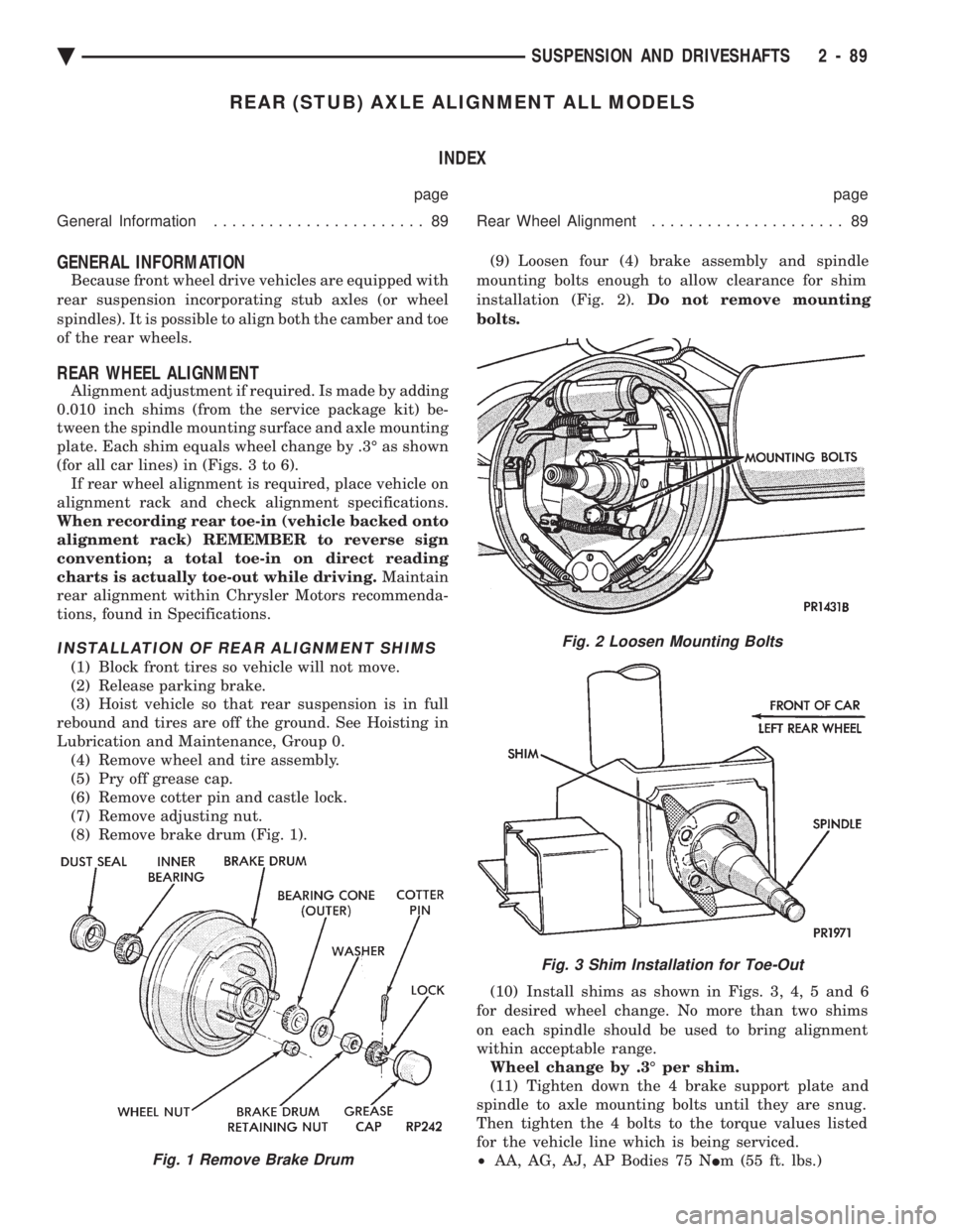
plate. Each shim equals wheel change by .3É as shown
(for all car lines) in (Figs. 3 to 6). If rear wheel alignment is required, place vehicle on
alignment rack and check alignment specifications.
When recording rear toe-in (vehicle backed onto
alignment rack) REMEMBER to reverse sign
convention; a total toe-in on direct reading
charts is actually toe-out while driving. Maintain
rear alignment within Chrysler Motors recommenda-
tions, found in Specifications.
INSTALLATION OF REAR ALIGNMENT SHIMS
(1) Block front tires so vehicle will not move.
(2) Release parking brake.
(3) Hoist vehicle so that rear suspension is in full
rebound and tires are off the ground. See Hoisting in
Lubrication and Maintenance, Group 0. (4) Remove wheel and tire assembly.
(5) Pry off grease cap.
(6) Remove cotter pin and castle lock.
(7) Remove adjusting nut.
(8) Remove brake drum (Fig. 1). (9) Loosen four (4) brake assembly and spindle
mounting bolts enough to allow clearance for shim
installation (Fig. 2). Do not remove mounting
bolts.
(10) Install shims as shown in Figs. 3, 4, 5 and 6
for desired wheel change. No more than two shims
on each spindle should be used to bring alignment
within acceptable range. Wheel change by .3É per shim.
(11) Tighten down the 4 brake support plate and
spindle to axle mounting bolts until they are snug.
Then tighten the 4 bolts to the torque values listed
for the vehicle line which is being serviced.
² AA, AG, AJ, AP Bodies 75 N Im (55 ft. lbs.)
Fig. 2 Loosen Mounting Bolts
Fig. 3 Shim Installation for Toe-Out
Fig. 1 Remove Brake Drum
Ä SUSPENSION AND DRIVESHAFTS 2 - 89
Page 230 of 2438
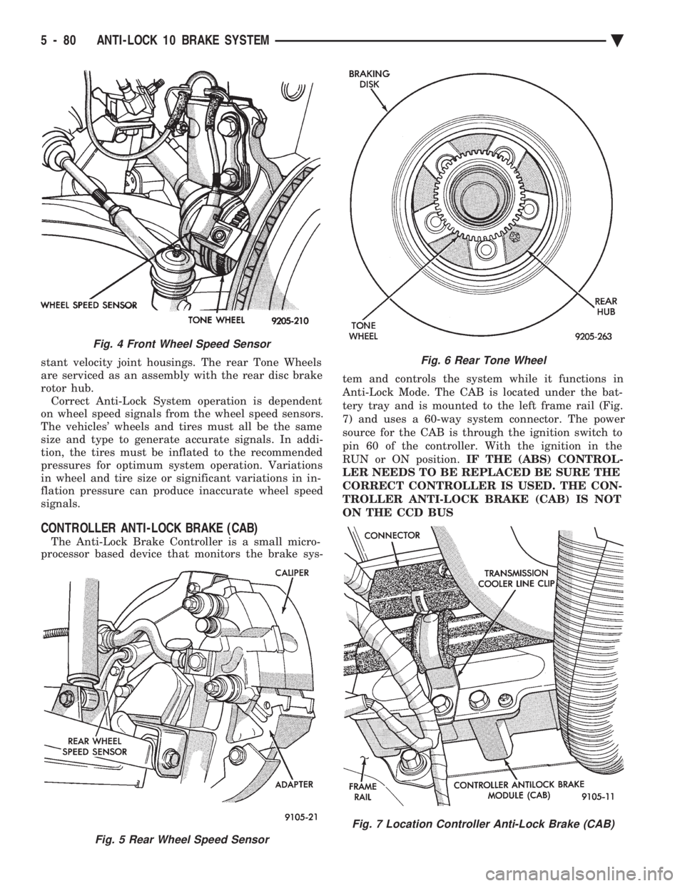
stant velocity joint housings. The rear Tone Wheels
are serviced as an assembly with the rear disc brake
rotor hub. Correct Anti-Lock System operation is dependent
on wheel speed signals from the wheel speed sensors.
The vehicles' wheels and tires must all be the same
size and type to generate accurate signals. In addi-
tion, the tires must be inflated to the recommended
pressures for optimum system operation. Variations
in wheel and tire size or significant variations in in-
flation pressure can produce inaccurate wheel speed
signals.
CONTROLLER ANTI-LOCK BRAKE (CAB)
The Anti-Lock Brake Controller is a small micro-
processor based device that monitors the brake sys- tem and controls the system while it functions in
Anti-Lock Mode. The CAB is located under the bat-
tery tray and is mounted to the left frame rail (Fig.
7) and uses a 60-way system connector. The power
source for the CAB is through the ignition switch to
pin 60 of the controller. With the ignition in the
RUN or ON position. IF THE (ABS) CONTROL-
LER NEEDS TO BE REPLACED BE SURE THE
CORRECT CONTROLLER IS USED. THE CON-
TROLLER ANTI-LOCK BRAKE (CAB) IS NOT
ON THE CCD BUS
Fig. 5 Rear Wheel Speed Sensor
Fig. 4 Front Wheel Speed Sensor
Fig. 6 Rear Tone Wheel
Fig. 7 Location Controller Anti-Lock Brake (CAB)
5 - 80 ANTI-LOCK 10 BRAKE SYSTEM Ä
Page 235 of 2438
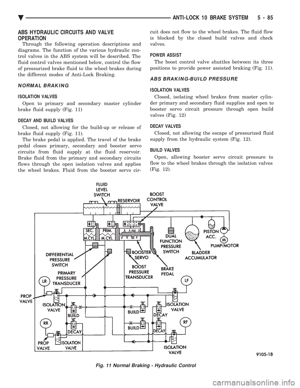
ABS HYDRAULIC CIRCUITS AND VALVE
OPERATION
Through the following operation descriptions and
diagrams. The function of the various hydraulic con-
trol valves in the ABS system will be described. The
fluid control valves mentioned below, control the flow
of pressurized brake fluid to the wheel brakes during
the different modes of Anti-Lock Braking.
NORMAL BRAKING
ISOLATION VALVES
Open to primary and secondary master cylinder
brake fluid supply (Fig. 11)
DECAY AND BUILD VALVES
Closed, not allowing for the build-up or release of
brake fluid supply (Fig. 11). The brake pedal is applied. The travel of the brake
pedal closes primary, secondary and booster servo
circuits from fluid supply at the fluid reservoir.
Brake fluid from the primary and secondary circuits
flows through the open isolation valves and applies
the wheel brakes. Fluid from the booster servo cir- cuit does not flow to the wheel brakes. The fluid flow
is blocked by the closed build valves and check
valves.
POWER ASSIST
The boost control valve shuttles between its three
positions to provide power assisted braking (Fig. 11).
ABS BRAKING-BUILD PRESSURE
ISOLATION VALVES
Closed, isolating wheel brakes from master cylin-
der primary and secondary fluid supplies and open to
booster servo circuit pressure through open build
valves (Fig. 12)
DECAY VALVES
Closed, not allowing the escape of pressurized fluid
supply from the hydraulic system (Fig. 12).
BUILD VALVES
Open, allowing booster servo circuit pressure to
flow to the wheel brakes through the isolation valves
(Fig. 12).
Fig. 11 Normal Braking - Hydraulic Control
Ä ANTI-LOCK 10 BRAKE SYSTEM 5 - 85
Page 239 of 2438
Brake Warning Lamp may indicate reduced
braking ability. The following procedure should
be used to test drive an ABS complaint:(1) Ignition on. Turn the ignition to the ON position
without starting the car and wait until the Red Brake
Warning Lamp and Amber Anti-Lock Warning Lamp
turn off. This will allow the pump to charge the
accumulator to operating pressure. If the warning
lamp(s) do not turn off, go to step 3. (2) Ignition off for 15 seconds.
(3) Start car. Wait for displays to return to normal
operating mode before proceeding. (4) With Shift lever in PARK, slowly depress brake
pedal and release. (5) Drive vehicle a short distance. During this test
drive, be sure that the vehicle achieves at least 20 mph.
Then brake to at least one complete stop and accelerate
slowly back up to at least 20 mph. (6) If a functional problem with the A.B.S. system is
determined while test driving a vehicle. Refer to the
Bendix Anti-Lock 10 Diagnostics Manual for required
test procedures and proper use of the DRB II tester.
CAUTION: The following are general precautions that
should be observed when servicing and diagnosing
the ABS system and/or other vehicle systems. Failure
to observe these precautions may result in ABS
system damage.
(1) If welding work is to be performed on the vehicle
using an arc welder, the (CAB) should be disconnected
before the welding operation begins. (2) The (CAB) and hydraulic assembly 10 way con-
nectors should never be connected or disconnected with
the ignition on. (3) Some components of the ABS system are not
serviced separately and must be serviced as complete
assemblies. Do not disassemble any component which
is designated as non-serviceable. (4) Always de-pressurize the Hydraulic Accu-
mulator when performing any work that re-
quires disconnecting any hydraulic tube, flex
hose or fitting. The ABS system uses brake fluid
at high pressure. Failure to de-pressurize the
accumulator may result in personal injury
and/or damage to painted surfaces. Brake fluid will damage painted surfaces. If brake
fluid is spilled on any painted surfaces, wash off with
water immediately.
DE-PRESSURIZING HYDRAULIC ACCUMULA- TOR
The ABS pump/motor assembly keeps the hydraulic
accumulator charged between approximately 11,032
and 13,790 kPa (1600 and 2000 psi) anytime key is in the ON position. The pump/motor assembly
cannot run if the ignition is off or either battery ca-
ble is disconnected. Unless otherwise specified, the hydraulic accumu-
lator should be de-pressurized before disassembling
any portion of the hydraulic system. The following
procedure should be used to de-pressurize the hy-
draulic accumulator: (1) With ignition off, or either battery cable discon-
nected, pump the brake pedal a minimum of 40 times
using approximately 50 pounds of pedal force. A no-
ticeable change in pedal feel will occur when the ac-
cumulator becomes discharged. (2) When a definite increase in pedal effort is felt,
pump the pedal a few additional times. This will in-
sure removal of all hydraulic pressure from the
brake system.
WHEEL SPEED SENSOR CABLES
Proper installation of wheel speed sensor cables is
critical to continued ABS system operation. Be sure
that cables are installed and routed properly. Failure
to install cables in their retainers, as shown in Sec-
tion 3 of this manual. May result in contact with
moving parts or over extension of cables, resulting in
an open circuit.
MECHANICAL DIAGNOSTICS AND SERVICE
PROCEDURES
SPECIAL SERVICE TOOLS
Some diagnostic procedures in this section require
the use of special service tools. Each of these tools is
described below.
DRB II DIAGNOSTIC TESTER
Some of the diagnostic procedures that are ex-
plained in this section require the use of the DRB II
DIAGNOSTICS TESTER to insure that proper diag-
nostics are performed. Refer to those sections for
proper testing procedures and the DRB II manual for
its proper operational information.
MST-6163 PRESSURE TESTER
Some diagnostic procedures in this manual require
the use of the MST-6163 pressure gauge and adaptor
(Fig. 2). Pressure Gauge, Special Tool MST-6163 is
required to measure accumulator pressure during
certain phases of ABS operation. The pressure gauge
and adaptor should be installed as follows: (1) De-pressurize the accumulator by pumping the
brake pedal a minimum of 40 times with the ignition
off. The procedure is fully explained under De-Pres-
surizing Hydraulic Accumulator which is described
earlier in this System Diagnosis Section.
Ä ANTI-LOCK 10 BRAKE SYSTEM 5 - 89
Page 264 of 2438
² PSIÐPounds per Square Inch (pressure)
² WSSÐWheel Speed Sensor
NORMAL BRAKING SYSTEM FUNCTION
Under normal braking conditions, the ABS System
functions the same as a standard brake system with
a diagonally split master cylinder and conventional
vacuum assist. If a wheel locking tendency is detected during a
brake application, the system will enter Anti-Lock
mode. During Anti-Lock Braking, hydraulic pressure
in the four wheel circuits is modulated to prevent
any wheel from locking. Each wheel circuit is de-
signed with a set of electrical valves and hydraulic
line to provide modulation, although for vehicle sta-
bility, both rear wheel valves receive the same elec-
trical signal. The system can build or reduce
pressure at each wheel, depending on signals gener-
ated by the wheel speed sensors (WSS) at each wheel
and received at the Controller Anti-Lock Brake
(CAB).
MAJOR COMPONENTS
The following is a list of major system components.
Details of all components can be found later in this
section. See (Fig. 1) for the general location of the
components in the vehicle.
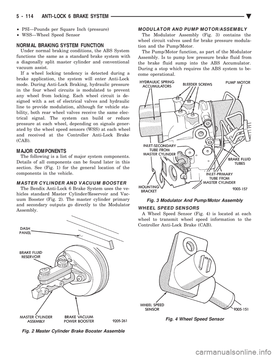
MASTER CYLINDER AND VACUUM BOOSTER
The Bendix Anti-Lock 6 Brake System uses the ve-
hicles standard Master Cylinder/Reservoir and Vac-
uum Booster (Fig. 2). The master cylinder primary
and secondary outputs go directly to the Modulator
Assembly.
MODULATOR AND PUMP MOTOR/ASSEMBLY
The Modulator Assembly (Fig. 3) contains the
wheel circuit valves used for brake pressure modula-
tion and the Pump/Motor. The Pump/Motor function, as part of the Modulator
Assembly. Is to pump low pressure brake fluid from
the brake fluid sump into the ABS Accumulator.
During a stop which requires the ABS system to be-
come operational.
WHEEL SPEED SENSORS
A Wheel Speed Sensor (Fig. 4) is located at each
wheel to transmit wheel speed information to the
Controller Anti-Lock Brake (CAB).
Fig. 2 Master Cylinder Brake Booster Assemble
Fig. 3 Modulator And Pump/Motor Assembly
Fig. 4 Wheel Speed Sensor
5 - 114 ANTI-LOCK 6 BRAKE SYSTEM Ä
Page 271 of 2438
Lamp Relay opens the Anti-Lock Warning Lamp Re-
lay switch. This breaks the ground path to the Am-
ber Anti-Lock Warning Lamp and the light is turned
off. The (CAB) by itself, also has the ability to turn on
the Amber Anti-Lock Warning Lamp. The (CAB) can
turn on the Amber Anti-Lock Warning Lamp by pro-
viding a ground at pin 15.
ANTI-LOCK WARNING LAMP ON
System Relay and Anti-Lock Warning Lamp
Relay De-Energized. When the Amber Anti-Lock Warning Lamp is on,
there is no electrical current flow from the (CAB) at
pin 57. The System Relay coil is NOT energized. No
electrical current flows to pin 47 and 41 (modulator
valve power), or to the Anti-Lock Warning Lamp Re-
lay coil. Thus, the Amber Anti-Lock Warning Lamp
is not energized. The Amber Anti-Lock Warning Lamp is grounded through the Anti-Lock Warning
Lamp Relay contacts. The Amber Anti-Lock Warning
Lamp is turned on.
HYDRAULIC CIRCUITS AND VALVE OPERATION
Through the following operation descriptions and
diagrams. The function of the various hydraulic con-
trol valves in the ABS system will be described. The
fluid control valves mentioned below, control the flow
of pressurized brake fluid to the wheel brakes during
the different modes of Anti-Lock braking. For explanation purposes we will assume all speed
sensors are sending the same wheel speed informa-
tion, requiring the same hydraulic fluid modulation
at the same rate.
NORMAL BRAKING
ISOLATION VALVES
Open to primary and secondary master cylinder
fluid supply (Fig. 1)
BUILD/DECAY VALVES Closed (Fig. 1)
The brake pedal is applied. The travel of the brake
pedal closes primary and secondary circuits from the
master cylinder fluid supply. Brake fluid from the
primary and secondary circuits flows through the
open isolation valves, through the build/decay valves
to the wheel brakes.
ABS BRAKING-BUILD PRESSURE
ISOLATION VALVES
Closed, isolating wheel brakes from master cylin-
der primary and secondary fluid supply. Through
open build valves (Fig. 2).
BUILD/DECAY VALVES Open (Fig. 2)
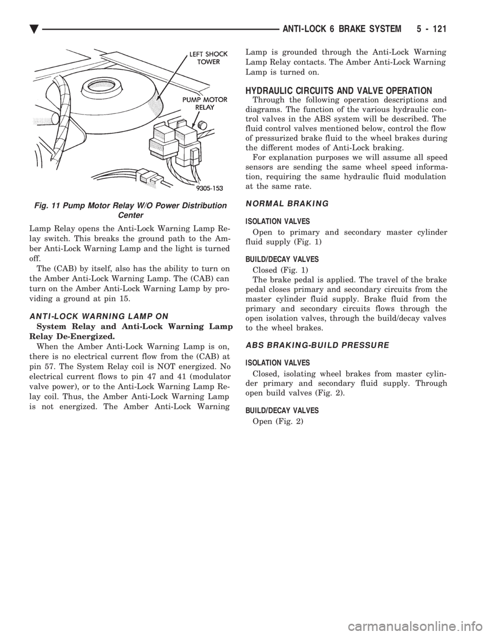
Fig. 11 Pump Motor Relay W/O Power Distribution Center
Ä ANTI-LOCK 6 BRAKE SYSTEM 5 - 121
Page 277 of 2438
WARNING: WHEN BLEEDING THE MODULATOR
ASSEMBLY WEAR SAFETY GLASSES. A CLEAR
BLEED TUBE MUST BE ATTACHED TO THE
BLEEDER SCREWS AND SUBMERGED IN A CLEAR
CONTAINER FILLED PART WAY WITH CLEAN
BRAKE FLUID. DIRECT THE FLOW OF BRAKE
FLUID AWAY FROM THE PAINTED SURFACES OF
THE VEHICLE. BRAKE FLUID AT HIGH PRESSURE
MAY COME OUT OF THE BLEEDER SCREWS,
WHEN OPENED.
When bleeding the Modulator Assembly. The fol-
lowing bleeding sequence MUSTbe followed to in-
sure complete and adequate bleeding of the brakes
hydraulic system. The Modulator Assembly can be
bled using a Manual bleeding procedure or standard
Pressure Bleeding Equipment. If the brake system is to be bled using pressure
bleeding equipment. Refer to Bleeding Brake System,
in the Service Adjustments section at the beginning
of this group, for proper equipment usage and proce-
dures.
MODULATOR ASSEMBLY BLEEDING SEQUENCE
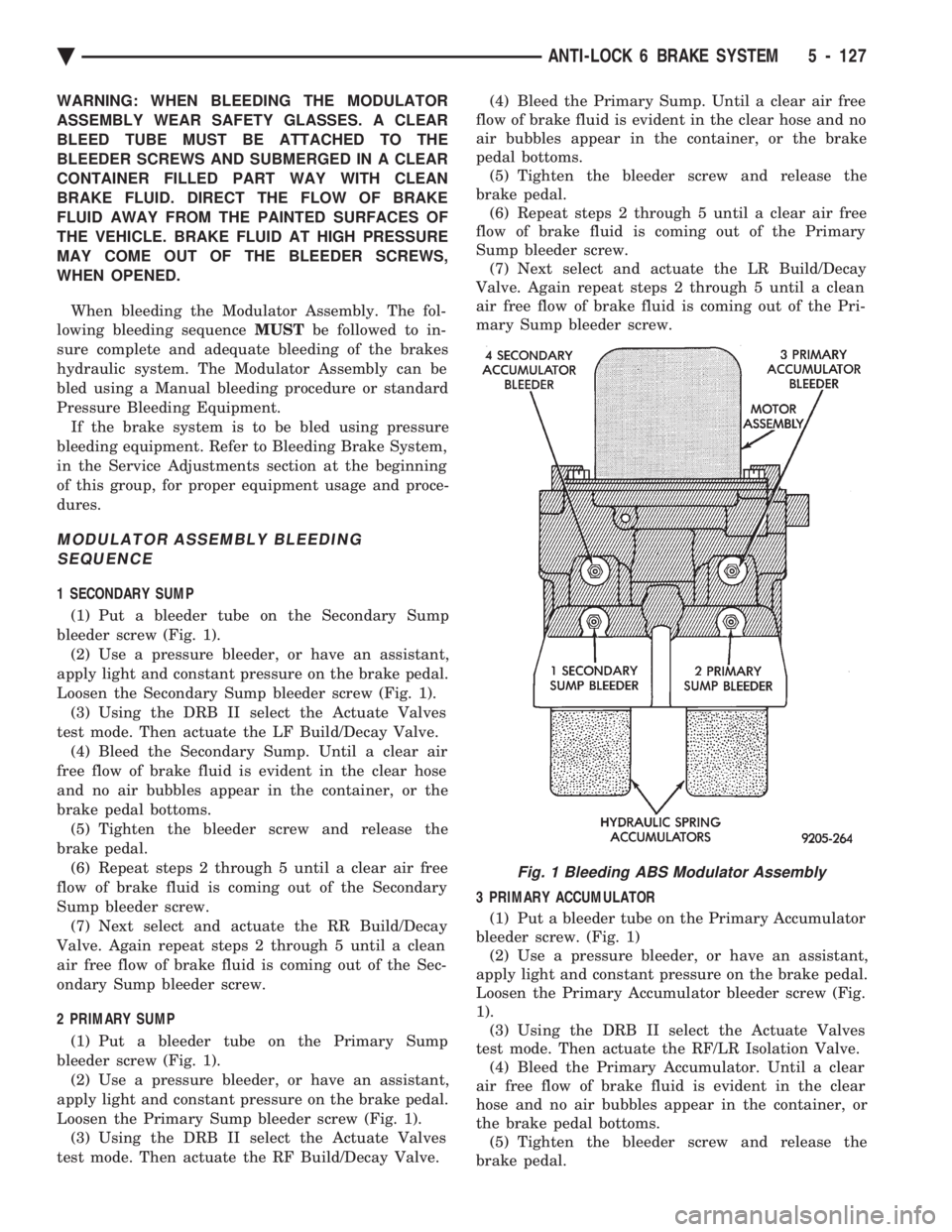
1 SECONDARY SUMP
(1) Put a bleeder tube on the Secondary Sump
bleeder screw (Fig. 1). (2) Use a pressure bleeder, or have an assistant,
apply light and constant pressure on the brake pedal.
Loosen the Secondary Sump bleeder screw (Fig. 1). (3) Using the DRB II select the Actuate Valves
test mode. Then actuate the LF Build/Decay Valve. (4) Bleed the Secondary Sump. Until a clear air
free flow of brake fluid is evident in the clear hose
and no air bubbles appear in the container, or the
brake pedal bottoms. (5) Tighten the bleeder screw and release the
brake pedal. (6) Repeat steps 2 through 5 until a clear air free
flow of brake fluid is coming out of the Secondary
Sump bleeder screw. (7) Next select and actuate the RR Build/Decay
Valve. Again repeat steps 2 through 5 until a clean
air free flow of brake fluid is coming out of the Sec-
ondary Sump bleeder screw.
2 PRIMARY SUMP
(1) Put a bleeder tube on the Primary Sump
bleeder screw (Fig. 1). (2) Use a pressure bleeder, or have an assistant,
apply light and constant pressure on the brake pedal.
Loosen the Primary Sump bleeder screw (Fig. 1). (3) Using the DRB II select the Actuate Valves
test mode. Then actuate the RF Build/Decay Valve. (4) Bleed the Primary Sump. Until a clear air free
flow of brake fluid is evident in the clear hose and no
air bubbles appear in the container, or the brake
pedal bottoms. (5) Tighten the bleeder screw and release the
brake pedal. (6) Repeat steps 2 through 5 until a clear air free
flow of brake fluid is coming out of the Primary
Sump bleeder screw. (7) Next select and actuate the LR Build/Decay
Valve. Again repeat steps 2 through 5 until a clean
air free flow of brake fluid is coming out of the Pri-
mary Sump bleeder screw.
3 PRIMARY ACCUMULATOR
(1) Put a bleeder tube on the Primary Accumulator
bleeder screw. (Fig. 1) (2) Use a pressure bleeder, or have an assistant,
apply light and constant pressure on the brake pedal.
Loosen the Primary Accumulator bleeder screw (Fig.
1). (3) Using the DRB II select the Actuate Valves
test mode. Then actuate the RF/LR Isolation Valve. (4) Bleed the Primary Accumulator. Until a clear
air free flow of brake fluid is evident in the clear
hose and no air bubbles appear in the container, or
the brake pedal bottoms. (5) Tighten the bleeder screw and release the
brake pedal.
Fig. 1 Bleeding ABS Modulator Assembly
Ä ANTI-LOCK 6 BRAKE SYSTEM 5 - 127