battery location CHEVROLET DYNASTY 1993 Owner's Manual
[x] Cancel search | Manufacturer: CHEVROLET, Model Year: 1993, Model line: DYNASTY, Model: CHEVROLET DYNASTY 1993Pages: 2438, PDF Size: 74.98 MB
Page 667 of 2438
EXTERIOR LAMP SYSTEMS INDEX
page page
Daytime Running LampÐCanada Only ........ 25
Headlamp Time Delay System .............. 26
Lamp Outage ModuleÐAA-Body ............. 25 Lamp Outage ModuleÐAll Except AA-Body
..... 25
Lamp Outage System ..................... 25
Removal (Fig. 4) ......................... 25
LAMP OUTAGE SYSTEM
Diagnostics and component relationships for AC,
AG, AJ or AY-Bodies can be found in the Body Di-
agnostic Procedures Manual, Electronic Vehicle In-
formation Center (EVIC) section. For circuit and component locations on AA-body,
refer to the Wiring Diagrams Manual.
LAMP OUTAGE MODULEÐALL EXCEPT AA-BODY
REMOVAL
(1) Remove battery negative cable.
(2) Remove the glove box assembly. Refer to Group
8E, Instrument Panel. (3) Disconnect the wire connector from the lamp
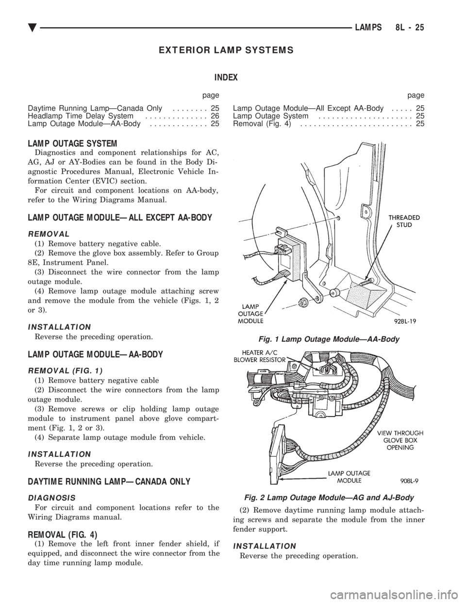
outage module. (4) Remove lamp outage module attaching screw
and remove the module from the vehicle (Figs. 1, 2
or 3).
INSTALLATION
Reverse the preceding operation.
LAMP OUTAGE MODULEÐAA-BODY
REMOVAL (FIG. 1)
(1) Remove battery negative cable
(2) Disconnect the wire connectors from the lamp
outage module. (3) Remove screws or clip holding lamp outage
module to instrument panel above glove compart-
ment (Fig. 1, 2 or 3). (4) Separate lamp outage module from vehicle.
INSTALLATION
Reverse the preceding operation.
DAYTIME RUNNING LAMPÐCANADA ONLY
DIAGNOSIS
For circuit and component locations refer to the
Wiring Diagrams manual.
REMOVAL (FIG. 4)
(1) Remove the left front inner fender shield, if
equipped, and disconnect the wire connector from the
day time running lamp module. (2) Remove daytime running lamp module attach-
ing screws and separate the module from the inner
fender support.INSTALLATION
Reverse the preceding operation.
Fig. 1 Lamp Outage ModuleÐAA-Body
Fig. 2 Lamp Outage ModuleÐAG and AJ-Body
Ä LAMPS 8L - 25
Page 695 of 2438
POWER LOCKS
CONTENTS
page page
CIRCUIT BREAKER TEST .................. 1
DECK LID OPERATION ................... 3
DECK LID PULL-DOWN SYSTEMÐAC and AY BODIES .............................. 3
DOOR LOCK INHIBIT ..................... 6
DOOR LOCK INHIBIT ..................... 1
DOOR LOCK MOTOR REPLACEMENT ........ 3
DOOR LOCK SYSTEM TEST ............... 3
ELECTRIC MOTOR TEST .................. 2 GENERAL INFORMATION
.................. 1
KEYLESS ENTRY SYSTEM ................ 1
LAMP OUTAGE MODULE REPLACEMENT .... 6
POWER DOOR LOCKS .................... 2
POWER PULL DOWN .................... 4
REMOTE KEYLESS ENTRY ................ 5
REMOTE KEYLESS MODULE REPLACEMENT . . 6
SWITCH TEST .......................... 1
WIRING VOLTAGE TEST .................. 1
GENERAL INFORMATION
All doors can be locked or unlocked electrically by
operating the switch on a front door panel or arm
rest. The rear doors can be locked or unlocked by actu-
ation of the front door switch, or can be locked or un-
locked mechanically and independently with their
respective locking knobs. The front doors can be locked or unlocked mechan-
ically with the locking knob regardless of electrical
locking and unlocking actuation with the front door
knobs. The right and left front door on all car lines can be
locked or unlocked mechanically from the outside
with the key or electrically as described above. The
left front can also be unlocked by actuation of the in-
side remote door handle. The right front door on AC,
AG, AJ and AY can be unlocked by actuation of the
inside remote door handle. The deck lid lock consists of a latch with internal
solenoid and push button switch. The solenoid is en-
ergized only when the push button is depressed.
DOOR LOCK INHIBIT
The power door lock inhibit system prevents the
doors from being locked using the power door locks
when either of two conditions occur: (1) The key is in the ignition switch and any of the
doors are open. The ignition switch does not have to
be ON. (2) The key is in the ignition switch and the head-
lamp are on.
KEYLESS ENTRY SYSTEM
The system allows locking and unlocking of vehicle
door(s) and Trunk lid by remote control using a hand
held radio transmitter. The ignition switch must be
OFF before the trunk lid can be unlocked with the
transmitter. The receiver may receive signals from two trans-
mitters. Each transmitter has its own code, and the
code has been stored in memory. If the transmitter is
replaced or a second transmitter is add, the code on
both units have to be placed in memory.
CIRCUIT BREAKER TEST
Find correct circuit breaker on fuse block. Pull out
slightly but be sure that circuit breaker terminals
still contact terminals in fuse block. Connect ground
wire of voltmeter to a good ground. With probe of
voltmeter positive wire, check both terminals of cir-
cuit breaker for 12 volts. If only one terminal checks
at 12 volts, circuit breaker is defective and must be
replaced. If neither terminal shows 12 volts, check
for open or shorted circuit to circuit breaker.
WIRING VOLTAGE TEST
The following wiring test sequence determines
whether or not voltage is continuous through the
body harness to switch. (1) Remove left side switch from trim panel.
(2) Carefully separate multiple terminal block on
wiring harness from switch body. (3) Connect one lead of test light to a ground ter-
minal:
² Black Wire AA and AC Bodies
² Gray wire AG and AJ Bodies
² Touch other test light lead to Red Wire terminal.
² If test light comes on, the wiring circuit between
the battery and switch is functional.
² If test light does not come on, check 30 amp circuit
breaker or for a open circuit.
SWITCH TEST
Remove the switch from its mounting location. Us-
ing an ohmmeter, refer to (Fig. 1) to determine if
continuity is correct in the Lock and Unlock switch
positions. If these results are not obtained, replace
the switch.
Ä POWER LOCKS 8P - 1
Page 720 of 2438
CONDITION: NO SEAT TRACK FRONT UP OR DOWN MOVEMENT IN THE RECALL MODE,SEAT TRACK FRONT WILL MOVE UP ORDOWN BY MANUAL SWITCH ACTUATIONWITHOUT STALL DETECTION.
PROCEDURE
(1) Check for a voltage at pin 2 of the control mod-
ule 21-way connector. Less than 5 volts for the seat
track front full up and more than 0 volts when fully
down. (2) Check for a voltage at pin 2 of the natural
5-way connector. Same as in step (1) above. With the
ground lead of the meter at pin 4 of this connector. If
the voltage reading is at 0 volts, disconnect the
5-way natural connector and check for a short to
ground in the harness. If no short is found, reconnect
the connector and continue the procedure. (3) Check for the voltage to vary as noted above, if
it does not vary as the seat track front is moved up
and down, the sensing potentiometer is defective. Re-
place the seat motor package assembly. After re-
placement of the seat motor package, reconnect all
wiring connectors and reinstall seat assembly in ve-
hicle. Operate the switches manually to cause maxi-
mum seat movement in all directions. Perform the
memory seat diagnostic self check so the control
module will learn the new soft limits of the assem-
bly.
CONDITION: NO SEAT TRACK REAR UP OR DOWN MOVEMENT IN THE RECALL MODE,SEAT TRACK REAR WILL MOVE UP OR DOWNBY MANUAL SWITCH ACTUATION WITHOUTSTALL DETECTION.
PROCEDURE
(1) Check for a voltage at pin 13 of the control
module 21-way connector. Less than 5 volts for the
seat track rear full up and more than 0 volts when
fully down. (2) Check for a voltage at pin 3 of the natural
5-way connector. Same as in step (1) above. The
ground lead connected to pin 4 of the 5-way connec-
tor. If the voltage reading is at 0 volts, disconnect
the 5-way natural connector and check for a short to
ground in the harness. If no short is found, reconnect
the connector and continue the procedure. (3) Check for the voltage to vary as noted above, if
it does not vary as the seat track rear is moved up
and down, the sensing potentiometer is defective. Re-
place the seat motor package assembly. After re-
placement of the seat motor package, reconnect all
wiring connectors and reinstall seat assembly in ve-
hicle. Operate the switches manually to cause maxi-
mum seat movement in all directions. Perform the
diagnostic self seat check so the control module will
learn the new soft limits of the assembly.
CONDITION: NO MOVEMENT OF THE SEAT,
SEAT WILL MOVE IN THE RECALL MODEONLY.
PROCEDURE
(1) Check for battery voltage to terminal 3 of driv-
er's power seat switch. (2) Check for continuity of driver's power seat
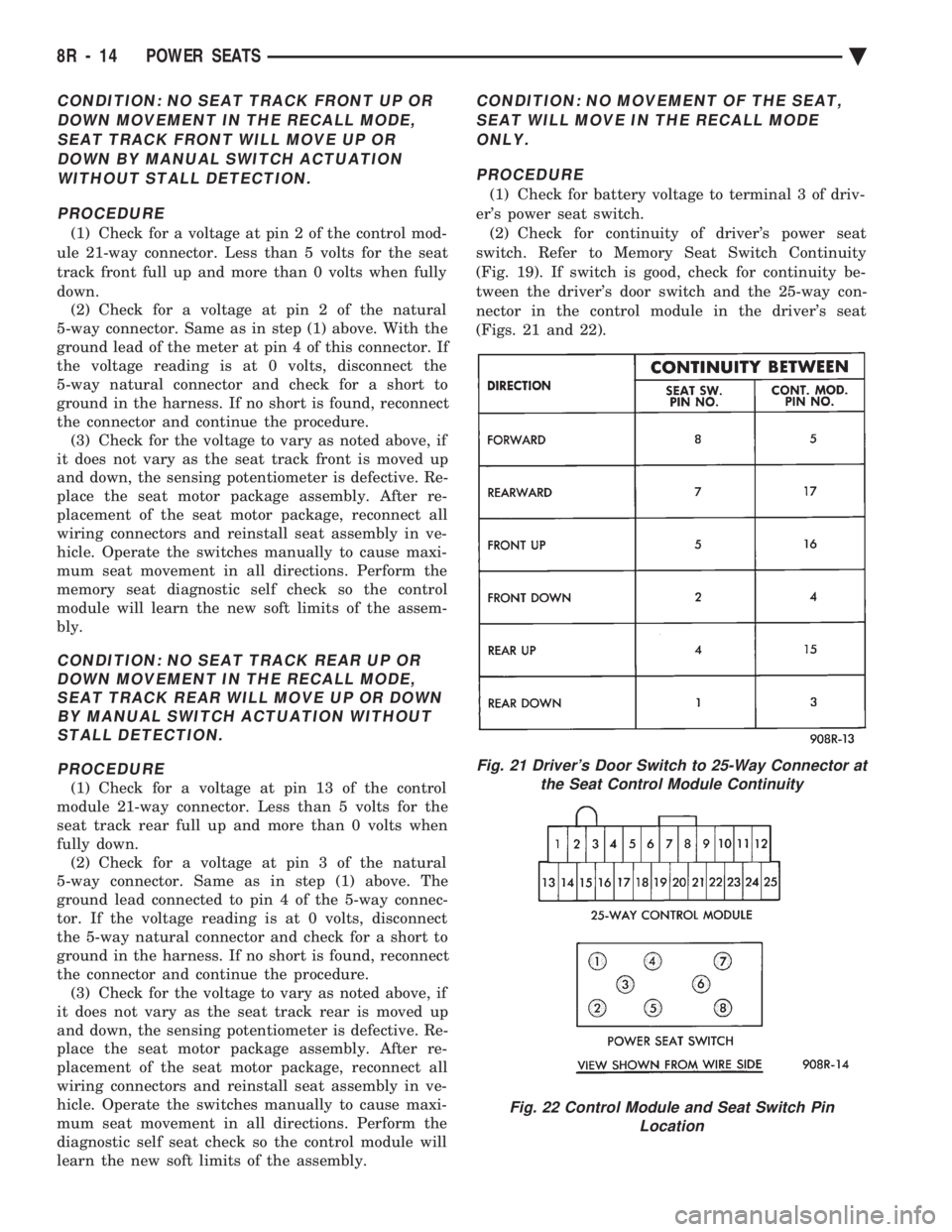
switch. Refer to Memory Seat Switch Continuity
(Fig. 19). If switch is good, check for continuity be-
tween the driver's door switch and the 25-way con-
nector in the control module in the driver's seat
(Figs. 21 and 22).
Fig. 21 Driver's Door Switch to 25-Way Connector at the Seat Control Module Continuity
Fig. 22 Control Module and Seat Switch Pin Location
8R - 14 POWER SEATS Ä
Page 727 of 2438
POWER WINDOWS
CONTENTS
page page
BENCH REPAIR OF REGULATOR AND MOTOR CONVENTIONAL REGULATORS .......... 5
GEAR AND PINION REPLACEMENT AND LUBRICATION ....................... 3
GENERAL INFORMATION .................. 1
MOTOR REPLACEMENT ................... 7
MOTOR REPLACEMENT CONVENTIONAL REGULATORS ....................... 3
MOTOR REPLACEMENTÐFLEX DRIVE REGULATORS ......................... 5 POWER WINDOW CABLE HOUSING/MOTOR RE-
PLACEMENTÐAC and AY BODIES ........ 7
QUARTER WINDOW MOTOR REPLACEMENTÐ AJ BODY ............................. 9
QUARTER WINDOW REPLACEMENTÐ AJ BODY ............................. 8
WINDOW LIFT MOTOR TEST .............. 1
WINDOW LIFT SWITCH TEST .............. 1
WIRING VOLTAGE TEST .................. 1
GENERAL INFORMATION
Front and rear door window lift motors are of the
permanent magnet type. A positive and negative bat-
tery connection to either of the two motor terminals
will cause the motor to rotate in one direction. Re-
versing current through these same two connections
will cause the motor to rotate in the opposite direc-
tion. Each individual motor is grounded through the
master switch by a black wire attached to the left
cowl panel. It is necessary that the window be free to slide up
and down in the glass channels or tubes and tracks.
If the window is not free to move up and down, the
window lift motor will not be able to move the glass. To determine if the glass is free is to disconnect the
regulator from the glass lift plate, and slide the win-
dow up and down by hand. For conventional arm-sec-
tor regulators, after the lift plate is detached from
the glass, it will slide off the regulator drive arm.
Flex-drive regulators may be detached the same way
or by removing one screw holding the flex rack to the
lift plate drive arm.
WIRING VOLTAGE TEST
The following wiring test determines whether or
not voltage is continuous through the body harness
to switch. After removing switch for testing purposes, care-
fully separate multiple terminal block on wiring har-
ness from switch body. With ignition switch ON
connect one lead of test light to black (or gray) wire
terminal and touch other test light lead to tan wire
terminal. If the test light comes on, the wiring cir-
cuit between the battery and switch is functional. If
light does not come on, check 30 amp main fuse (cir- cuit breaker) or for a broken wire. For wiring, spe-
cific connector type and location, refer to Group 8W,
Wiring Diagrams.
WINDOW LIFT SWITCH TEST
For switch testing, remove the switch from its
mounting. Using an ohmmeter, refer to Window
Switch Continuity Charts to determine if continuity
is correct. If the results are not obtained, replace the
switch. AC and AY Bodies are equipped with an Auto-
Down feature. This feature allows the operator to
lower the driver's window without having to hold the
switch in the down position. The Auto-Down feature
can be activated by pressing the down switch past
the first detent (Stop). To test the auto-down feature, operate the window
in the normal up and down mode. If the window
works correctly in the normal mode, but not in the
auto-down mode, replace the switch. To test the window switch (other than Auto-Down
mode), install a known good switch.
WINDOW LIFT MOTOR TEST
(1) Connect positive (+) lead from a test battery to
either of the two motor terminals. (2) Connect negative (-) lead from test battery to
remaining motor terminal. (3) The motor should now rotate in one direction to
either move window up or down. (a) If window happens to already be in full UP
position and motor is connected so as to rotate in
UP direction no movement will be observed. (b) Likewise, motor connected to DOWN direc-
tion rotation, no movement will be observed if win-
dow is already in full DOWN position.
Ä POWER WINDOWS 8S - 1
Page 737 of 2438
POWER MIRRORS
CONTENTS
page page
AUTOMATIC DAY/NIGHT INSIDE MIRROR .... 7
AUTOMATIC DAY/NIGHT INSIDE MIRROR WITH ULTRALIGHT HEADLAMP CONTROL ....... 7
GENERAL INFORMATION .................. 1
HEATED MIRROR ........................ 2
INSIDE MIRROR/READING LAMPS BULB/LENS REPLACEMENT ........................ 6
INSIDE MIRROR/READING LAMPS REPLACEMENT ........................ 6
MIRROR ASSEMBLY REPLACEMENTÐAA BODY.5
MIRROR ASSEMBLY REPLACEMENTÐ AC AND AY BODIES .................... 5
MIRROR ASSEMBLY REPLACEMENTÐAG BODY.5
MIRROR ASSEMBLY REPLACEMENTÐAJ BODY.5
MIRROR ASSEMBLY REPLACEMENTÐAP BODY.5
MIRROR MOTOR TEST PROCEDURE ........ 2
MIRROR SWITCH REPLACEMENTÐAA BODY . 3
MIRROR SWITCH REPLACEMENTÐAC AND AY BODIES .............................. 4
MIRROR SWITCH REPLACEMENTÐAG AND AJ BODIES .............................. 3
MIRROR SWITCH REPLACEMENTÐAP BODY . 4
MIRROR SWITCH TEST PROCEDURE ....... 2
TEST PROCEDURES ...................... 2
GENERAL INFORMATION
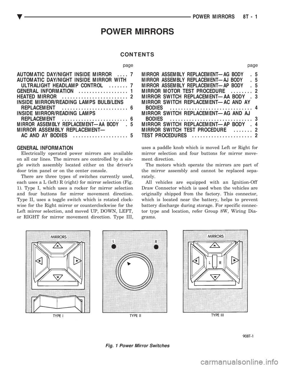
Electrically operated power mirrors are available
on all car lines. The mirrors are controlled by a sin-
gle switch assembly located either on the driver's
door trim panel or on the center console. There are three types of switches currently used,
each use s a L (left) R (right) for mirror selection (Fig.
1). Type I, which uses a rocker for mirror selection
and four buttons for mirror movement direction.
Type II, uses a toggle switch which is rotated clock-
wise for the Right mirror or counterclockwise for the
Left mirror selection, and moved UP, DOWN, LEFT,
or RIGHT for mirror movement direction. Type III, uses a paddle knob which is moved Left or Right for
mirror selection and four buttons for mirror move-
ment direction.
The motors which operate the mirrors are part of
the mirror assembly and cannot be replaced sepa-
rately. All vehicles are equipped with an Ignition-Off
Draw Connector which is used when the vehicles are
originally shipped from the factory. This connector,
which is located near the battery, helps to prevent
battery discharge during storage. For specific connec-
tor type and location, refer Group 8W, Wiring Dia-
grams.
Fig. 1 Power Mirror Switches
Ä POWER MIRRORS 8T - 1
Page 749 of 2438
CONDITION: NO TONE WHEN HEADLAMPS ARE ON AND DRIVER'S DOOR IS OPEN, ANDIGNITION IS OFF
PROCEDURE
(1) Check left door jamb switch for good ground
when driver's door is open. This may be checked at
terminal 1 of 25-way body controller connector. (2) Check for battery feed at terminal 16 of 25-way
body controller connector. (3) Check headlamp switch.
CONDITION: NO TONE WHEN KEY IS LEFT INIGNITION AND DRIVER'S DOOR IS OPEN
PROCEDURE
(1) Check left door jamb switch for good ground
when driver's door is open. This may be checked at
terminal 1 of 25-way body controller connector. (2) Check for battery feed at terminal 16 of 25-way
body controller connector. (3) Check key-in switch.
CONDITION: CHIMES CONTINUE WHENHEADLAMPS ARE TURNED OFF AND/OR KEYIS REMOVED FROM IGNITION
PROCEDURE
Check wiring for a grounded condition between
headlamp switch, key-in switch, and body controller.
SERVICE PROCEDURES
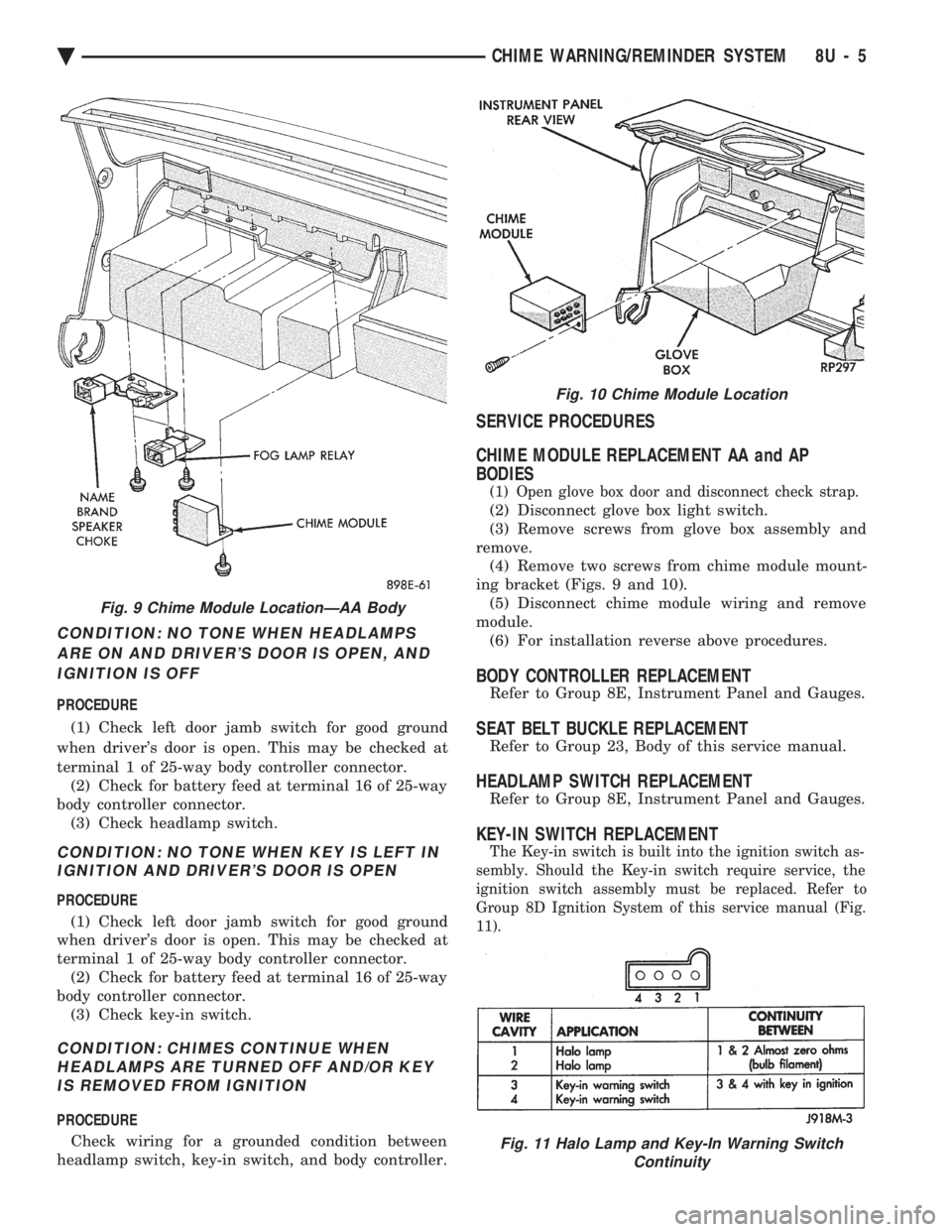
CHIME MODULE REPLACEMENT AA and AP
BODIES
(1) Open glove box door and disconnect check strap.
(2) Disconnect glove box light switch.
(3) Remove screws from glove box assembly and
remove. (4) Remove two screws from chime module mount-
ing bracket (Figs. 9 and 10). (5) Disconnect chime module wiring and remove
module. (6) For installation reverse above procedures.
BODY CONTROLLER REPLACEMENT
Refer to Group 8E, Instrument Panel and Gauges.
SEAT BELT BUCKLE REPLACEMENT
Refer to Group 23, Body of this service manual.
HEADLAMP SWITCH REPLACEMENT
Refer to Group 8E, Instrument Panel and Gauges.
KEY-IN SWITCH REPLACEMENT
The Key-in switch is built into the ignition switch as-
sembly. Should the Key-in switch require service, the
ignition switch assembly must be replaced. Refer to
Group 8D Ignition System of this service manual (Fig.
11).
Fig. 9 Chime Module LocationÐAA Body
Fig. 10 Chime Module Location
Fig. 11 Halo Lamp and Key-In Warning Switch Continuity
Ä CHIME WARNING/REMINDER SYSTEM 8U - 5
Page 1592 of 2438
valve spring retainer locks to become dislocated
when depressing the valve spring. Check and make
sure the locks are in their proper location. (3) Install valve cover as previously outlined in
this section.
VALVE SPRINGS AND VALVE STEM SEALS
REMOVAL
(1) Remove rocker arms as previously outlined in
this section. (2) Rotate crankshaft until piston is at TDC on
compression. (3) With air hose attached to adapter tool installed
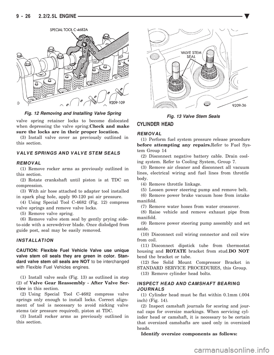
in spark plug hole, apply 90-120 psi air pressure. (4) Using Special Tool C-4682 (Fig. 12) compress
valve springs and remove valve locks. (5) Remove valve spring.
(6) Remove valve stem seal by gently prying side-
to-side with a screwdriver blade. Once dislodged from
guide post, seal may be easily removed.
INSTALLATION
CAUTION: Flexible Fuel Vehicle Valve use unique
valve stem oil seals they are green in color. Stan-
dard valve stem oil seals are NOT to be interchanged
with Flexible Fuel Vehicles engines.
(1) Install valve seals (Fig. 13) as outlined in step
(2) of Valve Gear Reassembly - After Valve Ser-
vice in this section.
(2) Using Special Tool C-4682 compress valve
springs only enough to install locks. Correct align-
ment of tool is necessary to avoid nicking valve
stems (air pressure required), piston at TDC. (3) Install rocker arms as previously outlined in
this section.
CYLINDER HEAD
REMOVAL
(1) Perform fuel system pressure release procedure
before attempting any repairs. Refer to Fuel Sys-
tem Group 14 (2) Disconnect negative battery cable. Drain cool-
ing system. Refer to Cooling System, Group 7. (3) Remove air cleaner and disconnect all vacuum
lines, electrical wiring and fuel lines from throttle
body. (4) Remove throttle linkage.
(5) Loosen power steering pump and remove belt.
(6) Remove power brake vacuum hose from intake
manifold. (7) Remove water hoses from water crossover.
(8) Raise vehicle and remove exhaust pipe from
manifold. (9) Remove power steering pump assembly and set
aside. (10) Disconnect coil wiring connector and coil wire
from coil. (11) Disconnect dipstick tube from thermostat
housing and ROTATEbracket from stud. DO NOT
bend the bracket or tube. (12) See Solid Mount Compressor Bracket in
STANDARD SERVICE PROCEDURES, this Group. (13) Remove cylinder head bolts.
INSPECT HEAD AND CAMSHAFT BEARINGJOURNALS
(1) Cylinder head must be flat within 0.1mm (.004
inch) (Fig. 14). (2) Inspect camshaft journals for scoring and jour-
nal caps for oversize markings. When servicing cyl-
inder head or camshaft, it is necessary to be certain
that oversized camshafts are used only in oversized
heads. Identify oversize components as follows:
Fig. 12 Removing and Installing Valve SpringFig. 13 Valve Stem Seals
9 - 26 2.2/2.5L ENGINE Ä
Page 1635 of 2438
LEFT SIDE MOUNT
(1) Raise vehicle on hoist and remove left front
wheel. (2) Remove inter splash shield.
(3) Support the transmission with a transmission
jack. (4) Remove the insulator thru bolt from the mount.
(5) Remove the transmission mount fasteners and
remove mount. (6) Reverse removal procedure for installation. En-
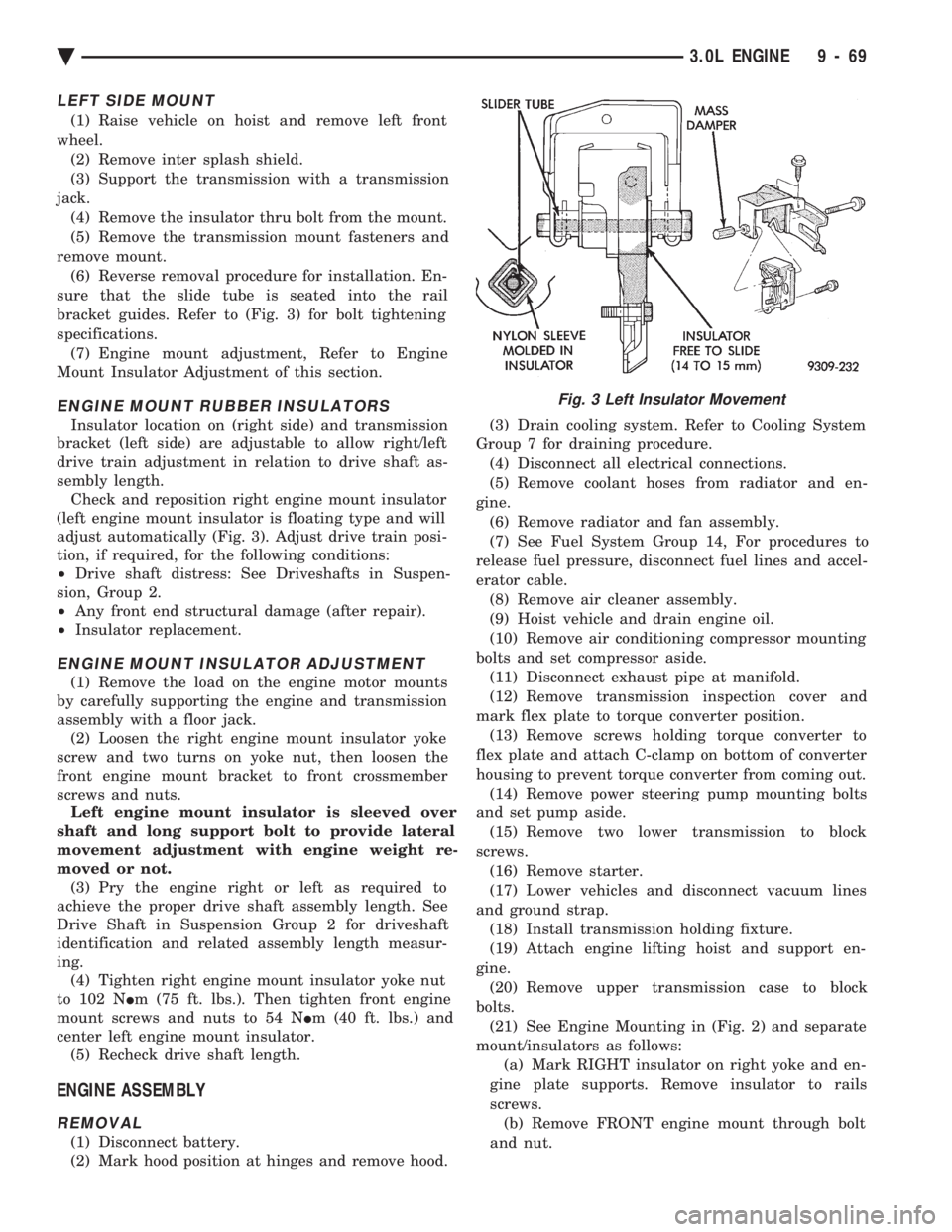
sure that the slide tube is seated into the rail
bracket guides. Refer to (Fig. 3) for bolt tightening
specifications. (7) Engine mount adjustment, Refer to Engine
Mount Insulator Adjustment of this section.
ENGINE MOUNT RUBBER INSULATORS
Insulator location on (right side) and transmission
bracket (left side) are adjustable to allow right/left
drive train adjustment in relation to drive shaft as-
sembly length. Check and reposition right engine mount insulator
(left engine mount insulator is floating type and will
adjust automatically (Fig. 3). Adjust drive train posi-
tion, if required, for the following conditions:
² Drive shaft distress: See Driveshafts in Suspen-
sion, Group 2.
² Any front end structural damage (after repair).
² Insulator replacement.
ENGINE MOUNT INSULATOR ADJUSTMENT
(1) Remove the load on the engine motor mounts
by carefully supporting the engine and transmission
assembly with a floor jack. (2) Loosen the right engine mount insulator yoke
screw and two turns on yoke nut, then loosen the
front engine mount bracket to front crossmember
screws and nuts. Left engine mount insulator is sleeved over
shaft and long support bolt to provide lateral
movement adjustment with engine weight re-
moved or not. (3) Pry the engine right or left as required to
achieve the proper drive shaft assembly length. See
Drive Shaft in Suspension Group 2 for driveshaft
identification and related assembly length measur-
ing. (4) Tighten right engine mount insulator yoke nut
to 102 N Im (75 ft. lbs.). Then tighten front engine
mount screws and nuts to 54 N Im (40 ft. lbs.) and
center left engine mount insulator. (5) Recheck drive shaft length.
ENGINE ASSEMBLY
REMOVAL
(1) Disconnect battery.
(2) Mark hood position at hinges and remove hood. (3) Drain cooling system. Refer to Cooling System
Group 7 for draining procedure. (4) Disconnect all electrical connections.
(5) Remove coolant hoses from radiator and en-
gine. (6) Remove radiator and fan assembly.
(7) See Fuel System Group 14, For procedures to
release fuel pressure, disconnect fuel lines and accel-
erator cable. (8) Remove air cleaner assembly.
(9) Hoist vehicle and drain engine oil.
(10) Remove air conditioning compressor mounting
bolts and set compressor aside. (11) Disconnect exhaust pipe at manifold.
(12) Remove transmission inspection cover and
mark flex plate to torque converter position. (13) Remove screws holding torque converter to
flex plate and attach C-clamp on bottom of converter
housing to prevent torque converter from coming out. (14) Remove power steering pump mounting bolts
and set pump aside. (15) Remove two lower transmission to block
screws. (16) Remove starter.
(17) Lower vehicles and disconnect vacuum lines
and ground strap. (18) Install transmission holding fixture.
(19) Attach engine lifting hoist and support en-
gine. (20) Remove upper transmission case to block
bolts. (21) See Engine Mounting in (Fig. 2) and separate
mount/insulators as follows: (a) Mark RIGHT insulator on right yoke and en-
gine plate supports. Remove insulator to rails
screws. (b) Remove FRONT engine mount through bolt
and nut.
Fig. 3 Left Insulator Movement
Ä 3.0L ENGINE 9 - 69
Page 1668 of 2438
(15) Install hood.
(16) Connect battery.
(17) Start engine and run until operating temper-
ature is reached. (18) Adjust transmission or linkage if necessary.
ROCKER ARMS AND SHAFT ASSEMBLY
REMOVAL
(1) Remove upper intake manifold assembly. Refer
to Intake and Exhaust Manifolds, Group 11. (2) Disconnect spark plug wires by pulling on the
boot straight out in line with plug. (3) Disconnect closed ventilation system and evap-
oration control system from cylinder head cover. (4) Remove cylinder head cover and gasket.
(5) Remove four rocker shaft bolts and retainers.
(6) Remove rocker arms and shaft assembly.
(7) If rocker arm assemblies are disassembled for
cleaning or replacement. Assemble rocker arms in
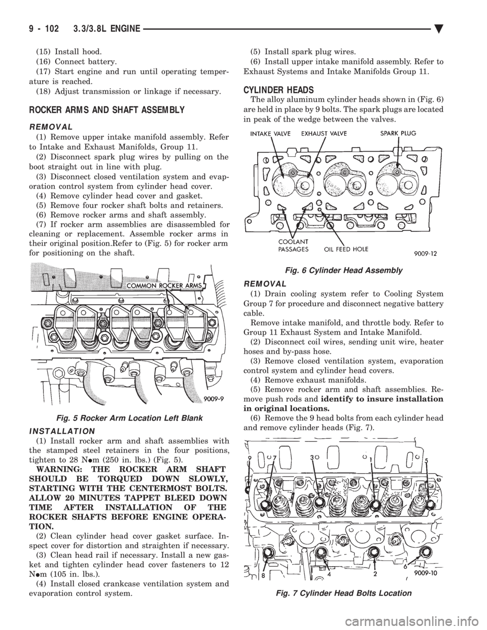
their original position.Refer to (Fig. 5) for rocker arm
for positioning on the shaft.
INSTALLATION
(1) Install rocker arm and shaft assemblies with
the stamped steel retainers in the four positions,
tighten to 28 N Im (250 in. lbs.) (Fig. 5).
WARNING: THE ROCKER ARM SHAFT
SHOULD BE TORQUED DOWN SLOWLY,
STARTING WITH THE CENTERMOST BOLTS.
ALLOW 20 MINUTES TAPPET BLEED DOWN
TIME AFTER INSTALLATION OF THE
ROCKER SHAFTS BEFORE ENGINE OPERA-
TION. (2) Clean cylinder head cover gasket surface. In-
spect cover for distortion and straighten if necessary. (3) Clean head rail if necessary. Install a new gas-
ket and tighten cylinder head cover fasteners to 12
N Im (105 in. lbs.).
(4) Install closed crankcase ventilation system and
evaporation control system. (5) Install spark plug wires.
(6) Install upper intake manifold assembly. Refer to
Exhaust Systems and Intake Manifolds Group 11.
CYLINDER HEADS
The alloy aluminum cylinder heads shown in (Fig. 6)
are held in place by 9 bolts. The spark plugs are located
in peak of the wedge between the valves.
REMOVAL
(1) Drain cooling system refer to Cooling System
Group 7 for procedure and disconnect negative battery
cable. Remove intake manifold, and throttle body. Refer to
Group 11 Exhaust System and Intake Manifold. (2) Disconnect coil wires, sending unit wire, heater
hoses and by-pass hose. (3) Remove closed ventilation system, evaporation
control system and cylinder head covers. (4) Remove exhaust manifolds.
(5) Remove rocker arm and shaft assemblies. Re-
move push rods and identify to insure installation
in original locations. (6) Remove the 9 head bolts from each cylinder head
and remove cylinder heads (Fig. 7).
Fig. 5 Rocker Arm Location Left Blank
Fig. 6 Cylinder Head Assembly
Fig. 7 Cylinder Head Bolts Location
9 - 102 3.3/3.8L ENGINE Ä
Page 1756 of 2438
jector terminal in the harness connector. Repeat pro-
cedure for 2 to 3 injectors.
FUEL TANK
DRAINING FUEL TANK
WARNING: RELEASE FUEL SYSTEM PRESSURE
BEFORE SERVICING FUEL SYSTEM COMPONENTS.
WHEN SERVICING FLEXIBLE FUEL VEHICLES,
WEAR METHANOL RESISTANT GLOVES AND EYE
PROTECTION AND AVOID BREATHING FUMES. DO
NOT ALLOW METHANOL/GASOLINE MIXTURES TO
CONTACT SKIN. SERVICE VEHICLES IN WELL VEN-
TILATED AREAS AND AVOID IGNITION SOURCES.
NEVER SMOKE WHILE SERVICING THE VEHICLE.
(1) Remove fuel filler cap.
(2) Perform the Fuel System Pressure Release pro-
cedure. (3) Remove ground cable from battery.
(4) Raise vehicle on hoist.
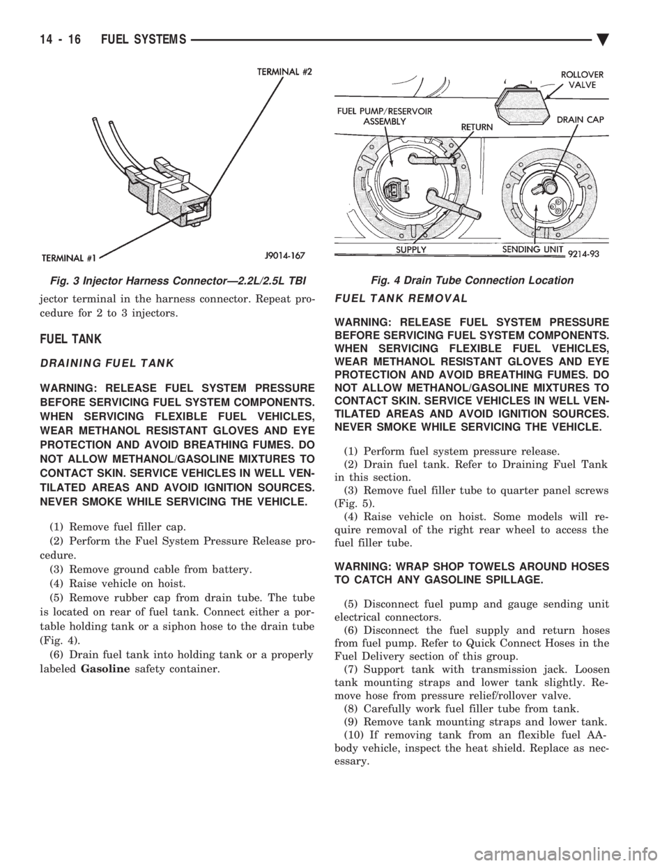
(5) Remove rubber cap from drain tube. The tube
is located on rear of fuel tank. Connect either a por-
table holding tank or a siphon hose to the drain tube
(Fig. 4). (6) Drain fuel tank into holding tank or a properly
labeled Gasoline safety container.
FUEL TANK REMOVAL
WARNING: RELEASE FUEL SYSTEM PRESSURE
BEFORE SERVICING FUEL SYSTEM COMPONENTS.
WHEN SERVICING FLEXIBLE FUEL VEHICLES,
WEAR METHANOL RESISTANT GLOVES AND EYE
PROTECTION AND AVOID BREATHING FUMES. DO
NOT ALLOW METHANOL/GASOLINE MIXTURES TO
CONTACT SKIN. SERVICE VEHICLES IN WELL VEN-
TILATED AREAS AND AVOID IGNITION SOURCES.
NEVER SMOKE WHILE SERVICING THE VEHICLE.
(1) Perform fuel system pressure release.
(2) Drain fuel tank. Refer to Draining Fuel Tank
in this section. (3) Remove fuel filler tube to quarter panel screws
(Fig. 5). (4) Raise vehicle on hoist. Some models will re-
quire removal of the right rear wheel to access the
fuel filler tube.
WARNING: WRAP SHOP TOWELS AROUND HOSES
TO CATCH ANY GASOLINE SPILLAGE.
(5) Disconnect fuel pump and gauge sending unit
electrical connectors. (6) Disconnect the fuel supply and return hoses
from fuel pump. Refer to Quick Connect Hoses in the
Fuel Delivery section of this group. (7) Support tank with transmission jack. Loosen
tank mounting straps and lower tank slightly. Re-
move hose from pressure relief/rollover valve. (8) Carefully work fuel filler tube from tank.
(9) Remove tank mounting straps and lower tank.
(10) If removing tank from an flexible fuel AA-
body vehicle, inspect the heat shield. Replace as nec-
essary.
Fig. 3 Injector Harness ConnectorÐ2.2L/2.5L TBIFig. 4 Drain Tube Connection Location
14 - 16 FUEL SYSTEMS Ä