battery location CHEVROLET DYNASTY 1993 Workshop Manual
[x] Cancel search | Manufacturer: CHEVROLET, Model Year: 1993, Model line: DYNASTY, Model: CHEVROLET DYNASTY 1993Pages: 2438, PDF Size: 74.98 MB
Page 2221 of 2438
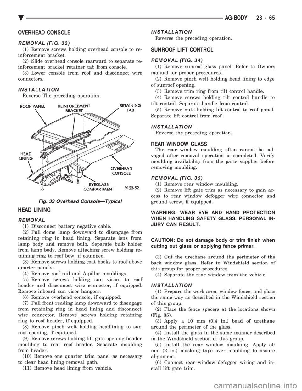
OVERHEAD CONSOLE
REMOVAL (FIG. 33)
(1) Remove screws holding overhead console to re-
inforcement bracket. (2) Slide overhead console rearward to separate re-
inforcement bracket retainer tab from console. (3) Lower console from roof and disconnect wire
connectors.
INSTALLATION
Reverse The preceding operation.
HEAD LINING
REMOVAL
(1) Disconnect battery negative cable.
(2) Pull dome lamp downward to disengage from
retaining ring in head lining. Separate lens from
lamp body and remove bulb. Separate bulb holder
from lamp body. Remove attaching screw holding re-
taining ring to roof bow, if equipped. (3) Remove screws holding coat hooks to roof above
quarter panels. (4) Remove roof rail and A-pillar mouldings.
(5) Remove screws holding sun visors to roof
header and disconnect wire connector, if equipped.
Remove inboard sun visor hangers. (6) Remove overhead console, if equipped.
(7) Pull front reading lamp downward to disengage
from retaining ring in head lining and disconnect
wire connector. Remove screws holding retaining
ring to roof header, if equipped. (8) Remove pinch welt holding headlining to sun
roof opening, if equipped. (9) Remove screws holding lift gate opening header
moulding to rear roof header. Separate moulding
from header. (10) Remove one quarter trim panel as necessary
to clear head lining removal path. (11) Remove head lining from vehicle.
INSTALLATION
Reverse the preceding operation.
SUNROOF LIFT CONTROL
REMOVAL (FIG. 34)
(1) Remove sunroof glass panel. Refer to Owners
manual for proper procedures. (2) Remove pinch welt holding head lining to edge
of sunroof opening. (3) Remove trim ring from tilt control handle.
(4) Remove screws holding tilt control handle to
tilt control. Separate handle from control. (5) Remove nuts holding lift control to roof panel.
Separate lift control from roof.
INSTALLATION
Reverse the preceding operation.
REAR WINDOW GLASS
The rear window moulding often cannot be sal-
vaged after removal operation is completed. Verify
moulding availability from the parts supplier before
removing moulding.
REMOVAL (FIG. 35)
(1) Remove rear window moulding.
(2) Remove lift gate trim as necessary to gain ac-
cess to rear window defogger wire connector and
ground screw, if equipped.
WARNING: WEAR EYE AND HAND PROTECTION
WHEN HANDLING SAFETY GLASS. PERSONAL IN-
JURY CAN RESULT.
CAUTION: Do not damage body or trim finish when
cutting out glass or applying fence primer.
(3) Cut the urethane around the perimeter of the
back window glass. Refer to Windshield section of
this group for proper procedures. (4) Separate the rear window from the vehicle.
INSTALLATION
(1) Prepare the work area, window fence, and glass
the same way as described in the Windshield section
of this group. (2) Place the fence spacers at the locations shown
(Fig. 35). (3) Apply a 10 mm (0.4 in.) bead of urethane
around the perimeter of the glass. (4) Install the glass in the same manner described
in the Windshield section of this group. (5) Install the rear window moulding. Apply 50
mm (2 in.) masking tape over moulding to assure
alignment. (6) Connect rear window defogger wiring and in-
stall lift gate trim.
Fig. 33 Overhead ConsoleÐTypical
Ä AG-BODY 23 - 65
Page 2237 of 2438
HEAD LINING
REMOVAL
(1) Disconnect battery negative cable.
(2) Pull dome lamp downward to disengage from
retaining ring in head lining. Separate lens from
lamp body and remove bulb. Separate bulb holder
from lamp body. Remove attaching screw holding re-
taining ring to roof bow, if equipped. (3) Remove screws holding coat hooks to roof above
quarter panels. (4) Remove roof rail and A-pillar mouldings.
(5) Remove screws holding sun visors to roof
header and disconnect wire connector, if equipped.
Remove inboard sun visor hangers. (6) Remove overhead console, if equipped.
(7) Pull front reading lamp downward to disengage
from retaining ring in head lining and disconnect
wire connector. Remove screws holding retaining
ring to roof header, if equipped. (8) Remove pinch welt holding headlining to sun
roof opening, if equipped. (9) Remove one quarter trim panel as necessary to
clear head lining removal path. (10) Disengage hook and loop fasteners holding
head lining to roof above rear window and slide head
lining from behind quarter panel. (11) Remove head lining from vehicle.
INSTALLATION
Reverse the preceding operation.
SUN ROOF WEATHERSTRIP
REMOVAL (FIG. 22)
(1) Remove sun roof sunshade and glass. Refer to
Owner's Manual for instructions. (2) Pull weatherstrip from pinch flange around sun
roof opening.
INSTALLATION
Reverse the preceding operation.
SUN ROOF AIR DEFLECTOR
REMOVAL (FIG. 22)
(1) Remove sun roof sunshade and glass. Refer to
Owner's Manual for instructions. (2) Disengage snap-on linkage at rear of air deflec-
tor in sun roof opening. (3) Remove screws holding air deflector to front of
sun roof opening.
INSTALLATION
Reverse the preceding operation.
SUN ROOF DRAIN TUBES
REMOVAL (FIG. 22)
(1) Remove head lining as necessary.
(2) Remove A-pillar or quarter trim covers as nec-
essary. (3) Remove cowl panel and sill plate trim as neces-
sary. (4) Disconnect effected drain tube from nipple at
sun roof opening. (5) Pull drain tube upward to remove from pillar
involved.
INSTALLATION
Reverse the preceding operation. Route the tube to
avoid kinks or puncture from sharp edges.
REAR WINDOW GLASS
REMOVAL (FIG. 23)
(1) Remove rear window mouldings.
(2) Remove interior trim as necessary to gain ac-
cess to rear window defogger wire connector and
ground screw, if equipped.
WARNING: WEAR EYE AND HAND PROTECTION
WHEN HANDLING SAFETY GLASS. PERSONAL IN-
JURY CAN RESULT.
CAUTION: Do not damage body or trim finish when
cutting out glass or applying fence primer.
(3) Cut the urethane around the perimeter of the
back window glass. Refer to Windshield section of
this group for proper procedures. (4) Separate the rear window from the vehicle.
INSTALLATION
(1) Prepare the work area, window fence, and glass
the same way as described in the Windshield section
of this group. (2) Place fence spacers at the locations shown (Fig.
23). (3) Apply a 10 mm (0.4 in.) bead of urethane
around the perimeter of the glass. (4) Install the glass in the same manner described
in the Windshield section of this group. (5) Install the rear window moulding.
(6) Connect rear window defogger wiring and in-
stall interior trim. (7) After urethane has cured, water test rear win-
dow to verify repair. Verify rear window defogger op-
eration, see Group 8N, Rear Window Defogger.
Ä AJ-BODY 23 - 81
Page 2254 of 2438
ing hood, align all marks and secure bolts. The hood
should be aligned to 4 mm (0.160 in.) gap to the front
fenders and flush across the top surfaces along fend-
ers.(4) Remove the top hood to hinge attaching bolts
and loosen the bottom bolts until they can be re-
moved by hand. (5) With assistance of a helper at the opposite side
of the vehicle to support the hood, remove the bottom
hood to hinge attaching bolts. Separate the hood
from the vehicle.
HOOD INSTALLATION
Reverse the preceding operation.
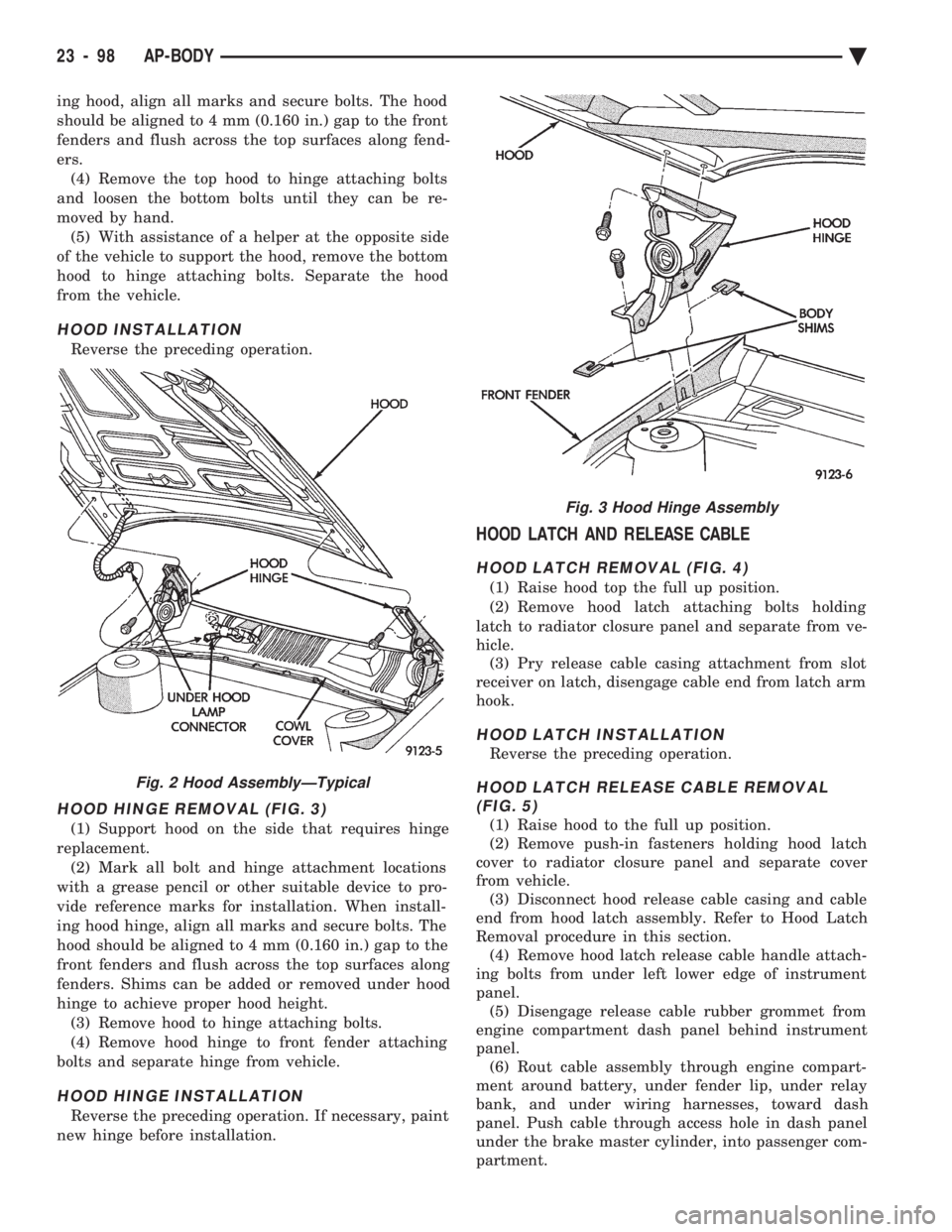
HOOD HINGE REMOVAL (FIG. 3)
(1) Support hood on the side that requires hinge
replacement. (2) Mark all bolt and hinge attachment locations
with a grease pencil or other suitable device to pro-
vide reference marks for installation. When install-
ing hood hinge, align all marks and secure bolts. The
hood should be aligned to 4 mm (0.160 in.) gap to the
front fenders and flush across the top surfaces along
fenders. Shims can be added or removed under hood
hinge to achieve proper hood height. (3) Remove hood to hinge attaching bolts.
(4) Remove hood hinge to front fender attaching
bolts and separate hinge from vehicle.
HOOD HINGE INSTALLATION
Reverse the preceding operation. If necessary, paint
new hinge before installation.
HOOD LATCH AND RELEASE CABLE
HOOD LATCH REMOVAL (FIG. 4)
(1) Raise hood top the full up position.
(2) Remove hood latch attaching bolts holding
latch to radiator closure panel and separate from ve-
hicle. (3) Pry release cable casing attachment from slot
receiver on latch, disengage cable end from latch arm
hook.
HOOD LATCH INSTALLATION
Reverse the preceding operation.
HOOD LATCH RELEASE CABLE REMOVAL (FIG. 5)
(1) Raise hood to the full up position.
(2) Remove push-in fasteners holding hood latch
cover to radiator closure panel and separate cover
from vehicle. (3) Disconnect hood release cable casing and cable
end from hood latch assembly. Refer to Hood Latch
Removal procedure in this section. (4) Remove hood latch release cable handle attach-
ing bolts from under left lower edge of instrument
panel. (5) Disengage release cable rubber grommet from
engine compartment dash panel behind instrument
panel. (6) Rout cable assembly through engine compart-
ment around battery, under fender lip, under relay
bank, and under wiring harnesses, toward dash
panel. Push cable through access hole in dash panel
under the brake master cylinder, into passenger com-
partment.
Fig. 2 Hood AssemblyÐTypical
Fig. 3 Hood Hinge Assembly
23 - 98 AP-BODY Ä
Page 2317 of 2438
VARIABLE DISPLACEMENT COMPRESSORÐMODEL 6C17 INDEX
page page
Clutch Coil Tests ......................... 17
Compressor ............................. 17
Compressor Clutch Inoperative .............. 13
Compressor Clutch/Coil Assembly ............ 19
Compressor Diagnosis ..................... 13
Compressor Front Shaft Seal ............... 20 Compressor High Pressure Cut-Out Switch
..... 21
Compressor High Pressure Relief Valve (HPR) . . 22
Compressor Identification ................... 13
Compressor Main or Sub Control Valves ....... 22
Compressor Noise ........................ 13
General Information ....................... 13
GENERAL INFORMATION
The Variable Displacement Compressor (VDC) pro-
vides maximum A/C performance under most condi-
tions. It is designed to operate continuously without
any cycling of the compressor clutch. The compressor
has a variable angle wobble plate with six axially
oriented cylinders. During vehicle A/C system operation, the compres-
sor will change its displacement to match the vehi-
cles A/C cooling demands. When the A/C system
needs more cooling capacity, the compressor will in-
crease its pumping capacity. This is done by increas-
ing the wobble plate angle to increase the piston
stroke. When the A/C system cooling demand is low,
the compressor will decrease its pumping capacity by
reducing the piston pumping stroke. The low cooling
capacity will prevent evaporator from freezing.
COMPRESSOR IDENTIFICATION
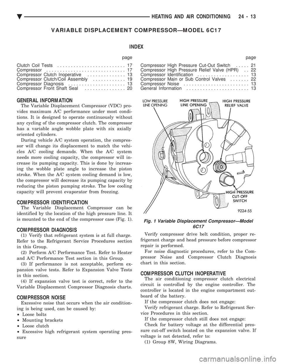
The Variable Displacement Compressor can be
identified by the location of the high pressure line. It
is mounted to the end of the compressor case (Fig. 1).
COMPRESSOR DIAGNOSIS
(1) Verify that refrigerant system is at full charge.
Refer to the Refrigerant Service Procedures section
in this Group. (2) Perform A/C Performance Test. Refer to Heater
and A/C Performance Test section in this Group. (3) If performance is not acceptable, perform ex-
pansion valve tests. Refer to Expansion Valve Tests
in this section. (4) If expansion valve test is correct, refer to the
Variable Displacement Compressor Diagnosis charts.
COMPRESSOR NOISE
Excessive noise that occurs when the air condition-
ing is being used, can be caused by:
² Loose bolts
² Mounting brackets
² Loose clutch
² Excessive high refrigerant system operating pres-
sure Verify compressor drive belt condition, proper re-
frigerant charge and head pressure before compressor
repair is performed. For noise diagnostic procedures, refer to the Com-
pressor Noise and Compressor Clutch Diagnosis
chart in this section.
COMPRESSOR CLUTCH INOPERATIVE
The air conditioning compressor clutch electrical
circuit is controlled by the engine controller. The
controller is located in the engine compartment out-
board of the battery. If the compressor clutch does not engage:
Verify refrigerant charge. Refer to Refrigerant Ser-
vice Procedures in this section. If the compressor clutch still does not engage:
Check for battery voltage at the differential pres-
sure cut-off switch located on the expansion valve. If
voltage is not detected, refer to: (1) Group 8W, Wiring Diagrams.
Fig. 1 Variable Displacement CompressorÐModel 6C17
Ä HEATING AND AIR CONDITIONING 24 - 13
Page 2362 of 2438
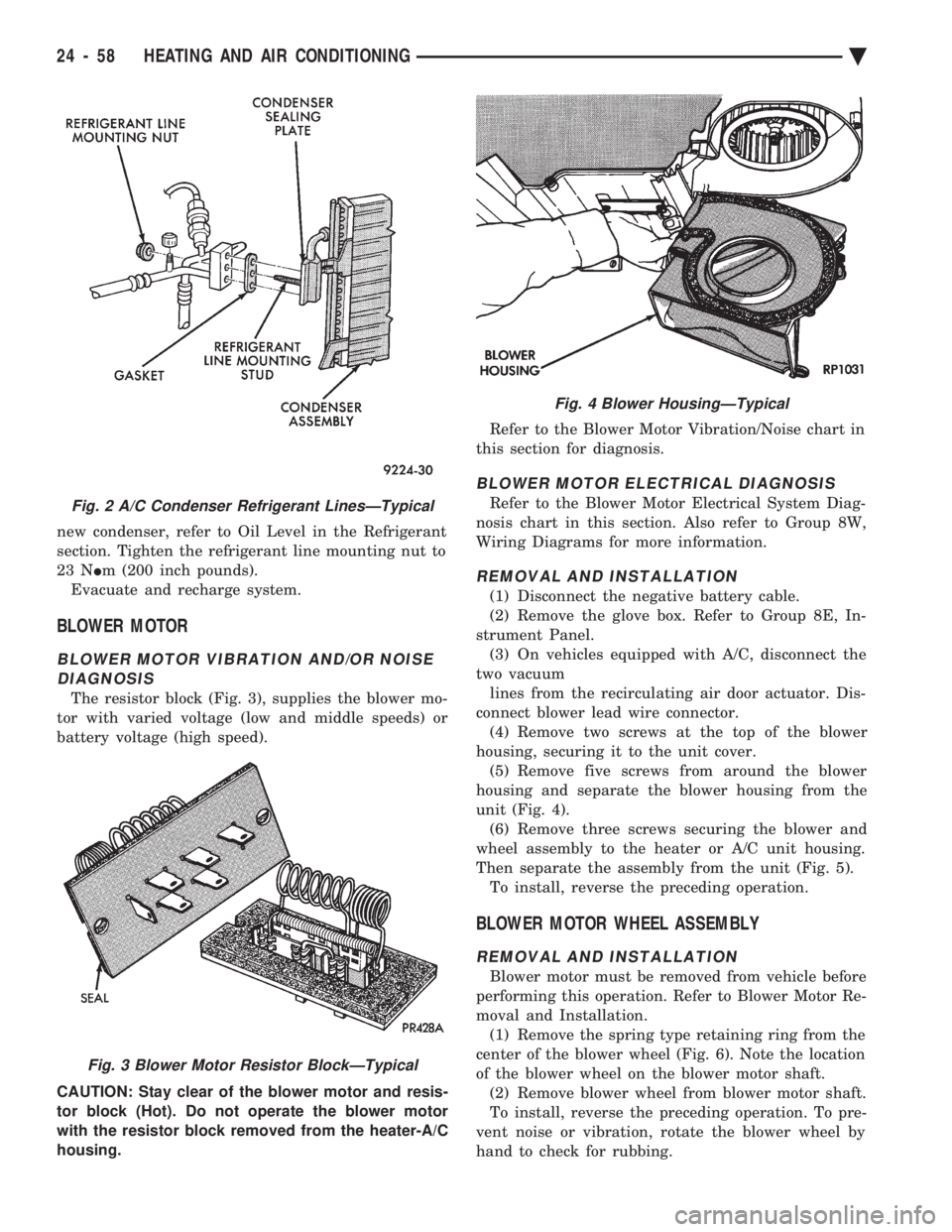
new condenser, refer to Oil Level in the Refrigerant
section. Tighten the refrigerant line mounting nut to
23 N Im (200 inch pounds).
Evacuate and recharge system.
BLOWER MOTOR
BLOWER MOTOR VIBRATION AND/OR NOISE DIAGNOSIS
The resistor block (Fig. 3), supplies the blower mo-
tor with varied voltage (low and middle speeds) or
battery voltage (high speed).
CAUTION: Stay clear of the blower motor and resis-
tor block (Hot). Do not operate the blower motor
with the resistor block removed from the heater-A/C
housing. Refer to the Blower Motor Vibration/Noise chart in
this section for diagnosis.
BLOWER MOTOR ELECTRICAL DIAGNOSIS
Refer to the Blower Motor Electrical System Diag-
nosis chart in this section. Also refer to Group 8W,
Wiring Diagrams for more information.
REMOVAL AND INSTALLATION
(1) Disconnect the negative battery cable.
(2) Remove the glove box. Refer to Group 8E, In-
strument Panel. (3) On vehicles equipped with A/C, disconnect the
two vacuum lines from the recirculating air door actuator. Dis-
connect blower lead wire connector. (4) Remove two screws at the top of the blower
housing, securing it to the unit cover. (5) Remove five screws from around the blower
housing and separate the blower housing from the
unit (Fig. 4). (6) Remove three screws securing the blower and
wheel assembly to the heater or A/C unit housing.
Then separate the assembly from the unit (Fig. 5). To install, reverse the preceding operation.
BLOWER MOTOR WHEEL ASSEMBLY
REMOVAL AND INSTALLATION
Blower motor must be removed from vehicle before
performing this operation. Refer to Blower Motor Re-
moval and Installation. (1) Remove the spring type retaining ring from the
center of the blower wheel (Fig. 6). Note the location
of the blower wheel on the blower motor shaft. (2) Remove blower wheel from blower motor shaft.
To install, reverse the preceding operation. To pre-
vent noise or vibration, rotate the blower wheel by
hand to check for rubbing.
Fig. 2 A/C Condenser Refrigerant LinesÐTypical
Fig. 3 Blower Motor Resistor BlockÐTypical
Fig. 4 Blower HousingÐTypical
24 - 58 HEATING AND AIR CONDITIONING Ä