change time CHEVROLET DYNASTY 1993 Service Manual
[x] Cancel search | Manufacturer: CHEVROLET, Model Year: 1993, Model line: DYNASTY, Model: CHEVROLET DYNASTY 1993Pages: 2438, PDF Size: 74.98 MB
Page 17 of 2438
FOREWORD
The information contained in this service manual has been prepared for the professional automotive
technician involved in daily repair operations. This manual does not cover theory of operation, which is addressed
in service training material. Information describing the operation and use of standard and optional equipment is
included in the Owner's Manual provided with the vehicle.
Information in this manual is divided into groups. These groups contain general information, diagnosis,
testing, adjustments, removal, installation, disassembly, and assembly procedures for the components.
The Component and System Index of this manual identifies the correct group for the component or system to
be serviced. To assist in locating a group title page, use the Group Tab Locator on the following page. The solid bar
after the group title is aligned to a solid tab on the first page of each group. The first page of the group has a
contents section that lists major topics within the group.
A Service Manual Comment form is included at the rear of this manual. Use the form to provide Chrysler
Corporation with your comments and suggestions.
Tightening torques are provided as a specific value throughout this manual. This value represents the
midpoint of the acceptable engineering torque range for a given fastener application. These torque values are
intended for use in service assembly and installation procedures using the correct OEM fasteners. When replacing
fasteners, always use the same type (part number) fastener as removed.
Chrysler Corporation reserves the right to change testing procedures, specifications, diagnosis, repair
methods, or vehicle wiring at any time without prior notice or incurring obligation.
NOTE: The acronyms, terminology and nomenclature used to identify emissions related components in this
manual may have changed from prior publications. These new terms are in compliance with S.A.E.
recommended practice J1930. This terminology standard (J1930) is required to comply with the 1993
California Air Research Board (CARB) requirements.
FOR INFORMATION NOT CONTAINED IN THIS MANUAL, REFER TO FRONT WHEEL DRIVE
PASSENGER VEHICLES ELECTRICALÐFUELÐEMISSIONS OR WIRING DIAGRAMS SERVICE
MANUALS.
NEXT PAGE©
Page 21 of 2438
FOREWORD
The information contained in this service manual has been prepared for the professional automotive
technician involved in daily repair operations. This manual does not cover theory of operation, which is addressed
in service training material. Information describing the operation and use of standard and optional equipment is
included in the Owner's Manual provided with the vehicle.
Information in this manual is divided into groups. These groups contain general information, diagnosis,
testing, adjustments, removal, installation, disassembly, and assembly procedures for the components.
The Component and System Index of this manual identifies the correct group for the component or system to
be serviced. To assist in locating a group title page, use the Group Tab Locator on the following page. The solid bar
after the group title is aligned to a solid tab on the first page of each group. The first page of the group has a
contents section that lists major topics within the group.
A Service Manual Comment form is included at the rear of this manual. Use the form to provide Chrysler
Corporation with your comments and suggestions.
Tightening torques are provided as a specific value throughout this manual. This value represents the
midpoint of the acceptable engineering torque range for a given fastener application. These torque values are
intended for use in service assembly and installation procedures using the correct OEM fasteners. When replacing
fasteners, always use the same type (part number) fastener as removed.
Chrysler Corporation reserves the right to change testing procedures, specifications, diagnosis, repair
methods, or vehicle wiring at any time without prior notice or incurring obligation.
NOTE: The acronyms, terminology and nomenclature used to identify emissions related components in this
manual may have changed from prior publications. These new terms are in compliance with S.A.E.
recommended practice J1930. This terminology standard (J1930) is required to comply with the 1993
California Air Research Board (CARB) requirements.
FOR INFORMATION NOT CONTAINED IN THIS MANUAL, REFER TO FRONT WHEEL DRIVE
PASSENGER VEHICLES ENGINEÐCHASSISÐBODY OR WIRING DIAGRAMS SERVICE MANUALS.
NEXT PAGE ©
Page 25 of 2438
FOREWORD
The information contained in this service manual has been prepared for the professional automotive
technician involved in daily repair operations. This manual does not cover theory of operation, which is addressed
in service training material. Information describing the operation and use of standard and optional equipment is
included in the Owner's Manual provided with the vehicle.
Information in this manual is divided into groups. These groups contain general information, diagnosis,
testing, adjustments, removal, installation, disassembly, and assembly procedures for the components.
The Component and System Index of this manual identifies the correct group for the component or system to
be serviced. To assist in locating a group title page, use the Group Tab Locator on the following page. The solid bar
after the group title is aligned to a solid tab on the first page of each group. The first page of the group has a
contents section that lists major topics within the group.
A Service Manual Comment form is included at the rear of this manual. Use the form to provide Chrysler
Corporation with your comments and suggestions.
Tightening torques are provided as a specific value throughout this manual. This value represents the
midpoint of the acceptable engineering torque range for a given fastener application. These torque values are
intended for use in service assembly and installation procedures using the correct OEM fasteners. When replacing
fasteners, always use the same type (part number) fastener as removed.
Chrysler Corporation reserves the right to change testing procedures, specifications, diagnosis, repair
methods, or vehicle wiring at any time without prior notice or incurring obligation.
NOTE: The acronyms, terminology and nomenclature used to identify emissions related components in this
manual may have changed from prior publications. These new terms are in compliance with S.A.E.
recommended practice J1930. This terminology standard (J1930) is required to comply with the
California Air Research Board (CARB) requirements.
NEXT PAGE ©
Page 29 of 2438
FOREWORD
The information contained in this Service Manual has been prepared for the professional automotive
technician involved in daily repair operations. Information describing the operation and use of standard and
optional equipment is included in the Owner's Manual provided with the vehicle.
These diagrams contain the latest information at the time of publication and incorporate the wiring schematic
for the basic vehicle and available optional equipment.
The diagrams are grouped by body type and sales division. The body codes are explained in the General
Information section. (ExampleÐAP-D, P=Shadow, Sundance). To locate a system or component refer to the black
index tabs on the next page. The tab will assist you in locating the desired area of the manual.
An alphabetical index is provided at the beginning of each section to help you in locating a system or
component. All diagrams are identified by SHEET NUMBER which is found in the lower right- or left-hand corner
of the page.
A Service Manual Comment form is included at the rear of this manual. Use the form to provide Chrysler
Corporation with your comments and suggestions.
Chrysler Corporation reserves the right to change testing procedures, specifications, diagnosis, repair
methods, or vehicle wiring at any time without prior notice or incurring obligation.
NOTE: The acronyms, terminology and nomenclature used to identify emissions related components in this
manual may have changed from prior publications. These new terms are in compliance with S.A.E.
recommended practice J1930. This terminology standard (J1930) is required to comply with the 1993
California Air Research Board (CARB) requirements.
FOR INFORMATION NOT CONTAINED IN THIS MANUAL, REFER TO THE FRONT WHEEL
DRIVE PASSENGER VEHICLES ENGINEÐCHASSISÐBODY OR ELECTRICALÐFUELÐEMISSIONS
SERVICE MANUALS.
NEXT PAGE ©
Page 45 of 2438
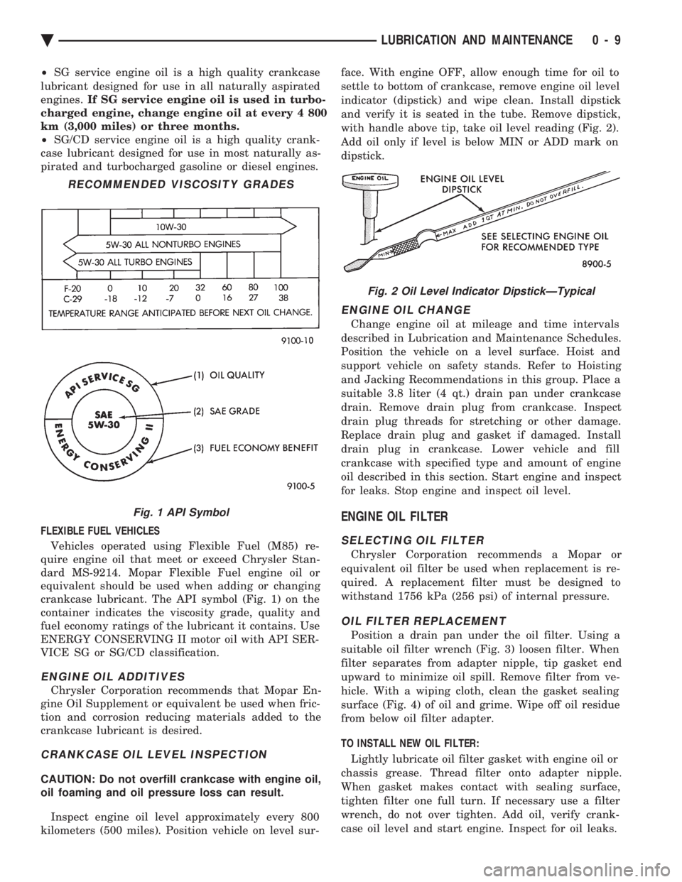
² SG service engine oil is a high quality crankcase
lubricant designed for use in all naturally aspirated
engines. If SG service engine oil is used in turbo-
charged engine, change engine oil at every 4 800
km (3,000 miles) or three months.
² SG/CD service engine oil is a high quality crank-
case lubricant designed for use in most naturally as-
pirated and turbocharged gasoline or diesel engines.
FLEXIBLE FUEL VEHICLES
Vehicles operated using Flexible Fuel (M85) re-
quire engine oil that meet or exceed Chrysler Stan-
dard MS-9214. Mopar Flexible Fuel engine oil or
equivalent should be used when adding or changing
crankcase lubricant. The API symbol (Fig. 1) on the
container indicates the viscosity grade, quality and
fuel economy ratings of the lubricant it contains. Use
ENERGY CONSERVING II motor oil with API SER-
VICE SG or SG/CD classification.
ENGINE OIL ADDITIVES
Chrysler Corporation recommends that Mopar En-
gine Oil Supplement or equivalent be used when fric-
tion and corrosion reducing materials added to the
crankcase lubricant is desired.
CRANKCASE OIL LEVEL INSPECTION
CAUTION: Do not overfill crankcase with engine oil,
oil foaming and oil pressure loss can result.
Inspect engine oil level approximately every 800
kilometers (500 miles). Position vehicle on level sur- face. With engine OFF, allow enough time for oil to
settle to bottom of crankcase, remove engine oil level
indicator (dipstick) and wipe clean. Install dipstick
and verify it is seated in the tube. Remove dipstick,
with handle above tip, take oil level reading (Fig. 2).
Add oil only if level is below MIN or ADD mark on
dipstick.
ENGINE OIL CHANGE
Change engine oil at mileage and time intervals
described in Lubrication and Maintenance Schedules.
Position the vehicle on a level surface. Hoist and
support vehicle on safety stands. Refer to Hoisting
and Jacking Recommendations in this group. Place a
suitable 3.8 liter (4 qt.) drain pan under crankcase
drain. Remove drain plug from crankcase. Inspect
drain plug threads for stretching or other damage.
Replace drain plug and gasket if damaged. Install
drain plug in crankcase. Lower vehicle and fill
crankcase with specified type and amount of engine
oil described in this section. Start engine and inspect
for leaks. Stop engine and inspect oil level.
ENGINE OIL FILTER
SELECTING OIL FILTER
Chrysler Corporation recommends a Mopar or
equivalent oil filter be used when replacement is re-
quired. A replacement filter must be designed to
withstand 1756 kPa (256 psi) of internal pressure.
OIL FILTER REPLACEMENT
Position a drain pan under the oil filter. Using a
suitable oil filter wrench (Fig. 3) loosen filter. When
filter separates from adapter nipple, tip gasket end
upward to minimize oil spill. Remove filter from ve-
hicle. With a wiping cloth, clean the gasket sealing
surface (Fig. 4) of oil and grime. Wipe off oil residue
from below oil filter adapter.
TO INSTALL NEW OIL FILTER: Lightly lubricate oil filter gasket with engine oil or
chassis grease. Thread filter onto adapter nipple.
When gasket makes contact with sealing surface,
tighten filter one full turn. If necessary use a filter
wrench, do not over tighten. Add oil, verify crank-
case oil level and start engine. Inspect for oil leaks.
RECOMMENDED VISCOSITY GRADES
Fig. 1 API Symbol
Fig. 2 Oil Level Indicator DipstickÐTypical
Ä LUBRICATION AND MAINTENANCE 0 - 9
Page 49 of 2438
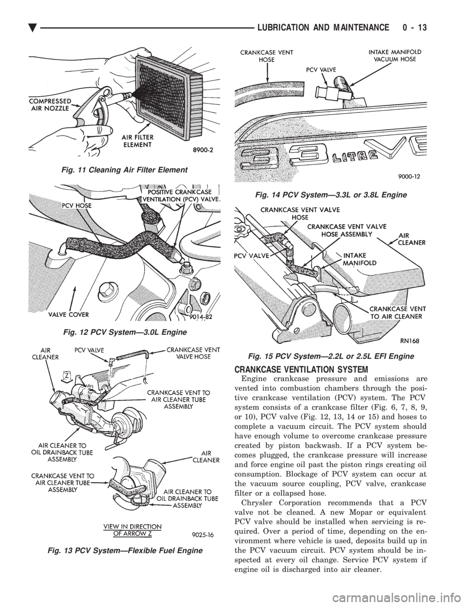
CRANKCASE VENTILATION SYSTEM
Engine crankcase pressure and emissions are
vented into combustion chambers through the posi-
tive crankcase ventilation (PCV) system. The PCV
system consists of a crankcase filter (Fig. 6, 7, 8, 9,
or 10), PCV valve (Fig. 12, 13, 14 or 15) and hoses to
complete a vacuum circuit. The PCV system should
have enough volume to overcome crankcase pressure
created by piston backwash. If a PCV system be-
comes plugged, the crankcase pressure will increase
and force engine oil past the piston rings creating oil
consumption. Blockage of PCV system can occur at
the vacuum source coupling, PCV valve, crankcase
filter or a collapsed hose. Chrysler Corporation recommends that a PCV
valve not be cleaned. A new Mopar or equivalent
PCV valve should be installed when servicing is re-
quired. Over a period of time, depending on the en-
vironment where vehicle is used, deposits build up in
the PCV vacuum circuit. PCV system should be in-
spected at every oil change. Service PCV system if
engine oil is discharged into air cleaner.
Fig. 11 Cleaning Air Filter Element
Fig. 12 PCV SystemÐ3.0L Engine
Fig. 13 PCV SystemÐFlexible Fuel Engine
Fig. 14 PCV SystemÐ3.3L or 3.8L Engine
Fig. 15 PCV SystemÐ2.2L or 2.5L EFI Engine
Ä LUBRICATION AND MAINTENANCE 0 - 13
Page 58 of 2438
BRAKE RESERVOIR LEVEL INSPECTION
WARNING: DO NOT ALLOW PETROLEUM OR WATER
BASE LIQUIDS TO CONTAMINATE BRAKE FLUID,
SEAL DAMAGE AND BRAKE FAILURE CAN RESULT.
RELIEVE PRESSURE IN ANTI-LOCK BRAKE SYS-
TEM BEFORE ADDING BRAKE FLUID TO RESER-
VOIR. IF NOT, BRAKE FLUID COULD DISCHARGED
FROM THE RESERVOIR POSSIBLY CAUSING PER-
SONAL INJURY.
The brake reservoir level should be inspected when
other under hood service is performed. It is normal
for the reservoir level to drop as disc brake pads
wear. When fluid must be added, use Mopar, Brake
Fluid or equivalent. Use only brake fluid conforming
to DOT 3, Federal, Department of Transportation
specification. To avoid brake fluid contamination, use
fluid from a properly sealed container. On vehicles with anti-lock brakes, depressurize the
system before inspecting fluid level. Turn OFF the
ignition and remove the key. Pump the brake pedal
at least 50 times to relieve the pressure in the sys-
tem.
On all vehicles, if fluid should become low after sev-
eral thousand kilometers (miles), fill the reservoir to
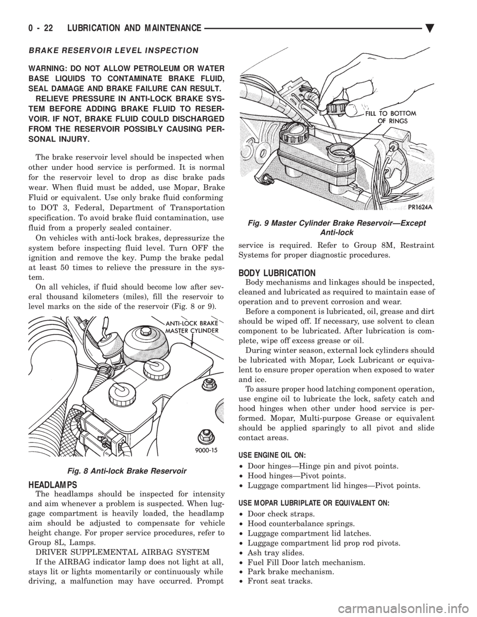
level marks on the side of the reservoir (Fig. 8 or 9).
HEADLAMPS
The headlamps should be inspected for intensity
and aim whenever a problem is suspected. When lug-
gage compartment is heavily loaded, the headlamp
aim should be adjusted to compensate for vehicle
height change. For proper service procedures, refer to
Group 8L, Lamps. DRIVER SUPPLEMENTAL AIRBAG SYSTEM
If the AIRBAG indicator lamp does not light at all,
stays lit or lights momentarily or continuously while
driving, a malfunction may have occurred. Prompt service is required. Refer to Group 8M, Restraint
Systems for proper diagnostic procedures.
BODY LUBRICATION
Body mechanisms and linkages should be inspected,
cleaned and lubricated as required to maintain ease of
operation and to prevent corrosion and wear. Before a component is lubricated, oil, grease and dirt
should be wiped off. If necessary, use solvent to clean
component to be lubricated. After lubrication is com-
plete, wipe off excess grease or oil. During winter season, external lock cylinders should
be lubricated with Mopar, Lock Lubricant or equiva-
lent to ensure proper operation when exposed to water
and ice. To assure proper hood latching component operation,
use engine oil to lubricate the lock, safety catch and
hood hinges when other under hood service is per-
formed. Mopar, Multi-purpose Grease or equivalent
should be applied sparingly to all pivot and slide
contact areas.
USE ENGINE OIL ON:
² Door hingesÐHinge pin and pivot points.
² Hood hingesÐPivot points.
² Luggage compartment lid hingesÐPivot points.
USE MOPAR LUBRIPLATE OR EQUIVALENT ON:
² Door check straps.
² Hood counterbalance springs.
² Luggage compartment lid latches.
² Luggage compartment lid prop rod pivots.
² Ash tray slides.
² Fuel Fill Door latch mechanism.
² Park brake mechanism.
² Front seat tracks.
Fig. 8 Anti-lock Brake Reservoir
Fig. 9 Master Cylinder Brake ReservoirÐExcept
Anti-lock
0 - 22 LUBRICATION AND MAINTENANCE Ä
Page 63 of 2438
FRONT SUSPENSION SERVICE PROCEDURES INDEX
page page
Ball Joints .............................. 13
Hub and Bearing Assembly ................. 20
Knuckle (Front Suspension) ................. 16
Lower Control Arm ....................... 10
Lower Control Arm Pivot Bushings ........... 11 Shock Absorbers (Strut Damper)
............. 10
Strut Damper Assembly ..................... 7
Suspension Coil Springs .................... 9
Sway Bar .............................. 14
Wheel Alignment .......................... 5
WHEEL ALIGNMENT
Front wheel alignment is the proper adjustment of
all interrelated front suspension angles. These angles
are what affects the running and steering of the
front wheels of the vehicle. The method of checking front alignment will vary
depending on the type of equipment being used. The
instructions furnished by the manufacturer of the
equipment should always be followed. With the ex-
ception that the alignment specifications recom-
mended by Chrysler Corporation be used. There are six basic factors which are the founda-
tion to front wheel alignment. These are height,
caster, camber, toe-in, steering axis inclination and
toe-out on turns. Of the six basic factors only camber
and toe in are mechanically adjustable (Fig. 1)
CAUTION: Do not attempt to modify any suspen-
sion or steering components by heating or bending
of the component.
Wheel alignment adjustments and checks should be
made in the following sequence. (1) Camber
(2) Toe
Camber is the number of degrees the top of the
wheel is tilted inward or outward from true vertical.
Inward tilt is negative camber. Outward tilt is posi-
tive camber. Excessive camber is a tire wear factor: negative
camber causes wear on the inside of the tire, while
positive camber causes wear to the outside. Toe
is measured in degrees or inches and is the
distance the front edges of the tires are closer (or far-
ther apart) than the rear edges. See Front Wheel
Drive Specifications for Toesettings.
PRE-ALIGNMENT
Before any attempt is made to change or correct
the wheel alignment factors. The following inspection
and necessary corrections must be made on those
parts which influence the steering of the vehicle. (1) Check and inflate tires to recommended pres-
sure. All tires should be the same size and in good
condition and have approximately the same wear.
Note type of tread wear which will aid in diagnosing,
see Wheels and Tires, Group 22. (2) Check front wheel and tire assembly for radial
runout. (3) Inspect lower ball joints and all steering link-
age for looseness. (4) Check for broken or sagged front and rear
springs. Front suspension must only be checked after the
vehicle has had the following checked or adjusted.
Tires set to recommended pressures, full tank of fuel,
no passenger or luggage compartment load and is on
a level floor or alignment rack. Just prior to each alignment reading. The vehicle
should be bounced (rear first, then front) by grasping
bumper at center and jouncing each end an equal
number of times. Always release bumpers at bottom
of down cycle.
Ä SUSPENSION AND DRIVESHAFTS 2 - 5
Page 154 of 2438
SERVICE ADJUSTMENTS INDEX
page page
Adjusting Rear Service Brakes ............... 4
Bleeding Brake System ..................... 6
Brake Hose and Tubing ................... 11
Master Cylinder Fluid Level .................. 4 Stop Lamp Switch Adjustment (All Vehicles)
.... 13
Test for Fluid Contamination ................. 7
Testing Application Adjuster Operation ......... 6
Wheel Stud Nut Tightening .................. 7
MASTER CYLINDER FLUID LEVEL
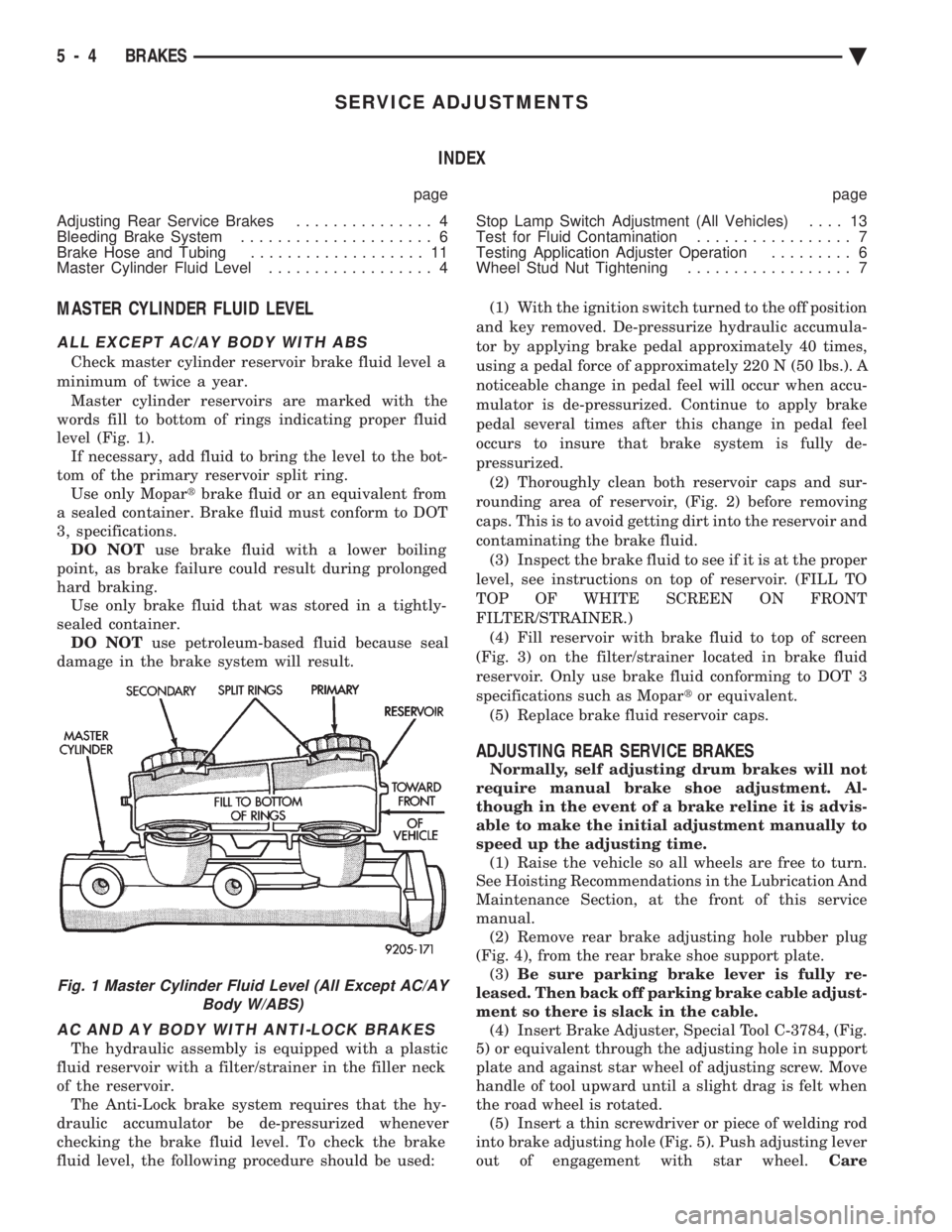
ALL EXCEPT AC/AY BODY WITH ABS
Check master cylinder reservoir brake fluid level a
minimum of twice a year. Master cylinder reservoirs are marked with the
words fill to bottom of rings indicating proper fluid
level (Fig. 1). If necessary, add fluid to bring the level to the bot-
tom of the primary reservoir split ring. Use only Mopar tbrake fluid or an equivalent from
a sealed container. Brake fluid must conform to DOT
3, specifications. DO NOT use brake fluid with a lower boiling
point, as brake failure could result during prolonged
hard braking. Use only brake fluid that was stored in a tightly-
sealed container. DO NOT use petroleum-based fluid because seal
damage in the brake system will result.
AC AND AY BODY WITH ANTI-LOCK BRAKES
The hydraulic assembly is equipped with a plastic
fluid reservoir with a filter/strainer in the filler neck
of the reservoir. The Anti-Lock brake system requires that the hy-
draulic accumulator be de-pressurized whenever
checking the brake fluid level. To check the brake
fluid level, the following procedure should be used: (1) With the ignition switch turned to the off position
and key removed. De-pressurize hydraulic accumula-
tor by applying brake pedal approximately 40 times,
using a pedal force of approximately 220 N (50 lbs.). A
noticeable change in pedal feel will occur when accu-
mulator is de-pressurized. Continue to apply brake
pedal several times after this change in pedal feel
occurs to insure that brake system is fully de-
pressurized. (2) Thoroughly clean both reservoir caps and sur-
rounding area of reservoir, (Fig. 2) before removing
caps. This is to avoid getting dirt into the reservoir and
contaminating the brake fluid. (3) Inspect the brake fluid to see if it is at the proper
level, see instructions on top of reservoir. (FILL TO
TOP OF WHITE SCREEN ON FRONT
FILTER/STRAINER.) (4) Fill reservoir with brake fluid to top of screen
(Fig. 3) on the filter/strainer located in brake fluid
reservoir. Only use brake fluid conforming to DOT 3
specifications such as Mopar tor equivalent.
(5) Replace brake fluid reservoir caps.
ADJUSTING REAR SERVICE BRAKES
Normally, self adjusting drum brakes will not
require manual brake shoe adjustment. Al-
though in the event of a brake reline it is advis-
able to make the initial adjustment manually to
speed up the adjusting time. (1) Raise the vehicle so all wheels are free to turn.
See Hoisting Recommendations in the Lubrication And
Maintenance Section, at the front of this service
manual. (2) Remove rear brake adjusting hole rubber plug
(Fig. 4), from the rear brake shoe support plate. (3) Be sure parking brake lever is fully re-
leased. Then back off parking brake cable adjust-
ment so there is slack in the cable. (4) Insert Brake Adjuster, Special Tool C-3784, (Fig.
5) or equivalent through the adjusting hole in support
plate and against star wheel of adjusting screw. Move
handle of tool upward until a slight drag is felt when
the road wheel is rotated. (5) Insert a thin screwdriver or piece of welding rod
into brake adjusting hole (Fig. 5). Push adjusting lever
out of engagement with star wheel. Care
Fig. 1 Master Cylinder Fluid Level (All Except AC/AY
Body W/ABS)
5 - 4 BRAKES Ä
Page 171 of 2438
If old springs have overheated or are damaged, re-
place. Overheating indications are paint discoloration
or distorted end coils. Varga brake springs are not
painted but overheating of the brake springs will be
noted by any Blueing of the springs.
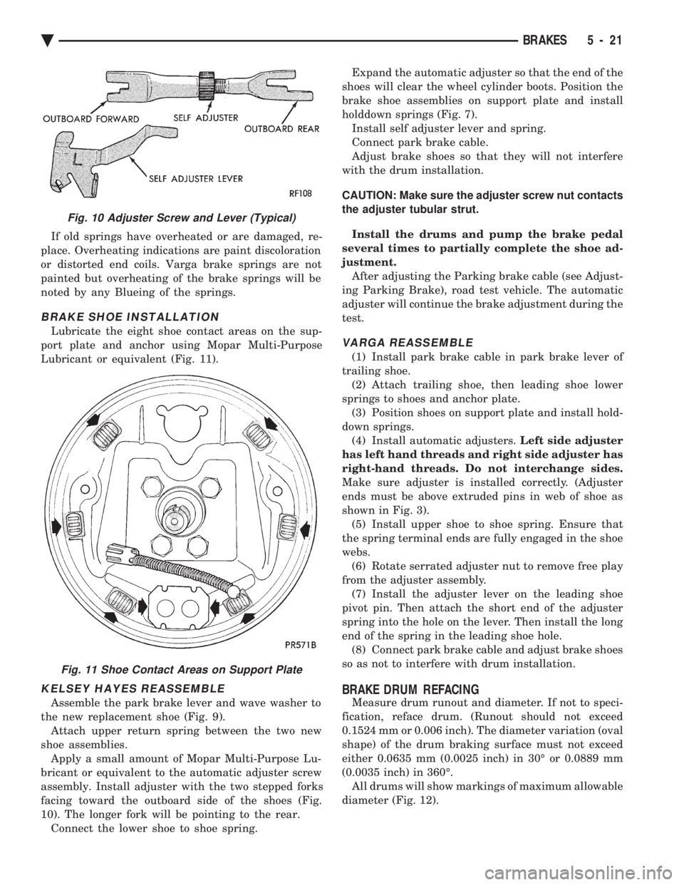
BRAKE SHOE INSTALLATION
Lubricate the eight shoe contact areas on the sup-
port plate and anchor using Mopar Multi-Purpose
Lubricant or equivalent (Fig. 11).
KELSEY HAYES REASSEMBLE
Assemble the park brake lever and wave washer to
the new replacement shoe (Fig. 9). Attach upper return spring between the two new
shoe assemblies. Apply a small amount of Mopar Multi-Purpose Lu-
bricant or equivalent to the automatic adjuster screw
assembly. Install adjuster with the two stepped forks
facing toward the outboard side of the shoes (Fig.
10). The longer fork will be pointing to the rear. Connect the lower shoe to shoe spring. Expand the automatic adjuster so that the end of the
shoes will clear the wheel cylinder boots. Position the
brake shoe assemblies on support plate and install
holddown springs (Fig. 7). Install self adjuster lever and spring.
Connect park brake cable.
Adjust brake shoes so that they will not interfere
with the drum installation.
CAUTION: Make sure the adjuster screw nut contacts
the adjuster tubular strut.
Install the drums and pump the brake pedal
several times to partially complete the shoe ad-
justment. After adjusting the Parking brake cable (see Adjust-
ing Parking Brake), road test vehicle. The automatic
adjuster will continue the brake adjustment during the
test.
VARGA REASSEMBLE
(1) Install park brake cable in park brake lever of
trailing shoe. (2) Attach trailing shoe, then leading shoe lower
springs to shoes and anchor plate. (3) Position shoes on support plate and install hold-
down springs. (4) Install automatic adjusters. Left side adjuster
has left hand threads and right side adjuster has
right-hand threads. Do not interchange sides.
Make sure adjuster is installed correctly. (Adjuster
ends must be above extruded pins in web of shoe as
shown in Fig. 3). (5) Install upper shoe to shoe spring. Ensure that
the spring terminal ends are fully engaged in the shoe
webs. (6) Rotate serrated adjuster nut to remove free play
from the adjuster assembly. (7) Install the adjuster lever on the leading shoe
pivot pin. Then attach the short end of the adjuster
spring into the hole on the lever. Then install the long
end of the spring in the leading shoe hole. (8) Connect park brake cable and adjust brake shoes
so as not to interfere with drum installation.
BRAKE DRUM REFACING
Measure drum runout and diameter. If not to speci-
fication, reface drum. (Runout should not exceed
0.1524 mm or 0.006 inch). The diameter variation (oval
shape) of the drum braking surface must not exceed
either 0.0635 mm (0.0025 inch) in 30É or 0.0889 mm
(0.0035 inch) in 360É. All drums will show markings of maximum allowable
diameter (Fig. 12).
Fig. 10 Adjuster Screw and Lever (Typical)
Fig. 11 Shoe Contact Areas on Support Plate
Ä BRAKES 5 - 21