door lock CHEVROLET DYNASTY 1993 Owner's Manual
[x] Cancel search | Manufacturer: CHEVROLET, Model Year: 1993, Model line: DYNASTY, Model: CHEVROLET DYNASTY 1993Pages: 2438, PDF Size: 74.98 MB
Page 697 of 2438
DOOR LOCK SYSTEM TEST
For complete testing of the AC, AG, AJ and AY
body automatic door lock systems, refer to the Body
Diagnostic Procedures Manual.
DOOR LOCK MOTOR REPLACEMENT
(1) Remove inside door release handle, window
regulator handle, if equipped and door trim panel. (2) Roll door watershield away from lower rear cor-
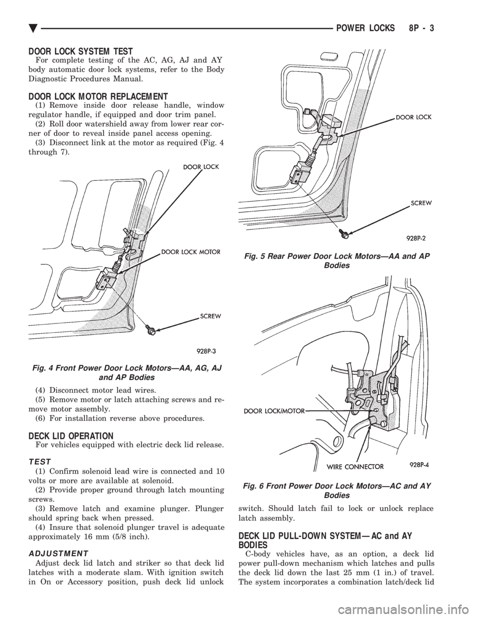
ner of door to reveal inside panel access opening. (3) Disconnect link at the motor as required (Fig. 4
through 7).
(4) Disconnect motor lead wires.
(5) Remove motor or latch attaching screws and re-
move motor assembly. (6) For installation reverse above procedures.
DECK LID OPERATION
For vehicles equipped with electric deck lid release.
TEST
(1) Confirm solenoid lead wire is connected and 10
volts or more are available at solenoid. (2) Provide proper ground through latch mounting
screws. (3) Remove latch and examine plunger. Plunger
should spring back when pressed. (4) Insure that solenoid plunger travel is adequate
approximately 16 mm (5/8 inch).
ADJUSTMENT
Adjust deck lid latch and striker so that deck lid
latches with a moderate slam. With ignition switch
in On or Accessory position, push deck lid unlock switch. Should latch fail to lock or unlock replace
latch assembly.
DECK LID PULL-DOWN SYSTEMÐAC and AY
BODIES
C-body vehicles have, as an option, a deck lid
power pull-down mechanism which latches and pulls
the deck lid down the last 25 mm (1 in.) of travel.
The system incorporates a combination latch/deck lid
Fig. 4 Front Power Door Lock MotorsÐAA, AG, AJ and AP Bodies
Fig. 5 Rear Power Door Lock MotorsÐAA and AP Bodies
Fig. 6 Front Power Door Lock MotorsÐAC and AY Bodies
Ä POWER LOCKS 8P - 3
Page 698 of 2438
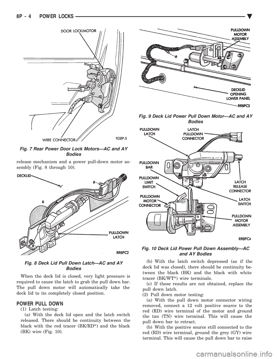
release mechanism and a power pull-down motor as-
sembly (Fig. 8 through 10). When the deck lid is closed, very light pressure is
required to cause the latch to grab the pull down bar.
The pull down motor will automatically take the
deck lid to its completely closed position.
POWER PULL DOWN
(1) Latch testing: (a) With the deck lid open and the latch switch
released. There should be continuity between the
black with the red tracer (BK/RD*) and the black
(BK) wire (Fig. 10). (b) With the latch switch depressed (as if the
deck lid was closed), there should be continuity be-
tween the black (BK) and the black with white
tracer (BK/WT*) wire terminals. (c) If these results are not obtained, replace the
pull down latch.
(2) Pull down motor testing: (a) With the pull down motor connector wiring
removed, connect a 12 volt positive source to the
red (RD) wire terminal of the motor and ground
the tan (TN) wire terminal. This will cause the
pull down bar to retract. (b) With the positive source still connected to the
red (RD) wire terminal, ground the grey (GY) wire
terminal. This will cause the pull down bar to raise
Fig. 7 Rear Power Door Lock MotorsÐAC and AY Bodies
Fig. 8 Deck Lid Pull Down LatchÐAC and AYBodies
Fig. 9 Deck Lid Power Pull Down MotorÐAC and AY Bodies
Fig. 10 Deck Lid Power Pull Down AssemblyÐACand AY Bodies
8P - 4 POWER LOCKS Ä
Page 699 of 2438
to the deck lid open position. If the pull down limit
switch is depressed at this time, the motor should
stop.(c) If these results are not obtained, replace the
pull down motor assembly.
REMOTE KEYLESS ENTRY
OPERATION
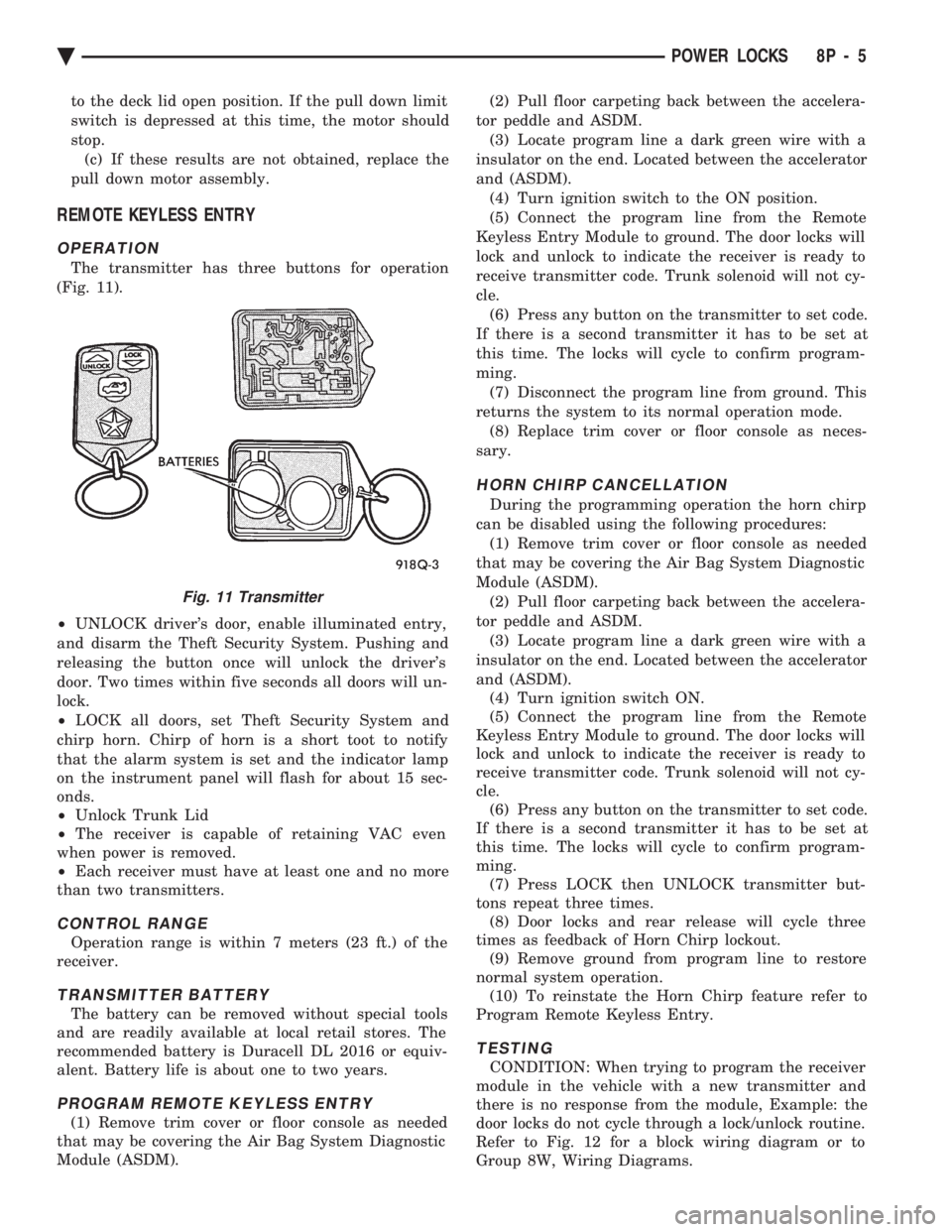
The transmitter has three buttons for operation
(Fig. 11).
² UNLOCK driver's door, enable illuminated entry,
and disarm the Theft Security System. Pushing and
releasing the button once will unlock the driver's
door. Two times within five seconds all doors will un-
lock.
² LOCK all doors, set Theft Security System and
chirp horn. Chirp of horn is a short toot to notify
that the alarm system is set and the indicator lamp
on the instrument panel will flash for about 15 sec-
onds.
² Unlock Trunk Lid
² The receiver is capable of retaining VAC even
when power is removed.
² Each receiver must have at least one and no more
than two transmitters.
CONTROL RANGE
Operation range is within 7 meters (23 ft.) of the
receiver.
TRANSMITTER BATTERY
The battery can be removed without special tools
and are readily available at local retail stores. The
recommended battery is Duracell DL 2016 or equiv-
alent. Battery life is about one to two years.
PROGRAM REMOTE KEYLESS ENTRY
(1) Remove trim cover or floor console as needed
that may be covering the Air Bag System Diagnostic
Module (ASDM). (2) Pull floor carpeting back between the accelera-
tor peddle and ASDM. (3) Locate program line a dark green wire with a
insulator on the end. Located between the accelerator
and (ASDM). (4) Turn ignition switch to the ON position.
(5) Connect the program line from the Remote
Keyless Entry Module to ground. The door locks will
lock and unlock to indicate the receiver is ready to
receive transmitter code. Trunk solenoid will not cy-
cle. (6) Press any button on the transmitter to set code.
If there is a second transmitter it has to be set at
this time. The locks will cycle to confirm program-
ming. (7) Disconnect the program line from ground. This
returns the system to its normal operation mode. (8) Replace trim cover or floor console as neces-
sary.
HORN CHIRP CANCELLATION
During the programming operation the horn chirp
can be disabled using the following procedures: (1) Remove trim cover or floor console as needed
that may be covering the Air Bag System Diagnostic
Module (ASDM). (2) Pull floor carpeting back between the accelera-
tor peddle and ASDM. (3) Locate program line a dark green wire with a
insulator on the end. Located between the accelerator
and (ASDM). (4) Turn ignition switch ON.
(5) Connect the program line from the Remote
Keyless Entry Module to ground. The door locks will
lock and unlock to indicate the receiver is ready to
receive transmitter code. Trunk solenoid will not cy-
cle. (6) Press any button on the transmitter to set code.
If there is a second transmitter it has to be set at
this time. The locks will cycle to confirm program-
ming. (7) Press LOCK then UNLOCK transmitter but-
tons repeat three times. (8) Door locks and rear release will cycle three
times as feedback of Horn Chirp lockout. (9) Remove ground from program line to restore
normal system operation. (10) To reinstate the Horn Chirp feature refer to
Program Remote Keyless Entry.
TESTING
CONDITION: When trying to program the receiver
module in the vehicle with a new transmitter and
there is no response from the module, Example: the
door locks do not cycle through a lock/unlock routine.
Refer to Fig. 12 for a block wiring diagram or to
Group 8W, Wiring Diagrams.
Fig. 11 Transmitter
Ä POWER LOCKS 8P - 5
Page 700 of 2438
(1) Be sure that the module has a battery feed
from the 20 Amp breaker in cavity 1 of the black
connector. Also affected would be the optical horn
and the stop lamps. (2) Be sure that the module has an ignition feed
from 5 Amp fuse in cavity 8 of the black connector.
Also affected would be the body computer, instru-
ment cluster and message center. (3) Be sure that the module has a ground from the
right side cowl behind the body computer to the cav-
ity 5 of the black connector. (4) Be sure that you are supplying a good ground
to the programming wire. (5) If the above circuits are good, replace the Re-
ceiver Module. CONDITION: Doors can be locked or unlocked with
the Keyless Entry transmitter. But the doors will not
lock. The Vehicle Theft Alarm system will not arm,
when using only the power door LOCK switch in the
driver's door. (1) Be sure you have not left key in the ignition
column lock cylinder. (2) If step 1 is OK, check the Key in Lock switch
circuit in the steering column for a short to ground. (3) In this problem the body computer controls the
LOCK function. Be sure that it is providing a battery
voltage output to the door lock relay. The door lock
relay controls the door lock motors. CONDITION: Doors will lock but Vehicle Theft
System will not arm when using the transmitter. (1) The Keyless Entry Receiver Module controls
the door lock signal to the door lock relay. The door
lock relay controls the door lock motors. Check for
battery voltage at cavity 10 of the Theft Alarm mod-
ule from the Receiver module. (2) If voltage is OK, replace Receiver module.
CONDITION: All doors except driver's door will
lock with the transmitter. (1) Test the driver's door output of the Receiver
Module for a ground. (2) If there is no ground at the pin, replace the Re-
ceiver module. (3) If there is a ground at the output, replace the
door lock motor. CONDITION: Only driver's door will lock with the
transmitter.
² Repair ground circuit to unlock relay
² Replace unlock relay
CONDITION: Doors do not lock with the transmit-
ter, but still get horn CHIRP that indicates that they
did lock. Replace Receiver module. CONDITION: Doors will lock with the transmitter
but there is no horn CHIRP. (1) Press horn button, listen horn sound.
(2) If the horn sounded, change horn relay. (3) Still no CHIRP, check continuity between the
horn relay and the receiver output pin. Repair as
necessary. (4) Still no horn CHIRP, replace the receiver mod-
ule. (5) If using a DRB II, refer to Body Diagnostic Pro-
cedures.
REMOTE KEYLESS MODULE REPLACEMENT
(1) Remove lower right instrument panel silencer.
(2) Remove glove box assembly.
(3) Remove three screws attaching the mounting
bracket to instrument panel. (4) Lower bracket and module assembly, to discon-
nect wire connector. (5) Remove two screws attaching the Remote Key-
less entry Module to bracket. (6) Remove two screws attaching the security mod-
ule to bracket. (7) To installation reverse above procedures.
LAMP OUTAGE MODULE REPLACEMENT
(1) Remove lower right instrument panel silencer.
(2) Remove glove box and ash receiver module.
(3) Remove three screws attaching the mounting
bracket to instrument panel. (4) Lower bracket and module assembly, to discon-
nect wire connectors. (5) Remove two screws attaching the Lamp Outage
Module to bracket. (6) Remove two screws attaching the security mod-
ule to bracket. (7) To installation reverse above procedures.
DOOR LOCK INHIBIT
The power door lock inhibit system prevents the
doors from being locked using the power door locks
when either of two conditions occur: (1) The key is in the ignition switch and any of the
doors are open. The ignition switch does not have to
be ON. (2) The key is in the ignition switch and the head-
lamp are on.
AC, AG, AJ AND AY BODIES
With the ignition switch in the ON or OFF position
and the driver's door open the Body Controller will
ignore the command to lock the power door locks.
Once the key is removed, or the driver's door is
closed, the Body Controller will allow the power door
locks to lock. Refer to Body Diagnostic Procedure
Manual for further testing procedures.
8P - 6 POWER LOCKS Ä
Page 702 of 2438
AA BODY
Uses a power door lock inhibit relay. The relay is
located above the glove box compartment.
INHIBIT RELAY
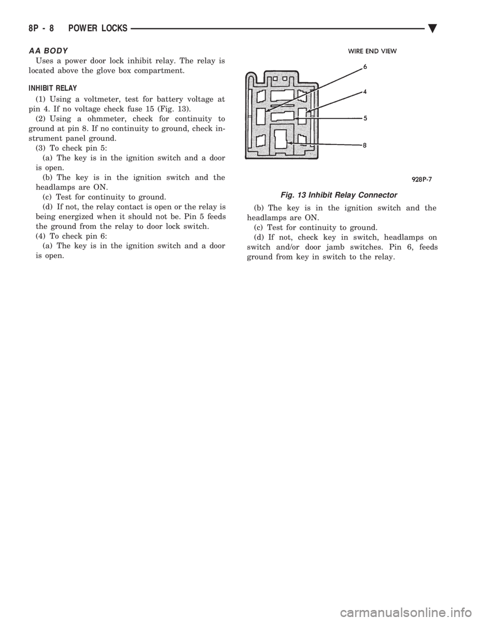
(1) Using a voltmeter, test for battery voltage at
pin 4. If no voltage check fuse 15 (Fig. 13). (2) Using a ohmmeter, check for continuity to
ground at pin 8. If no continuity to ground, check in-
strument panel ground. (3) To check pin 5:(a) The key is in the ignition switch and a door
is open. (b) The key is in the ignition switch and the
headlamps are ON. (c) Test for continuity to ground.
(d) If not, the relay contact is open or the relay is
being energized when it should not be. Pin 5 feeds
the ground from the relay to door lock switch.
(4) To check pin 6: (a) The key is in the ignition switch and a door
is open. (b) The key is in the ignition switch and the
headlamps are ON. (c) Test for continuity to ground.
(d) If not, check key in switch, headlamps on
switch and/or door jamb switches. Pin 6, feeds
ground from key in switch to the relay.
Fig. 13 Inhibit Relay Connector
8P - 8 POWER LOCKS Ä
Page 703 of 2438
VEHICLE THEFT SECURITY SYSTEM
CONTENTS
page page
GENERAL INFORMATION .................. 1
SECURITY SYSTEM DOOR SWITCH REPLACEMENT ........................ 2
SECURITY SYSTEM HOOD SWITCH REPLACEMENT ........................ 2 SYSTEM SELF-TESTS
.................... 1
VEHICLE THEFT SECURITY SYSTEM MODULE REPLACEMENT ........................ 2
WHAT WILL TRIGGER THE SYSTEM ........ 1
GENERAL INFORMATION
JUMP-STARTING, VEHICLE EQUIPPED
WITH THEFT SECURITY SYSTEM . After the
booster battery has been connected, the Theft System
must be turned OFF. Using the key, lock then un-
lock either front door. This turns the Theft System
OFF and the remainder of the Jump-Starting proce-
dure can be followed. If this procedure is not followed, the Theft System
electronics will prevent the engine from starting. If a new Powertrain Control Module is installed,
the engine has to be cranked 20 times before the
alarm system activated. This passive system is designed to protect against
whole vehicle theft. The system monitors vehicle
doors, hood, trunk key cylinder, and ignition action
for unauthorized operation. The alarm activates by
sounding the horn, flashing the park and tail lamps,
and providing an engine kill feature (Fig. 1). Passive arming occurs upon normal vehicle exit,
open door, lock with power locks, close door. The SET
lamp in the panel will flash for 15 seconds, indicat-
ing that arming is in progress. If no monitored sys-
tems are activated during this period, the system
will arm. If the hood or trunk key cylinder switches
are not sensed by the system. The SET lamp will re-
main lit during the arming process, although the sys-
tem will still arm. The system is to be considered as
an active armed system when using the Remote Key-
less Entry. If the SET lamp does not illuminate at all
upon door closing it indicates that the system is not
arming. Passive disarming occurs upon normal vehicle en-
try unlocking either door with the key, or unlocking
using the Remote Keyless transmitter. This disarm-
ing will also halt the alarm once it has been acti-
vated. Whenever the battery is disconnected and recon-
nected, the Vehicle Theft Security System enters
power up alarm mode which flashes the park and tail
lamps and prevents the engine from running. To exit
this mode, the system must be disarmed as men-
tioned above. A tamper alert exists to notify the driver that the
alarm had been activated, and the alarm has since
timed-out for more than 18 minutes. This alert con-
sists of 3 horn pulses when the vehicle is disarmed. The alarm system will not arm if the doors are
manually locked, providing a manual override of the
alarm.
WHAT WILL TRIGGER THE SYSTEM
One of the following actions will trigger the system
while it is armed. Without properly disarming sys-
tem, by using the key or the remote transmitter. (1) Opening the HOOD.
(2) Opening any DOOR.
(3) Removing the TRUNK KEY CYLINDER.
(4) Turning the IGNITION ON.
(5) The ignition switch can be turned to the acces-
sory position without triggering alarm system.
SYSTEM SELF-TESTS
A diagnostics mode is available in the system to
verify operation of all monitored switches or circuits.
To enter diagnostics, cycle the ignition key to the ac-
cessory position 3 times, leaving the key in this po-
sition. Upon entering diagnostics, the park and tail lamps
will begin flashing to verify their operation. In addi-
tion, the horn will sound twice to indicate that the
trunk key cylinder is in its proper position. Return-
ing the ignition to the OFF position will stop the
lamps from flashing while keeping the system in di-
agnostics. While in diagnostics mode, a horn pulse should oc-
cur at each of the following events indicating proper
operation: (1) Beginning with all doors closed, open then close
each door. The horn will sound when the door ajar
switch closes, and then again when the switch opens.
There must b e a 1 second delay between closing and
opening the switch. (2) Open, then close the hood. The horn will sound
when the hood is opened, and again when it is closed.
Ä VEHICLE THEFT SECURITY SYSTEM 8Q - 1
Page 704 of 2438
(3) Activate the power door locks in both the
LOCK and UNLOCK directions. The horn will sound
after each activation. (4) Rotate the key in each of the door lock cylin-
ders to the unlock position. The horn will sound as
the switch closes, and again when it opens. There
must b e a 1 second delay between changing switch
states, or the horn will not sound.
² Press the LOCK button,horn will sound.
² Press the UNLOCK button, horn will sound.
(5) Cycle the key to the ignition RUN position. A
single horn pulse will indicate proper operation of
the ignition input. This will also take the module out
of the diagnostics mode. For any of these tests, if the
switch does not remain open or closed for at least 1
second, the horn will only sound once. The lack of a horn pulse, during any operation, in-
dicates a switch failure. Check for continuity at the
switch, if this is good, check for an open or shorted
wire between the switch and alarm module. Also,
check if a new powertrain control module has been
installed recently. Vehicle Theft Security System will
not function until 20 engine cranks. Whenever a Vehicle Theft Security System mal-
function occurs, first verify that the wire harness is
properly connected to all connectors before starting
normal diagnosis and repair procedures. Refer to Ve-
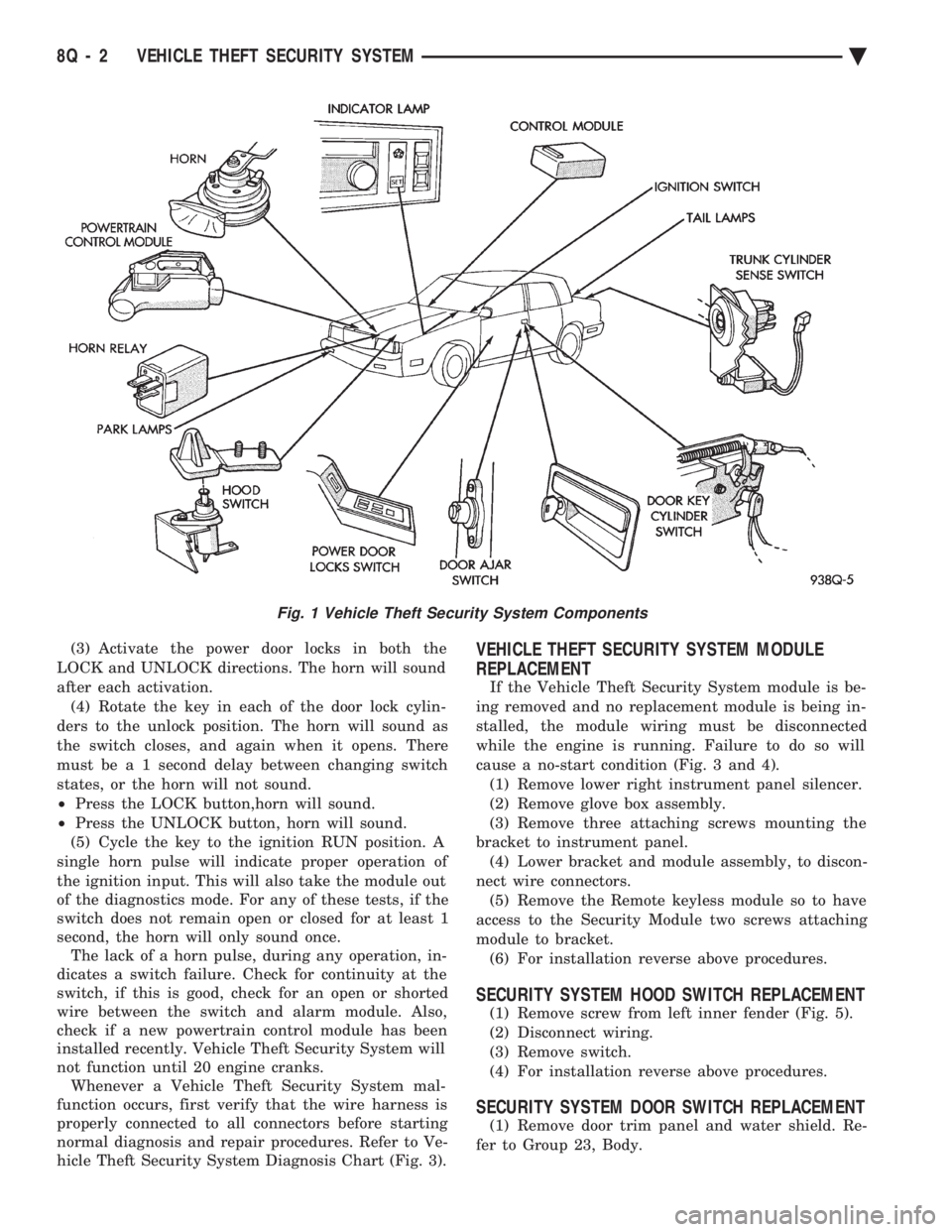
hicle Theft Security System Diagnosis Chart (Fig. 3).VEHICLE THEFT SECURITY SYSTEM MODULE
REPLACEMENT
If the Vehicle Theft Security System module is be-
ing removed and no replacement module is being in-
stalled, the module wiring must be disconnected
while the engine is running. Failure to do so will
cause a no-start condition (Fig. 3 and 4). (1) Remove lower right instrument panel silencer.
(2) Remove glove box assembly.
(3) Remove three attaching screws mounting the
bracket to instrument panel. (4) Lower bracket and module assembly, to discon-
nect wire connectors. (5) Remove the Remote keyless module so to have
access to the Security Module two screws attaching
module to bracket. (6) For installation reverse above procedures.
SECURITY SYSTEM HOOD SWITCH REPLACEMENT
(1) Remove screw from left inner fender (Fig. 5).
(2) Disconnect wiring.
(3) Remove switch.
(4) For installation reverse above procedures.
SECURITY SYSTEM DOOR SWITCH REPLACEMENT
(1) Remove door trim panel and water shield. Re-
fer to Group 23, Body.
Fig. 1 Vehicle Theft Security System Components
8Q - 2 VEHICLE THEFT SECURITY SYSTEM Ä
Page 715 of 2438
above. When the control module has finished, it will
return to the normal operating mode after ten sec-
onds if no further switches are activated.The control module will also return to normal op-
erating mode if any manual seat or recliner move-
ment switch is actuated during the ten second
timeout. If the system has found a problem, refer to the ap-
propriate diagnosis condition.
POWER MEMORY SEAT, RECLINER AND
MIRRORS DIAGNOSIS
Before any diagnosis is done on the system, move
the seat switches and listen for relays clicking in the
control module under the seat. If relays can be heard,
the main battery and ground circuits to the control
module as well as the battery circuit to the switches
in the driver's door are good. When checking for voltage or continuity, always
use a volt/ohm meter to get accurate readings. The
seat and recliner switches must be activated to check
for voltage at the seat and recliner motors or at the
input to the control module from the switches. The control module creates a special voltage supply
for the position sensing functions. It also shuts down
after five seconds, in order to check this or any other
voltage being fed back to the control module. A
switch may have to be activated more than once to
verify a voltage reading. The voltage from the con-
trol module that feeds the seat and recliner position
sensing potentiometer, will be between 4.5 to 5 volts.
For simplicity in the diagnosis section, the feed volt-
age will be called 5 volts. On the position sensing
wires, these voltages will always be less than 5 volts
but more than 0 volts. Typically the high level is at
a maximum of about 4.25 volts and the low level can
be as little as 0.1 volts. If any seat or recliner potentiometer or mirror
rheostat position sense wires are crossed, the control
module will not move that part of the system. The
seat or mirror will be in a fault diagnostic mode.
CONDITION: SYSTEM WILL NOT OPERATE.
PROCEDURE
(1) Check for forward/rearward operation of re-
cliner. If not operable, check for an open or loose cir-
cuit breaker mounted in board on the relay bank in
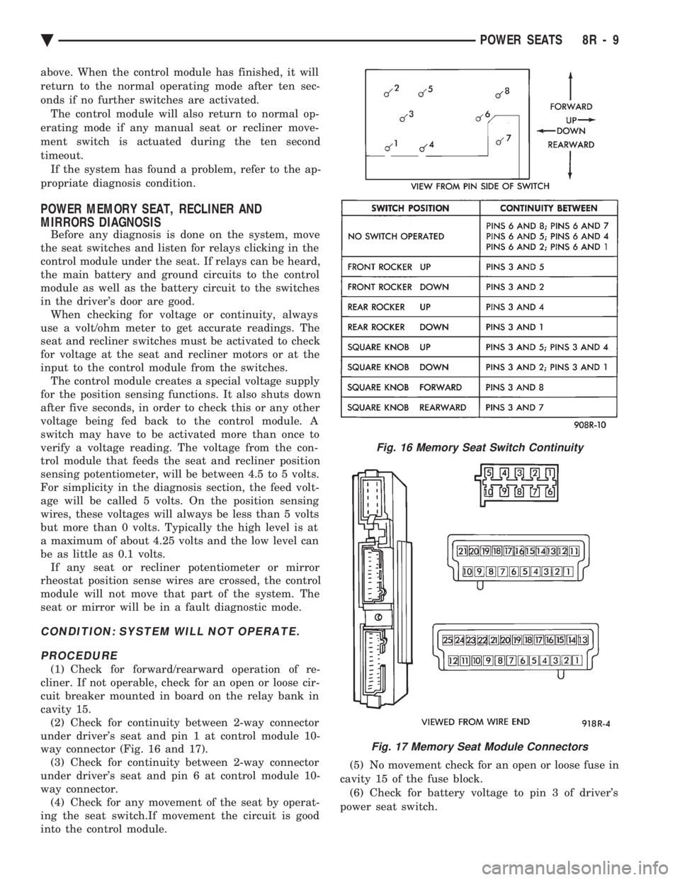
cavity 15. (2) Check for continuity between 2-way connector
under driver's seat and pin 1 at control module 10-
way connector (Fig. 16 and 17). (3) Check for continuity between 2-way connector
under driver's seat and pin 6 at control module 10-
way connector. (4) Check for any movement of the seat by operat-
ing the seat switch.If movement the circuit is good
into the control module. (5) No movement check for an open or loose fuse in
cavity 15 of the fuse block. (6) Check for battery voltage to pin 3 of driver's
power seat switch.
Fig. 16 Memory Seat Switch Continuity
Fig. 17 Memory Seat Module Connectors
Ä POWER SEATS 8R - 9
Page 719 of 2438
ity 9 and pin 7 of the control module 25-way connec-
tor. The vehicle speed sensor signal can be tested
with a volt/ohmmeter at pin 7 of the control module
25-way connector. Turn on the vehicle ignition and
check fo r a 5 volt signal as the vehicle is moved
about 3 to 5 feet. If not repair open wiring, terminal
push out, bad crimp, drive in vehicle speed sensor,
etc., as necessary to correct condition. Ensure that
the 25-way connector is plugged into the control
module securely. Road test vehicle after repairs have
been made to ensure that no recalls can occur while
moving.
CONDITION: INSTRUMENT CLUSTER SPEEDOMETER STAYS AT 0 MPH/ (0 KM/H)WHILE VEHICLE IS MOVING, BODYCOMPUTER DOES NOT LOCK DOORS AT 15MPH (24 KM/H), AND THE SPEED CONTROLWILL NOT ACCEPT A SPEED SET.
PROCEDURE
(1) Remove driver's seat anchor bolts and nuts. Ad-
just the driver's seat to a safe driving position. Dis-
connect the 25-way connector from the memory seat
control module. Replace the driver's seat anchor bolts
and nuts. Road test the vehicle to complete this diag-
nosis. If the doors lock, the cruise control accepts a
set, and the speedometer now works, replace the
Memory Seat control module. (2) After replacing the Memory Seat control mod-
ule, perform the memory seat diagnostic self tests.
This teaches the new module it's soft limits and now
re-road test the vehicle before returning it to the cus-
tomer.
CONDITION: NO SEAT MOVEMENT IN THE RECALL MODE, SEAT WILL MOVE BYMANUAL SWITCH ACTUATION IN ALLDIRECTIONS WITHOUT STALL DETECTION.
PROCEDURE
(1) Check for 5 volts at pin 10 of the control mod-
ule 25-way connector. This is the 5 volt feed from the
control module to the seat track position sensing po-
tentiometer. (2) Check for ground at pin 8 of the control module
25-way connector. To test for ground, one lead of the
voltmeter must be connected to either the 5 volt sup-
ply for the control module or the battery positive. If
the sense voltage and ground are NOT present at the
above pins of the 21-way control module connector.
When the seat switch is pressed, replace the control
module. An inadvertent application of battery volt-
age to the circuit could damaged the control module.
If the voltage and ground circuits are present then
continue this procedure. (3) Check for 5 volts at pin 5 of the natural 5-way
connector plugged into the power seat adjuster mo-
tors end-bell. (4) Check for ground at pin 4 of the natural 5-way
connector plugged into the power seat adjuster mo-
tors end-bell. If the power seat adjuster still has no
movement in the recall mode, then continue this pro-
cedure. (5) Disconnect the natural 5-way connector from
the power seat adjuster motors end-bell. (6) Check with an ohmmeter for a resistance read-
ing that may be from 2600 to 4000 ohms between
pins 4 and 5 of the motors end-bell connector. If
there is an open circuit reading or the reading ob-
tained falls outside this range, then replace the seat
motor package assembly. After replacement of the
seat motor package, reconnect all wiring connectors
and reinstall seat assembly in vehicle. Operate the
switches manually to cause maximum seat move-
ment in all directions. Perform the memory seat di-
agnostic self check so the control module will learn
the new soft limits of the assembly.
CONDITION: NO SEAT TRACK FORWARD OR REARWARD MOVEMENT IN THE RECALLMODE, SEAT TRACK WILL MOVE FORWARDOR REARWARD BY MANUAL SWITCHACTUATION WITHOUT STALL DETECTION.
PROCEDURE
(1) Check for a voltage at pin 12 of the control
module 21-way connector. Less than 5 volts for the
seat track fully forward and more than 0 volts when
fully rearward. This voltage should vary correspond-
ing to the position. (2) Check for a voltage at pin 1 of the natural
5-way connector, Same as in step (1) above. The
ground lead connected to pin 4 of the 5-way connec-
tor. If the voltage reading is at 0 volts, disconnect
the 5-way natural connector and check for a short to
ground in the harness. If no short is found, reconnect
the connector and continue the procedure. (3) Check for the voltage to vary as noted above, if
it does not vary as the seat track is moved forward
and rearward, the sensing potentiometer is defective.
Replace the seat motor package assembly. After re-
placement of the seat motor package, reconnect all
wiring connectors and reinstall seat assembly in ve-
hicle. Operate the switches manually to cause maxi-
mum seat movement in all directions. Perform the
memory seat diagnostic self check so the control
module will learn the new soft limits of the assem-
bly.
Ä POWER SEATS 8R - 13
Page 721 of 2438
(3) Use an ohmmeter to test the wiring between
the door switch and the control module in the driv-
er's seat. The circuits should be disconnected from
their components at each end. Repair the wiring as
required for open circuits, terminal push outs, or bad
crimps. If the circuits are good to the control module
but the function is still missing, replace the control
module.
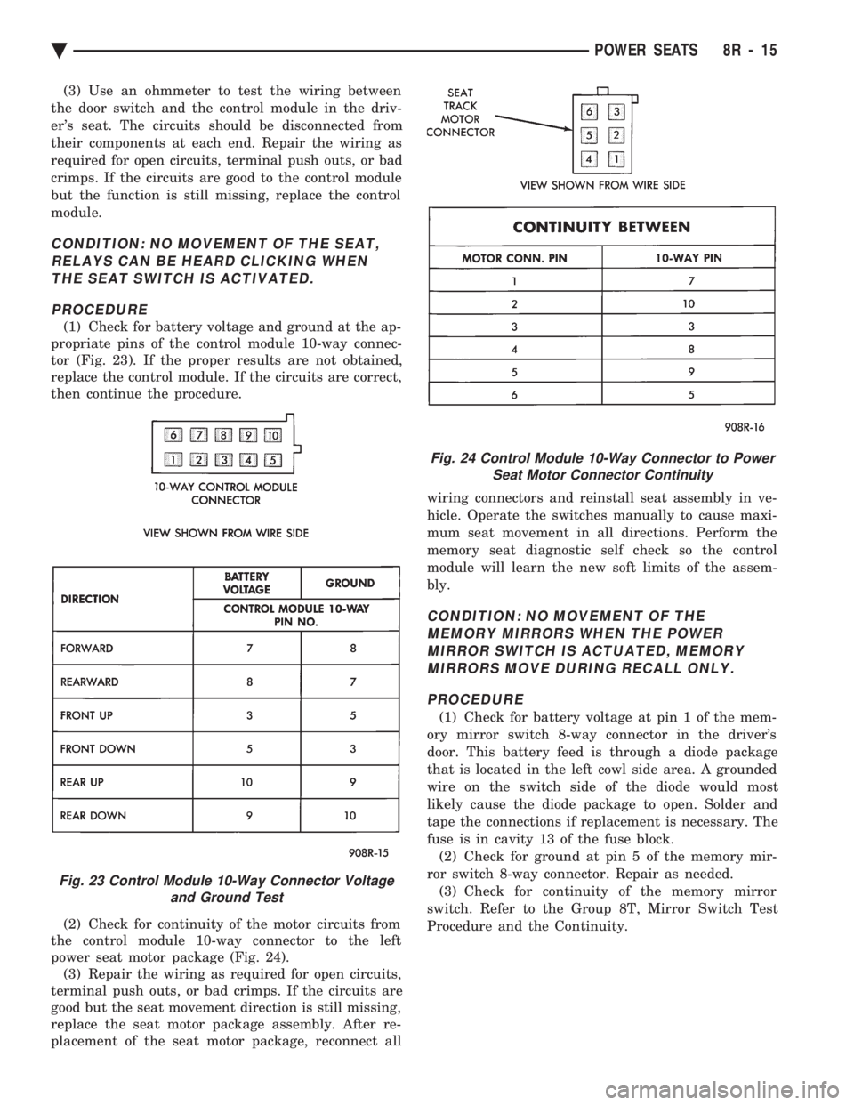
CONDITION: NO MOVEMENT OF THE SEAT, RELAYS CAN BE HEARD CLICKING WHENTHE SEAT SWITCH IS ACTIVATED.
PROCEDURE
(1) Check for battery voltage and ground at the ap-
propriate pins of the control module 10-way connec-
tor (Fig. 23). If the proper results are not obtained,
replace the control module. If the circuits are correct,
then continue the procedure.
(2) Check for continuity of the motor circuits from
the control module 10-way connector to the left
power seat motor package (Fig. 24). (3) Repair the wiring as required for open circuits,
terminal push outs, or bad crimps. If the circuits are
good but the seat movement direction is still missing,
replace the seat motor package assembly. After re-
placement of the seat motor package, reconnect all wiring connectors and reinstall seat assembly in ve-
hicle. Operate the switches manually to cause maxi-
mum seat movement in all directions. Perform the
memory seat diagnostic self check so the control
module will learn the new soft limits of the assem-
bly.
CONDITION: NO MOVEMENT OF THE MEMORY MIRRORS WHEN THE POWERMIRROR SWITCH IS ACTUATED, MEMORYMIRRORS MOVE DURING RECALL ONLY.
PROCEDURE
(1) Check for battery voltage at pin 1 of the mem-
ory mirror switch 8-way connector in the driver's
door. This battery feed is through a diode package
that is located in the left cowl side area. A grounded
wire on the switch side of the diode would most
likely cause the diode package to open. Solder and
tape the connections if replacement is necessary. The
fuse is in cavity 13 of the fuse block. (2) Check for ground at pin 5 of the memory mir-
ror switch 8-way connector. Repair as needed. (3) Check for continuity of the memory mirror
switch. Refer to the Group 8T, Mirror Switch Test
Procedure and the Continuity.
Fig. 23 Control Module 10-Way Connector Voltage and Ground Test
Fig. 24 Control Module 10-Way Connector to PowerSeat Motor Connector Continuity
Ä POWER SEATS 8R - 15