oil filter CHEVROLET DYNASTY 1993 Owner's Manual
[x] Cancel search | Manufacturer: CHEVROLET, Model Year: 1993, Model line: DYNASTY, Model: CHEVROLET DYNASTY 1993Pages: 2438, PDF Size: 74.98 MB
Page 1624 of 2438
OIL PAN
A formed steel oil pan provides lower engine pro-
tection as well as serving as the engine oil reservoir
(Fig. 1). Pan side flanges to block are sealed with
gaskets. The oil pickup tube for some 2.2L engines
have a circular strainer and cover. The 2.5L engine
pickup is also unsupported and the lower end has a
box type strainer (Fig. 4).
PRESSURE LUBRICATION
Oil drawn up through the pickup tube is pressur-
ized by the pump and routed through the full flow
filter to the main oil gallery running the length of
the cylinder block (Fig. 2). Modified oil pickup, pump
and check valve provide increased oil flow to the
main oil gallery.
MAIN/ROD BEARINGS
A diagonal hole in each bulkhead feeds oil to each
main bearing. Drilled passages within the crankshaft
route oil from main bearing journals to crankpin
journals.
ACCESSORY SHAFT
Two separate holes supply the accessory shaft for
the N/A engines. For Turbo III engines there is a slot
in the rear shaft bushing that squirts oil onto the
oil pump drive gears (Fig. 2).
BALANCE SHAFTS
The engine balance shafts are lubricated by an ad-
ditional hole that interconnects a passage in one leg
of the balance shaft carrier to route oil down to the
carrier oil gallery. This gallery directly supplies the
balance shafts front bearings and internal machined
passages in the shafts routes oil from front to rear
shaft bearing journals.
TURBOCHARGER (WHERE EQUIPPED)
If turbocharger equipped, pressurized oil from the
main gallery to sending unit hex fitting is piped from
the fitting to the turbocharger bearing housing.
From the housing a hose and tube connection to a
machined hole in the block provides drainback.
CAMSHAFT/HYDRAULIC LIFTERS
A vertical hole at the number five bulkhead routes
pressurized oil through a restrictor up past a cylinder
head bolt to an oil gallery running the length of the
cylinder head. For 2.2/2.5L and 2.5L FFV engines
hydraulic adjusters are supplied directly from this
gallery while diagonal holes supply oil to the cam-
shaft journals. The camshaft journals are partially
slotted to allow a predetermined amount of pressur-
ized oil to pass into the bearing cap cavities with
small holes directed to spray lubricate the camshaft
lobes. For Turbo III engines oil is supplied thru oil
galleries in the head to the camshafts and rocker arm shafts which feed oil to the lash adjusters. Oil is
feed thru the rocker arms to lubricate the rollers and
the camshaft lobes.
SPLASH LUBRICATION
Oil returning to the pan from pressurized compo-
nents supplies lubrication to the valve stems. Cylinder
bores and wrist pins are splash lubricated from di-
rected holes in the connecting rods.
OIL PAN
REMOVAL
(1) Drain engine oil and remove oil pan.
(2) Clean oil pan and all gasket surfaces.
OIL PAN RAIL TO BLOCK SEALING
For all engines side gaskets (Fig. 1) are employed for
rail sealing.
INSTALLATION
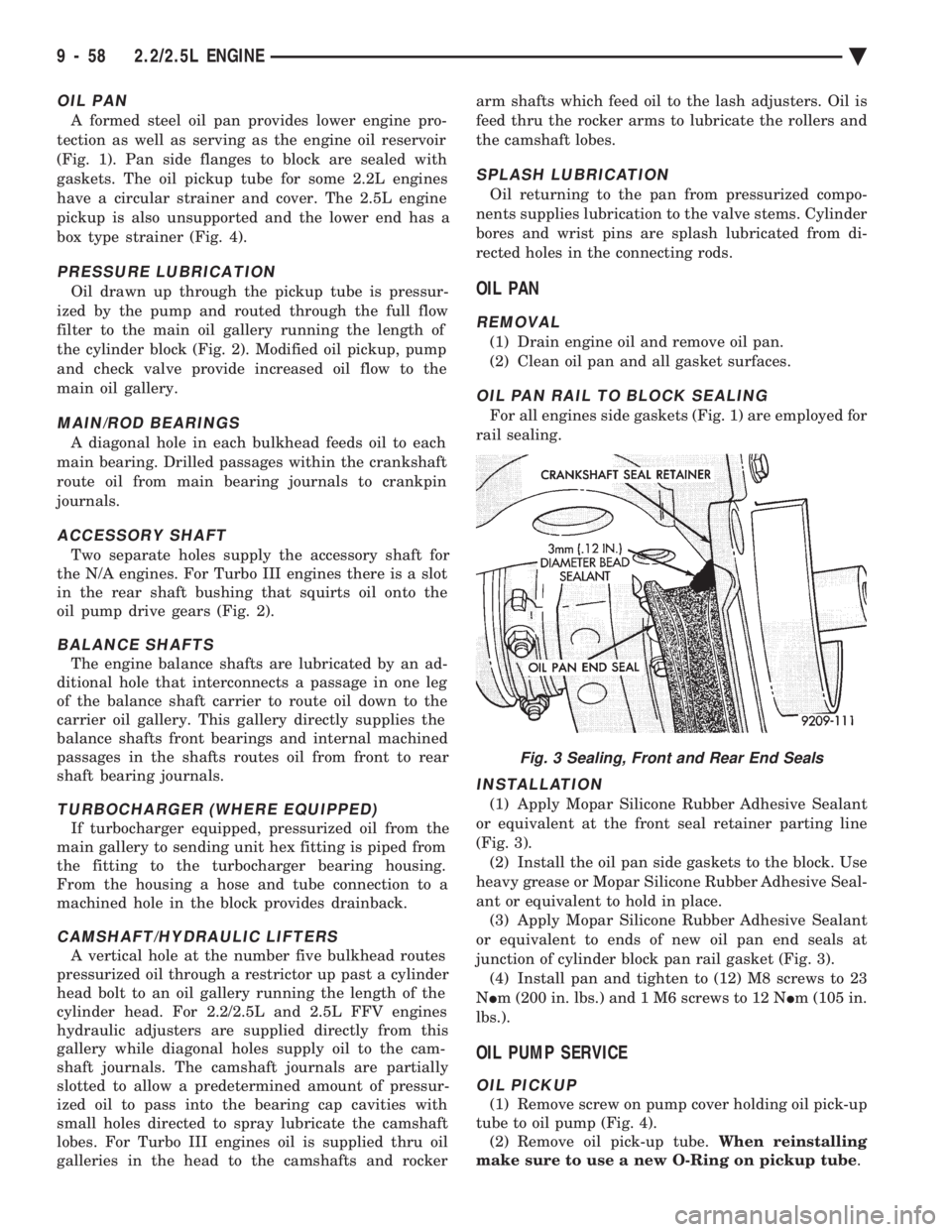
(1) Apply Mopar Silicone Rubber Adhesive Sealant
or equivalent at the front seal retainer parting line
(Fig. 3). (2) Install the oil pan side gaskets to the block. Use
heavy grease or Mopar Silicone Rubber Adhesive Seal-
ant or equivalent to hold in place. (3) Apply Mopar Silicone Rubber Adhesive Sealant
or equivalent to ends of new oil pan end seals at
junction of cylinder block pan rail gasket (Fig. 3). (4) Install pan and tighten to (12) M8 screws to 23
N Im (200 in. lbs.) and 1 M6 screws to 12 N Im (105 in.
lbs.).
OIL PUMP SERVICE
OIL PICKUP
(1) Remove screw on pump cover holding oil pick-up
tube to oil pump (Fig. 4). (2) Remove oil pick-up tube. When reinstalling
make sure to use a new O-Ring on pickup tube .
Fig. 3 Sealing, Front and Rear End Seals
9 - 58 2.2/2.5L ENGINE Ä
Page 1627 of 2438
(3) Oil Pressure: Curb Idle25 kPa (4 psi) mini-
mum 3000 RPM 170-550 kPa (25-80 psi).
OIL FILTER
ANTI-DRAIN BACK VALVE
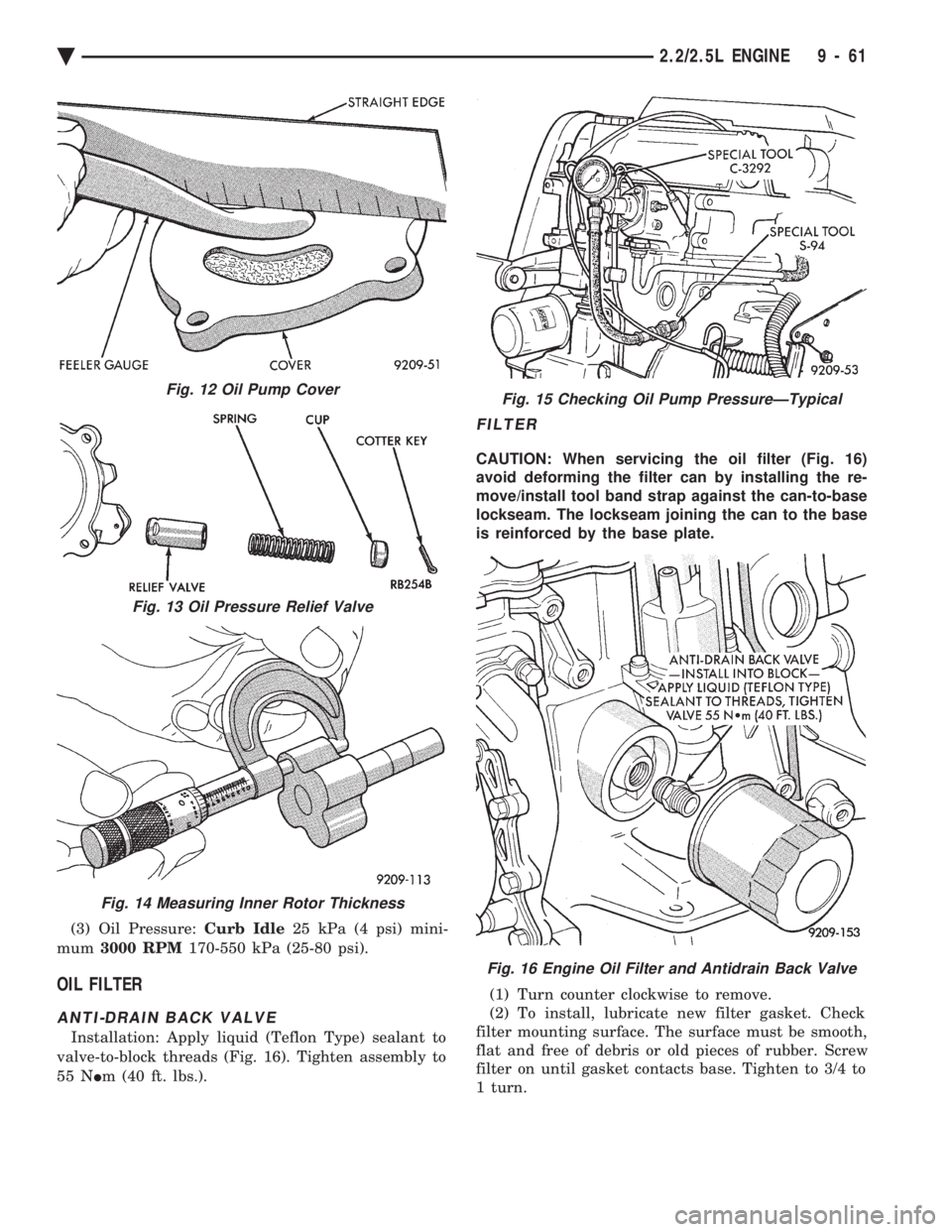
Installation: Apply liquid (Teflon Type) sealant to
valve-to-block threads (Fig. 16). Tighten assembly to
55 N Im (40 ft. lbs.).
FILTER
CAUTION: When servicing the oil filter (Fig. 16)
avoid deforming the filter can by installing the re-
move/install tool band strap against the can-to-base
lockseam. The lockseam joining the can to the base
is reinforced by the base plate.
(1) Turn counter clockwise to remove.
(2) To install, lubricate new filter gasket. Check
filter mounting surface. The surface must be smooth,
flat and free of debris or old pieces of rubber. Screw
filter on until gasket contacts base. Tighten to 3/4 to
1 turn.
Fig. 12 Oil Pump Cover
Fig. 13 Oil Pressure Relief Valve
Fig. 14 Measuring Inner Rotor Thickness
Fig. 15 Checking Oil Pump PressureÐTypical
Fig. 16 Engine Oil Filter and Antidrain Back Valve
Ä 2.2/2.5L ENGINE 9 - 61
Page 1632 of 2438
3.0L ENGINE INDEX
page page
Accessory Drive Belt Service ................ 70
Auto Lash Adjuster ....................... 75
Camshaft Service ........................ 76
Checking Engine Oil Pressure ............... 93
Crankshaft and Cylinder Block, Assembly Service . 86
Cylinder Block ........................... 89
Cylinder Head ........................... 78
Cylinder Head and Camshaft Service ......... 75
Engine Assembly ......................... 69
Engine Lubrication System ................. 91
Engine Mounts .......................... 68 Engine Specifications
..................... 95
General Information ....................... 66
Oil Filter and Bracket ..................... 94
Oil Pan ................................ 92
Oil Pump Service ........................ 92
Piston and Connecting Rod Assembly Service . . . 82
Timing Belt InspectionÐIn Vehicle ............ 72
Timing Belt Service ....................... 72
Valve Service ........................... 80
GENERAL INFORMATION
ENGINE IDENTIFICATION NUMBER OR CODE
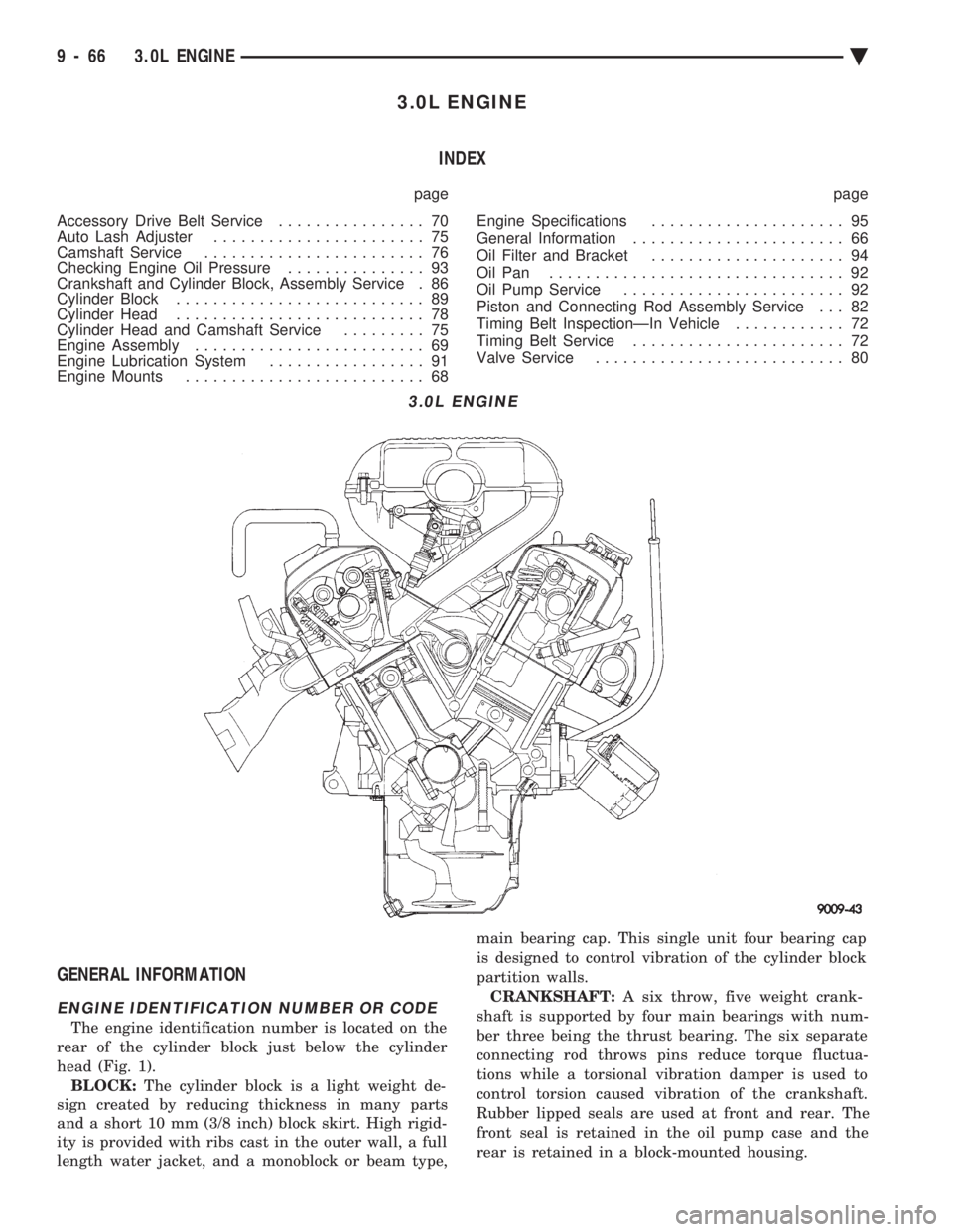
The engine identification number is located on the
rear of the cylinder block just below the cylinder
head (Fig. 1). BLOCK: The cylinder block is a light weight de-
sign created by reducing thickness in many parts
and a short 10 mm (3/8 inch) block skirt. High rigid-
ity is provided with ribs cast in the outer wall, a full
length water jacket, and a monoblock or beam type, main bearing cap. This single unit four bearing cap
is designed to control vibration of the cylinder block
partition walls.
CRANKSHAFT: A six throw, five weight crank-
shaft is supported by four main bearings with num-
ber three being the thrust bearing. The six separate
connecting rod throws pins reduce torque fluctua-
tions while a torsional vibration damper is used to
control torsion caused vibration of the crankshaft.
Rubber lipped seals are used at front and rear. The
front seal is retained in the oil pump case and the
rear is retained in a block-mounted housing.
3.0L ENGINE
9 - 66 3.0L ENGINE Ä
Page 1657 of 2438
(clearance between piston O.D. and cylinder) minus
0.02 mm which is the boring margin. (3) Bore all cylinders to calculated boring finish di-
mension. Then bore the final finish dimension (piston
O.D. plus cylinder clearance). (4) Check clearance between piston and cylinder,
clearance should be 0.03 to 0.05 mm (.0012 to .002
inch).
ENGINE LUBRICATION SYSTEM
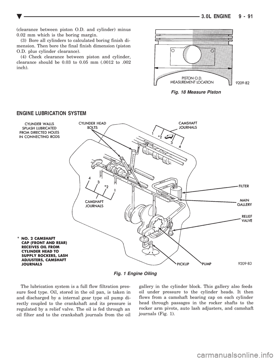
The lubrication system is a full flow filtration pres-
sure feed type. Oil, stored in the oil pan, is taken in
and discharged by a internal gear type oil pump di-
rectly coupled to the crankshaft and its pressure is
regulated by a relief valve. The oil is fed through an
oil filter and to the crankshaft journals from the oil gallery in the cylinder block. This gallery also feeds
oil under pressure to the cylinder heads. It then
flows from a camshaft bearing cap on each cylinder
head through passages in the rocker shafts to the
rocker arm pivots, auto lash adjusters, and camshaft
journals (Fig. 1).
Fig. 18 Measure Piston
Fig. 1 Engine Oiling
Ä 3.0L ENGINE 9 - 91
Page 1660 of 2438

OIL FILTER AND BRACKET
BRACKET INSPECTION
(1) Check the oil filter mounting surface. The sur-
face must be smooth, flat and free of debris or old
pieces of rubber (Fig. 12). (2) Check bracket for cracks and oil leaks.
OIL FILTER
CAUTION: When servicing the oil filter (Fig. 16)
avoid deforming the filter can by installing the re-
move/install tool band strap against the can-to-base
lockseam. The lockseam joining the can to the base
is reinforced by the base plate.
(1) Turn counter clockwise to remove.
(2) To install, lubricate new filter gasket. Screw
filter on until gasket contacts base. Tighten 1 turn.
Fig. 12 Oil Filter and Bracket
9 - 94 3.0L ENGINE Ä
Page 1664 of 2438
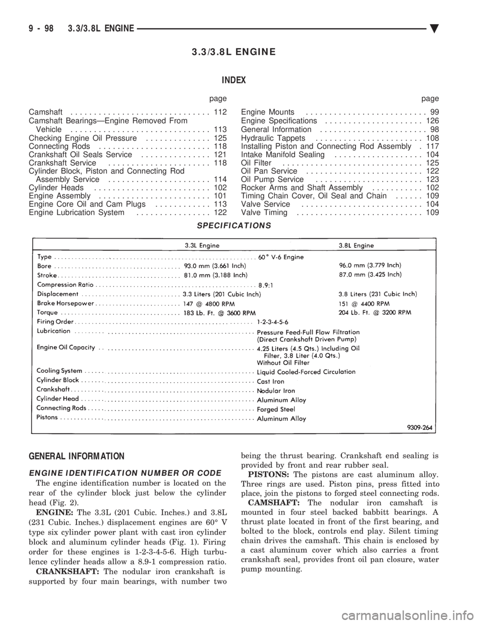
3.3/3.8L ENGINE INDEX
page page
Camshaft .............................. 112
Camshaft BearingsÐEngine Removed From Vehicle .............................. 113
Checking Engine Oil Pressure .............. 125
Connecting Rods ........................ 118
Crankshaft Oil Seals Service ............... 121
Crankshaft Service ...................... 118
Cylinder Block, Piston and Connecting Rod Assembly Service ...................... 114
Cylinder Heads ......................... 102
Engine Assembly ........................ 101
Engine Core Oil and Cam Plugs ............ 113
Engine Lubrication System ................ 122 Engine Mounts
.......................... 99
Engine Specifications ..................... 126
General Information ....................... 98
Hydraulic Tappets ....................... 108
Installing Piston and Connecting Rod Assembly . 117
Intake Manifold Sealing ................... 104
Oil Filter .............................. 125
Oil Pan Service ......................... 122
Oil Pump Service ....................... 123
Rocker Arms and Shaft Assembly ........... 102
Timing Chain Cover, Oil Seal and Chain ...... 109
Valve Service .......................... 104
Valve Timing ........................... 109
GENERAL INFORMATION
ENGINE IDENTIFICATION NUMBER OR CODE
The engine identification number is located on the
rear of the cylinder block just below the cylinder
head (Fig. 2). ENGINE: The 3.3L (201 Cubic. Inches.) and 3.8L
(231 Cubic. Inches.) displacement engines are 60É V
type six cylinder power plant with cast iron cylinder
block and aluminum cylinder heads (Fig. 1). Firing
order for these engines is 1-2-3-4-5-6. High turbu-
lence cylinder heads allow a 8.9-1 compression ratio. CRANKSHAFT: The nodular iron crankshaft is
supported by four main bearings, with number two being the thrust bearing. Crankshaft end sealing is
provided by front and rear rubber seal. PISTONS: The pistons are cast aluminum alloy.
Three rings are used. Piston pins, press fitted into
place, join the pistons to forged steel connecting rods. CAMSHAFT: The nodular iron camshaft is
mounted in four steel backed babbitt bearings. A
thrust plate located in front of the first bearing, and
bolted to the block, controls end play. Silent timing
chain drives the camshaft. This chain is enclosed by
a cast aluminum cover which also carries a front
crankshaft seal, provides front oil pan closure, water
pump mounting.
SPECIFICATIONS
9 - 98 3.3/3.8L ENGINE Ä
Page 1688 of 2438
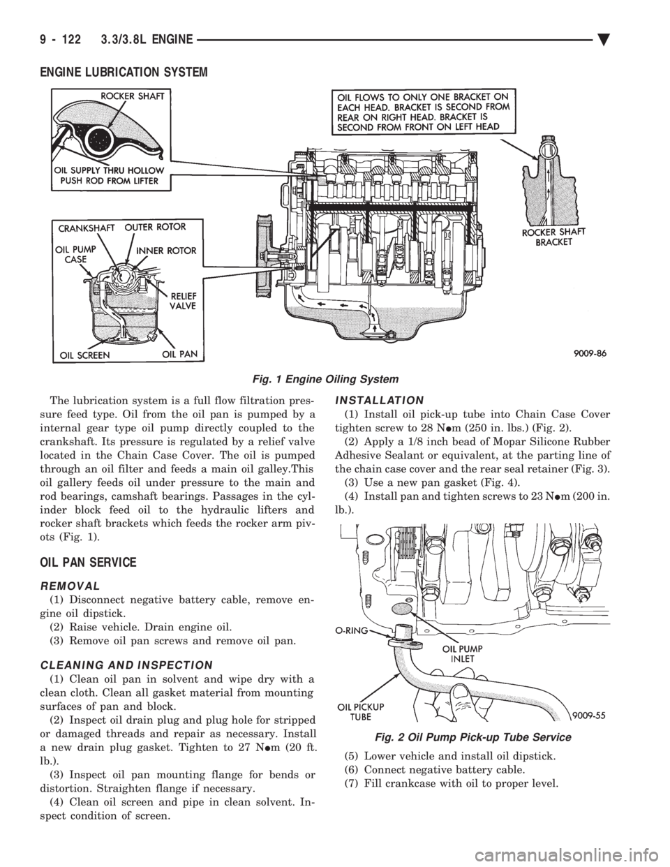
ENGINE LUBRICATION SYSTEM
The lubrication system is a full flow filtration pres-
sure feed type. Oil from the oil pan is pumped by a
internal gear type oil pump directly coupled to the
crankshaft. Its pressure is regulated by a relief valve
located in the Chain Case Cover. The oil is pumped
through an oil filter and feeds a main oil galley.This
oil gallery feeds oil under pressure to the main and
rod bearings, camshaft bearings. Passages in the cyl-
inder block feed oil to the hydraulic lifters and
rocker shaft brackets which feeds the rocker arm piv-
ots (Fig. 1).
OIL PAN SERVICE
REMOVAL
(1) Disconnect negative battery cable, remove en-
gine oil dipstick. (2) Raise vehicle. Drain engine oil.
(3) Remove oil pan screws and remove oil pan.
CLEANING AND INSPECTION
(1) Clean oil pan in solvent and wipe dry with a
clean cloth. Clean all gasket material from mounting
surfaces of pan and block. (2) Inspect oil drain plug and plug hole for stripped
or damaged threads and repair as necessary. Install
a new drain plug gasket. Tighten to 27 N Im (20 ft.
lb.). (3) Inspect oil pan mounting flange for bends or
distortion. Straighten flange if necessary. (4) Clean oil screen and pipe in clean solvent. In-
spect condition of screen.
INSTALLATION
(1) Install oil pick-up tube into Chain Case Cover
tighten screw to 28 N Im (250 in. lbs.) (Fig. 2).
(2) Apply a 1/8 inch bead of Mopar Silicone Rubber
Adhesive Sealant or equivalent, at the parting line of
the chain case cover and the rear seal retainer (Fig. 3). (3) Use a new pan gasket (Fig. 4).
(4) Install pan and tighten screws to 23 N Im (200 in.
lb.).
(5) Lower vehicle and install oil dipstick.
(6) Connect negative battery cable.
(7) Fill crankcase with oil to proper level.
Fig. 1 Engine Oiling System
Fig. 2 Oil Pump Pick-up Tube Service
9 - 122 3.3/3.8L ENGINE Ä
Page 1691 of 2438
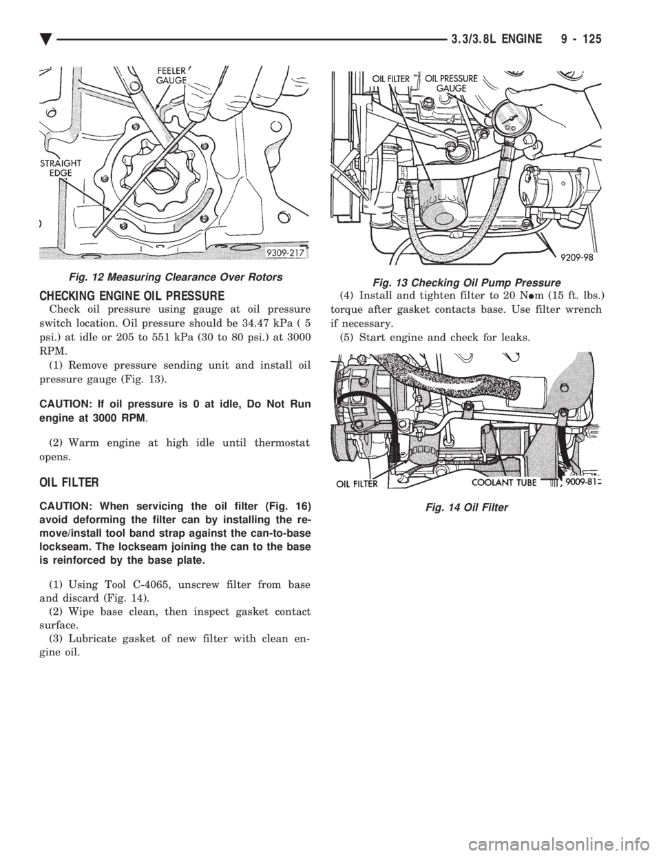
CHECKING ENGINE OIL PRESSURE
Check oil pressure using gauge at oil pressure
switch location. Oil pressure should be 34.47 kPa ( 5
psi.) at idle or 205 to 551 kPa (30 to 80 psi.) at 3000
RPM. (1) Remove pressure sending unit and install oil
pressure gauge (Fig. 13).
CAUTION: If oil pressure is 0 at idle, Do Not Run
engine at 3000 RPM .
(2) Warm engine at high idle until thermostat
opens.
OIL FILTER
CAUTION: When servicing the oil filter (Fig. 16)
avoid deforming the filter can by installing the re-
move/install tool band strap against the can-to-base
lockseam. The lockseam joining the can to the base
is reinforced by the base plate.
(1) Using Tool C-4065, unscrew filter from base
and discard (Fig. 14). (2) Wipe base clean, then inspect gasket contact
surface. (3) Lubricate gasket of new filter with clean en-
gine oil. (4) Install and tighten filter to 20 N
Im (15 ft. lbs.)
torque after gasket contacts base. Use filter wrench
if necessary. (5) Start engine and check for leaks.
Fig. 12 Measuring Clearance Over RotorsFig. 13 Checking Oil Pump Pressure
Fig. 14 Oil Filter
Ä 3.3/3.8L ENGINE 9 - 125
Page 1705 of 2438
EXHAUST MANIFOLD
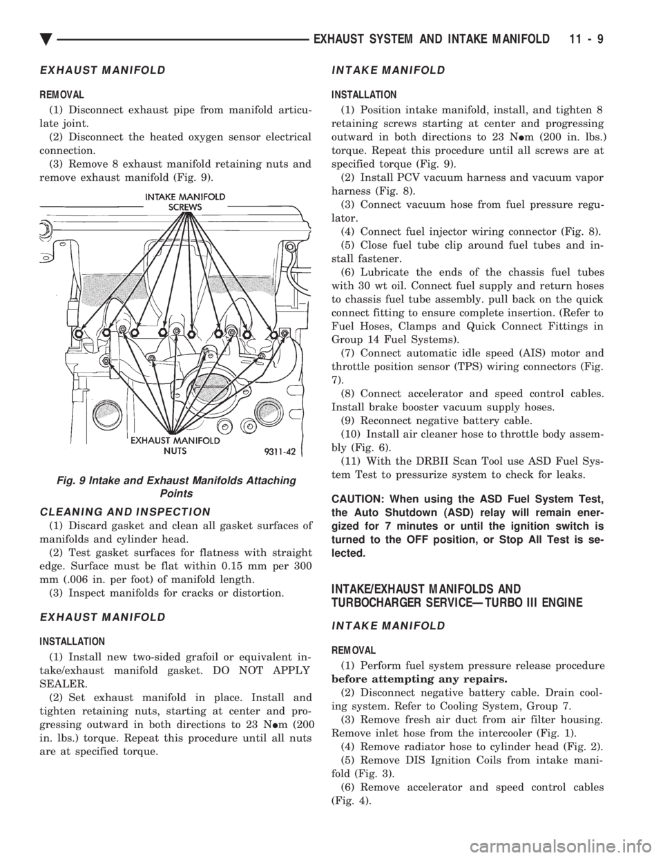
REMOVAL (1) Disconnect exhaust pipe from manifold articu-
late joint. (2) Disconnect the heated oxygen sensor electrical
connection. (3) Remove 8 exhaust manifold retaining nuts and
remove exhaust manifold (Fig. 9).
CLEANING AND INSPECTION
(1) Discard gasket and clean all gasket surfaces of
manifolds and cylinder head. (2) Test gasket surfaces for flatness with straight
edge. Surface must be flat within 0.15 mm per 300
mm (.006 in. per foot) of manifold length. (3) Inspect manifolds for cracks or distortion.
EXHAUST MANIFOLD
INSTALLATION
(1) Install new two-sided grafoil or equivalent in-
take/exhaust manifold gasket. DO NOT APPLY
SEALER. (2) Set exhaust manifold in place. Install and
tighten retaining nuts, starting at center and pro-
gressing outward in both directions to 23 N Im (200
in. lbs.) torque. Repeat this procedure until all nuts
are at specified torque.
INTAKE MANIFOLD
INSTALLATION
(1) Position intake manifold, install, and tighten 8
retaining screws starting at center and progressing
outward in both directions to 23 N Im (200 in. lbs.)
torque. Repeat this procedure until all screws are at
specified torque (Fig. 9). (2) Install PCV vacuum harness and vacuum vapor
harness (Fig. 8). (3) Connect vacuum hose from fuel pressure regu-
lator. (4) Connect fuel injector wiring connector (Fig. 8).
(5) Close fuel tube clip around fuel tubes and in-
stall fastener. (6) Lubricate the ends of the chassis fuel tubes
with 30 wt oil. Connect fuel supply and return hoses
to chassis fuel tube assembly. pull back on the quick
connect fitting to ensure complete insertion. (Refer to
Fuel Hoses, Clamps and Quick Connect Fittings in
Group 14 Fuel Systems). (7) Connect automatic idle speed (AIS) motor and
throttle position sensor (TPS) wiring connectors (Fig.
7). (8) Connect accelerator and speed control cables.
Install brake booster vacuum supply hoses. (9) Reconnect negative battery cable.
(10) Install air cleaner hose to throttle body assem-
bly (Fig. 6). (11) With the DRBII Scan Tool use ASD Fuel Sys-
tem Test to pressurize system to check for leaks.
CAUTION: When using the ASD Fuel System Test,
the Auto Shutdown (ASD) relay will remain ener-
gized for 7 minutes or until the ignition switch is
turned to the OFF position, or Stop All Test is se-
lected.
INTAKE/EXHAUST MANIFOLDS AND
TURBOCHARGER SERVICEÐTURBO III ENGINE
INTAKE MANIFOLD
REMOVAL
(1) Perform fuel system pressure release procedure
before attempting any repairs. (2) Disconnect negative battery cable. Drain cool-
ing system. Refer to Cooling System, Group 7. (3) Remove fresh air duct from air filter housing.
Remove inlet hose from the intercooler (Fig. 1). (4) Remove radiator hose to cylinder head (Fig. 2).
(5) Remove DIS Ignition Coils from intake mani-
fold (Fig. 3). (6) Remove accelerator and speed control cables
(Fig. 4).
Fig. 9 Intake and Exhaust Manifolds Attaching Points
Ä EXHAUST SYSTEM AND INTAKE MANIFOLD 11 - 9
Page 1707 of 2438
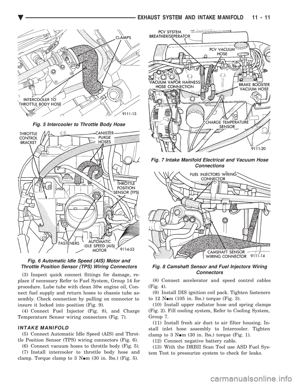
(3) Inspect quick connect fittings for damage, re-
place if necessary Refer to Fuel System, Group 14 for
procedure. Lube tube with clean 30w engine oil, Con-
nect fuel supply and return hoses to chassis tube as-
sembly. Check connection by pulling on connector to
insure it locked into position (Fig. 9). (4) Connect Fuel Injector (Fig. 8), and Charge
Temperature Sensor wiring connectors (Fig. 7).
INTAKE MANIFOLD
(5) Connect Automatic Idle Speed (AIS) and Throt-
tle Position Sensor (TPS) wiring connectors (Fig. 6). (6) Connect vacuum hoses to throttle body (Fig. 5).
(7) Install intercooler to throttle body hose and
clamp. Torque clamp to 3 N Im (30 in. lbs.) (Fig. 5). (8) Connect accelerator and speed control cables
(Fig. 4). (9) Install DIS ignition coil pack. Tighten fasteners
to 12 N Im (105 in. lbs.) torque (Fig. 3).
(10) Install upper radiator hose and spring clamps
(Fig. 2). Fill cooling system, Refer to Cooling System,
Group 7. (11) Install fresh air duct to air filter housing. In-
stall inlet hose assembly to Intercooler. Tighten
clamp to 3 N Im (30 in. lbs.) torque (Fig. 1).
(12) Connect negative battery cable.
(13) With the DRBII Scan Tool use ASD Fuel Sys-
tem Test to pressurize system to check for leaks.
Fig. 5 Intercooler to Throttle Body Hose
Fig. 6 Automatic Idle Speed (AIS) Motor and
Throttle Position Sensor (TPS) Wiring Connectors
Fig. 7 Intake Manifold Electrical and Vacuum Hose Connections
Fig. 8 Camshaft Sensor and Fuel Injectors WiringConnectors
Ä EXHAUST SYSTEM AND INTAKE MANIFOLD 11 - 11