maintenance CHEVROLET DYNASTY 1993 Workshop Manual
[x] Cancel search | Manufacturer: CHEVROLET, Model Year: 1993, Model line: DYNASTY, Model: CHEVROLET DYNASTY 1993Pages: 2438, PDF Size: 74.98 MB
Page 1576 of 2438
shaft end play. A sintered iron (TBI engine and steel
billet Turbo III engines) timing belt sprocket is
mounted on the cam nose, and a hydrodynamic oil
seal is used for oil control at the front of the cam-
shaft. ACCESSORY SHAFT: The iron accessory shaft
has two bearing journals and is housed in the for-
ward facing side of the block. A hydrodynamic seal,
installed in an aluminum housing attached to the
block, provides retention, shaft thrust, and oil con-
trol. The accessory shaft is driven by the timing belt
through a sintered iron (TBI engine and steel billet
Turbo III engines) sprocket mounted on the nose of
the accessory shaft. The accessory shaft in turn
drives the oil pump and distributor on 2.2/2.5L and
2.5L FFV and the oil pump only on Turbo III. VALVES: The valves are actuated by roller cam
followers which pivot on stationary hydraulic lash
adjusters. The valve train with 40.6 mm (1.60 inch)
diameter intake valves and 35.4 mm (1.39 inch) di-
ameter exhaust valves employ viton rubber valve
stem seals except 2.5L FFv . the 2.5L FFV valve
stem seals are made of special rubber compound
which resist the deteriorating effects of methanol
fuel by-products that enter the oil during combus-
tion. Valve springs, spring retainers, and locks are
conventional. For Turbo III engines the valves are
actuated by roller tipped rocker arms with hydraulic
lash adjusters which pivot on a shaft. The valve train
with 33.88 mm (1.33 in.) diameter intake valves are
arranged in line opposite of the 29.26 mm (1.15 in.)
diameter exhaust valves employ locking valve stem
seals. Valve springs, spring retainers, and locks are
not interchangeable with other engines. BALANCE SHAFTS: 2.2 Turbo III and 2.5L en-
gines are equipped with two counter rotating balance
shafts installed in a carrier attached to the lower
crankcase. The shafts are interconnect through
gears. These gears are driven by a short chain from
the crankshaft, to rotate at two times crankshaft
speed. This counterbalances certain engine recipro-
cating forces. INTAKE MANIFOLDS:
All intake manifolds are
aluminum castings, attached to the cylinder head
with eight bolts. N.A. engines use a four branch de-
sign. This long branch fan design enhances low and
midspeed torque. It also features an integrally cast
water crossover passage to warm incoming fuel/air
mixture, plus an EGR mounting boss and PCV inlet. The Turbo III engine intake manifold is a log type
with tuned runners. The manifold is machined to ac-
cept fuel injectors near the ports of each cylinder. EXHAUST MANIFOLDS: The exhaust manifolds
are made of nodular cast iron for strength and high
temperatures. All naturally aspirated (N.A.) and tur-
bocharged engines exit exhaust gasses through a ma-
chined, articulated joint connection to the exhaust
pipe. 2.2/2.5L and 2.5L FFV manifolds intermesh
with the intake manifold at the cylinder head. N.A. engines use a four branch design with cylin-
ders one and four joined and cylinder two and three
joined to exit at the outlet. The Turbo III engine exhaust manifold also carries
the turbocharger. This manifold has a modified log
type collector with exhaust gasses directed to and
through the turbocharger to exit the conical (articu-
lated joint) outlet machined into the turbocharger ex-
haust elbow. ENGINE LUBRICATION: Refer to Group 0 Lu-
brication and Maintenance for recommended oil to be
used in various engine application. System is full
flow filtration, pressure feed type. The oil pump is
mounted within the crankcase and driven by the ac-
cessory shaft. Pressurized oil is then routed through
the main oil gallery, running the length of the cylin-
der block, supplying main and rod bearings with fur-
ther routing (for 2.2L turbo III and 2.5L engines) to
the lower balance shaft assemblies. Pistons are lubri-
cated from directed holes in the connecting rod as-
semblies. Camshaft and valve mechanisms are
lubricated from a full-length cylinder head oil gallery
supplied from the crankcase main oil gallery.
9 - 10 2.2/2.5L ENGINE Ä
Page 1697 of 2438
EXHAUST SYSTEM AND INTAKE MANIFOLD
CONTENTS
page page
GENERAL INFORMATION .................. 1
SERVICE PROCEDURES ................... 4 TORQUE SPECIFICATION
................. 25
GENERAL INFORMATION
Throughout this group, references may be made to
a particular vehicle by letter or number designation.
A chart showing the breakdown of these designations
is included in the Introduction Section at the front of
this service manual.
EXHAUST SYSTEMS
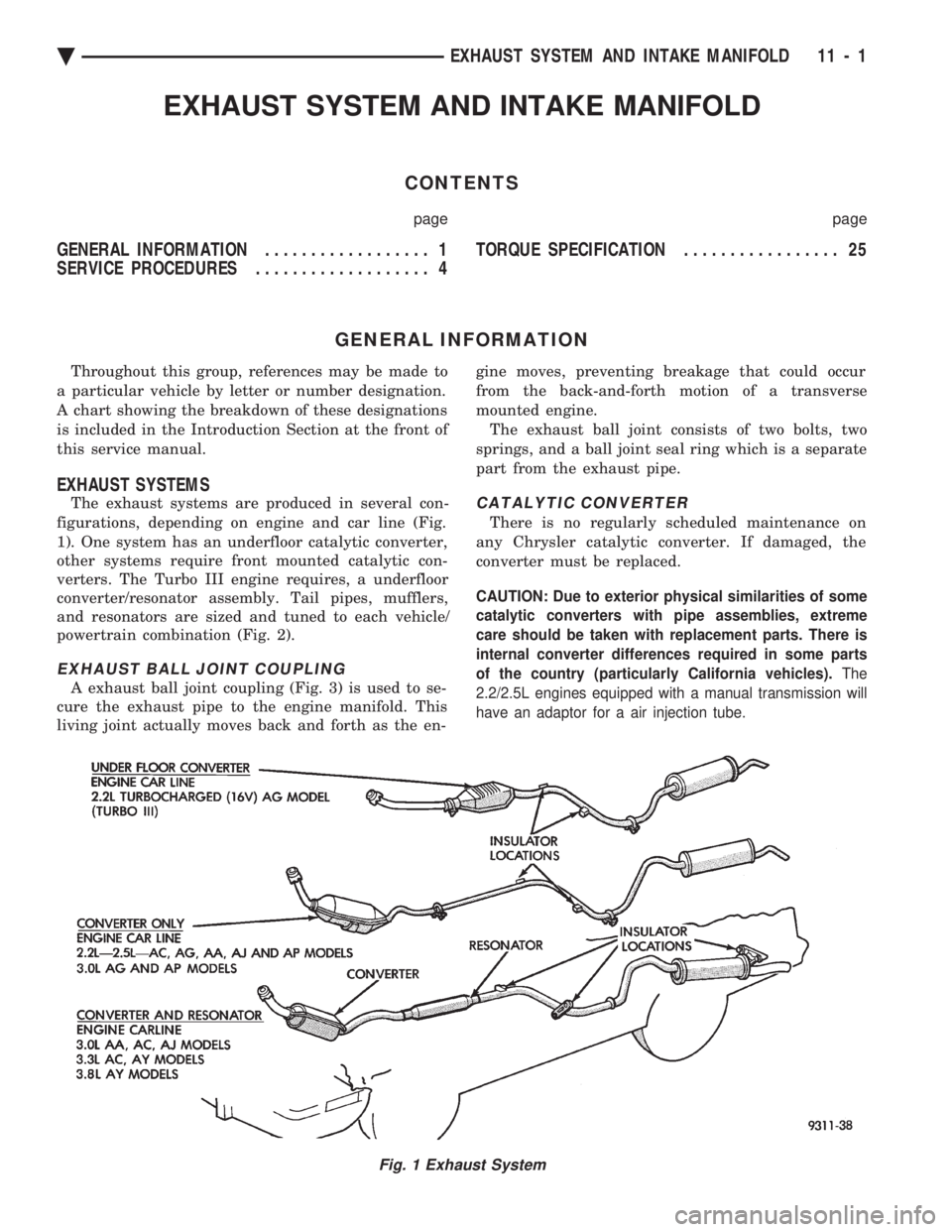
The exhaust systems are produced in several con-
figurations, depending on engine and car line (Fig.
1). One system has an underfloor catalytic converter,
other systems require front mounted catalytic con-
verters. The Turbo III engine requires, a underfloor
converter/resonator assembly. Tail pipes, mufflers,
and resonators are sized and tuned to each vehicle/
powertrain combination (Fig. 2).
EXHAUST BALL JOINT COUPLING
A exhaust ball joint coupling (Fig. 3) is used to se-
cure the exhaust pipe to the engine manifold. This
living joint actually moves back and forth as the en- gine moves, preventing breakage that could occur
from the back-and-forth motion of a transverse
mounted engine. The exhaust ball joint consists of two bolts, two
springs, and a ball joint seal ring which is a separate
part from the exhaust pipe.
CATALYTIC CONVERTER
There is no regularly scheduled maintenance on
any Chrysler catalytic converter. If damaged, the
converter must be replaced.
CAUTION: Due to exterior physical similarities of some
catalytic converters with pipe assemblies, extreme
care should be taken with replacement parts. There is
internal converter differences required in some parts
of the country (particularly California vehicles). The
2.2/2.5L engines equipped with a manual transmission will
have an adaptor for a air injection tube.
Fig. 1 Exhaust System
Ä EXHAUST SYSTEM AND INTAKE MANIFOLD 11 - 1
Page 1739 of 2438
CROSSMEMBER
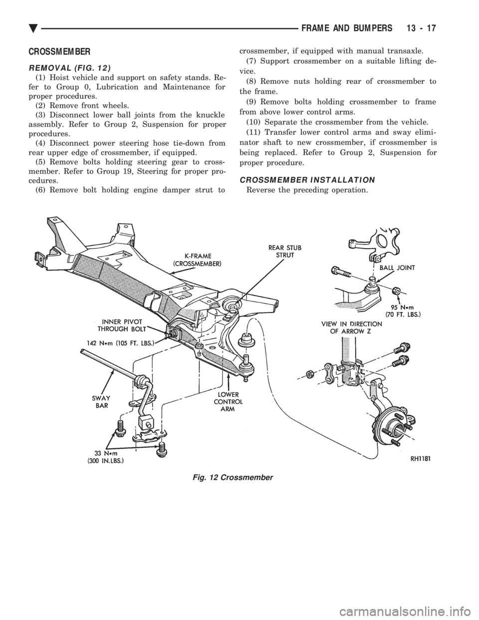
REMOVAL (FIG. 12)
(1) Hoist vehicle and support on safety stands. Re-
fer to Group 0, Lubrication and Maintenance for
proper procedures. (2) Remove front wheels.
(3) Disconnect lower ball joints from the knuckle
assembly. Refer to Group 2, Suspension for proper
procedures. (4) Disconnect power steering hose tie-down from
rear upper edge of crossmember, if equipped. (5) Remove bolts holding steering gear to cross-
member. Refer to Group 19, Steering for proper pro-
cedures. (6) Remove bolt holding engine damper strut to crossmember, if equipped with manual transaxle.
(7) Support crossmember on a suitable lifting de-
vice. (8) Remove nuts holding rear of crossmember to
the frame. (9) Remove bolts holding crossmember to frame
from above lower control arms. (10) Separate the crossmember from the vehicle.
(11) Transfer lower control arms and sway elimi-
nator shaft to new crossmember, if crossmember is
being replaced. Refer to Group 2, Suspension for
proper procedure.
CROSSMEMBER INSTALLATION
Reverse the preceding operation.
Fig. 12 Crossmember
Ä FRAME AND BUMPERS 13 - 17
Page 2158 of 2438
BODY DIAGNOSTIC PROCEDURES INDEX
page page
Water Leaks ............................. 2 Wind Noise.............................. 3
WATER LEAKS
Water leaks can be caused by poor sealing, improper
body component alignment, body seam porosity, miss-
ing plugs, or blocked drain holes. Centrifugal and
gravitational force can cause water to drip from an
area somewhat distant from the actual leak point,
making leak detection difficult. All body sealing points
should be water tight in normal wet driving conditions.
Water flowing downward from the front of the vehicle
should not enter the passenger or luggage compart-
ment. Moving sealing surfaces will not always seal
water tight under all conditions. At times, side glass,
door, or convertible top seals will allow water to enter
the passenger compartment during high pressure
washing or hard driving rain (severe) conditions. Over
compensating on door, glass, or top adjustments to stop
a water leak that occurs under severe conditions, can
cause premature seal wear and excessive closing or
latching effort. After a repair procedure has been
performed, water test vehicle to verify leak has stopped
before returning vehicle to use.
VISUAL INSPECTION BEFORE WATER LEAK TESTS
Verify that floor and body plugs are in place, body
drains are clear and body components are aligned and
sealed. If component alignment or sealing is necessary,
refer to the appropriate section of this group for proper
procedures.
WATER LEAK TESTS
WARNING: DO NOT USE ELECTRIC SHOP LIGHTS
OR TOOLS IN WATER TEST AREA, PERSONAL IN-
JURY CAN RESULT.
When a determination has been made on the condi-
tions that a water leak occurs, simulate the conditions
as closely as possible.
² If a leak occurs when the car is parked in a steady
light rain, flood the leak area with a open ended garden
hose.
² If a leak occurs at highway speeds in a steady rain,
test the leak area with a stream or fan spray of water
from a garden hose with an adjustable nozzle. Direct
the spray in the direction comparable to actual condi-
tions. ²
If a leak seems to occur only when the vehicle is
parked on an incline, hoist the end or side of the vehicle
to simulate this condition before water testing. This
method can also be used when the leak occurs when the
vehicle accelerates, stops, or turns. If the leak occurs
on acceleration, hoist the front of the vehicle. If the
leak occurs when braking, hoist the back of the vehicle.
If the leak occurs on left turns, hoist the left side of the
vehicle. If the leak occurs on right turns, hoist the right
side of the vehicle. For hoisting recommendations refer
to Group 0, Lubrication and Maintenance, General
Information section.
WATER LEAK DETECTION
To detect a water leak point of entry, perform a water
test and watch for water tracks or droplets forming on
the inside if the vehicle. If necessary remove interior
trim covers or panels to gain visual access to the leak
area. If the hose can not be positioned without being
held, have someone help perform the water test. Some water leaks must be tested for a considerable
length of time to become apparent. When a leak ap-
pears, determine the highest point of the water track or
drop. The highest point usually will indicate the point
of entry. After leak point has been determined, repair
the leak and water test to verify that leak has stopped. Locating the entry point of water that is leaking into
a cavity between panels can be difficult. The trapped
water splashes or runs from the cavity it is dammed up
in, often at a distance from the entry point. Most water
leaks of this type become apparent after accelerating,
stopping, turning, or when on a incline.
MIRROR INSPECTION METHOD
When a leak point area is visually obstructed, use a
suitable mirror to gain visual access. A mirror can also
be used to deflect light to a limited access area to assist
in locating a leak point.
BRIGHT LIGHT LEAK TEST METHOD
Some water leaks in the luggage compartment can be
detected without water testing. Position the vehicle in
a brightly light area. From inside the darkened lug-
gage compartment inspect around seals and body
seams. If necessary, have a helper direct a drop light
over the suspected leak areas around the lug-
23 - 2 BODY Ä
Page 2401 of 2438
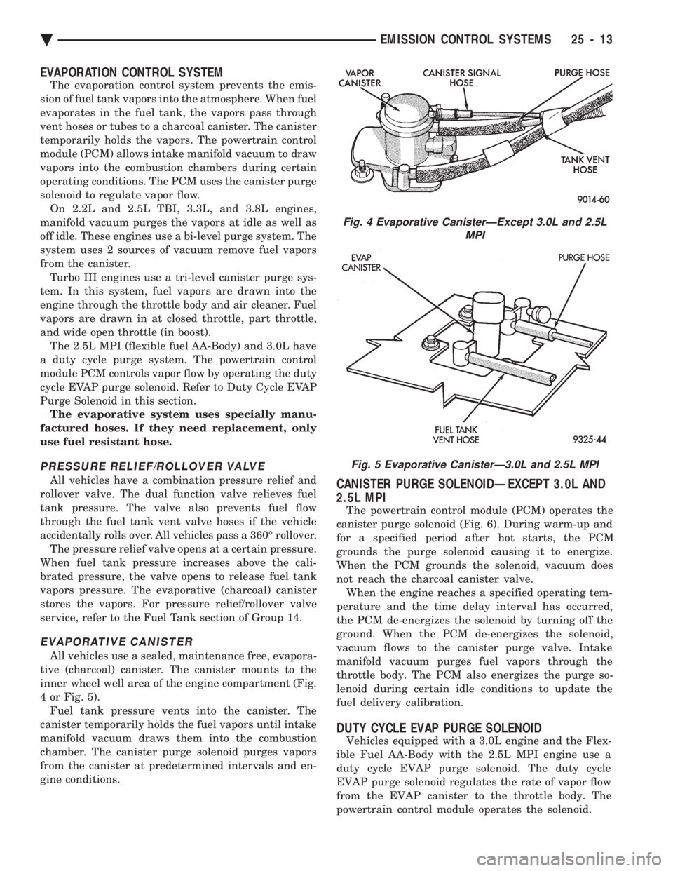
EVAPORATION CONTROL SYSTEM
The evaporation control system prevents the emis-
sion of fuel tank vapors into the atmosphere. When fuel
evaporates in the fuel tank, the vapors pass through
vent hoses or tubes to a charcoal canister. The canister
temporarily holds the vapors. The powertrain control
module (PCM) allows intake manifold vacuum to draw
vapors into the combustion chambers during certain
operating conditions. The PCM uses the canister purge
solenoid to regulate vapor flow. On 2.2L and 2.5L TBI, 3.3L, and 3.8L engines,
manifold vacuum purges the vapors at idle as well as
off idle. These engines use a bi-level purge system. The
system uses 2 sources of vacuum remove fuel vapors
from the canister. Turbo III engines use a tri-level canister purge sys-
tem. In this system, fuel vapors are drawn into the
engine through the throttle body and air cleaner. Fuel
vapors are drawn in at closed throttle, part throttle,
and wide open throttle (in boost). The 2.5L MPI (flexible fuel AA-Body) and 3.0L have
a duty cycle purge system. The powertrain control
module PCM controls vapor flow by operating the duty
cycle EVAP purge solenoid. Refer to Duty Cycle EVAP
Purge Solenoid in this section. The evaporative system uses specially manu-
factured hoses. If they need replacement, only
use fuel resistant hose.
PRESSURE RELIEF/ROLLOVER VALVE
All vehicles have a combination pressure relief and
rollover valve. The dual function valve relieves fuel
tank pressure. The valve also prevents fuel flow
through the fuel tank vent valve hoses if the vehicle
accidentally rolls over. All vehicles pass a 360É rollover. The pressure relief valve opens at a certain pressure.
When fuel tank pressure increases above the cali-
brated pressure, the valve opens to release fuel tank
vapors pressure. The evaporative (charcoal) canister
stores the vapors. For pressure relief/rollover valve
service, refer to the Fuel Tank section of Group 14.
EVAPORATIVE CANISTER
All vehicles use a sealed, maintenance free, evapora-
tive (charcoal) canister. The canister mounts to the
inner wheel well area of the engine compartment (Fig.
4 or Fig. 5). Fuel tank pressure vents into the canister. The
canister temporarily holds the fuel vapors until intake
manifold vacuum draws them into the combustion
chamber. The canister purge solenoid purges vapors
from the canister at predetermined intervals and en-
gine conditions.
CANISTER PURGE SOLENOIDÐEXCEPT 3.0L AND
2.5L MPI
The powertrain control module (PCM) operates the
canister purge solenoid (Fig. 6). During warm-up and
for a specified period after hot starts, the PCM
grounds the purge solenoid causing it to energize.
When the PCM grounds the solenoid, vacuum does
not reach the charcoal canister valve. When the engine reaches a specified operating tem-
perature and the time delay interval has occurred,
the PCM de-energizes the solenoid by turning off the
ground. When the PCM de-energizes the solenoid,
vacuum flows to the canister purge valve. Intake
manifold vacuum purges fuel vapors through the
throttle body. The PCM also energizes the purge so-
lenoid during certain idle conditions to update the
fuel delivery calibration.
DUTY CYCLE EVAP PURGE SOLENOID
Vehicles equipped with a 3.0L engine and the Flex-
ible Fuel AA-Body with the 2.5L MPI engine use a
duty cycle EVAP purge solenoid. The duty cycle
EVAP purge solenoid regulates the rate of vapor flow
from the EVAP canister to the throttle body. The
powertrain control module operates the solenoid.
Fig. 4 Evaporative CanisterÐExcept 3.0L and 2.5L MPI
Fig. 5 Evaporative CanisterÐ3.0L and 2.5L MPI
Ä EMISSION CONTROL SYSTEMS 25 - 13
Page 2421 of 2438
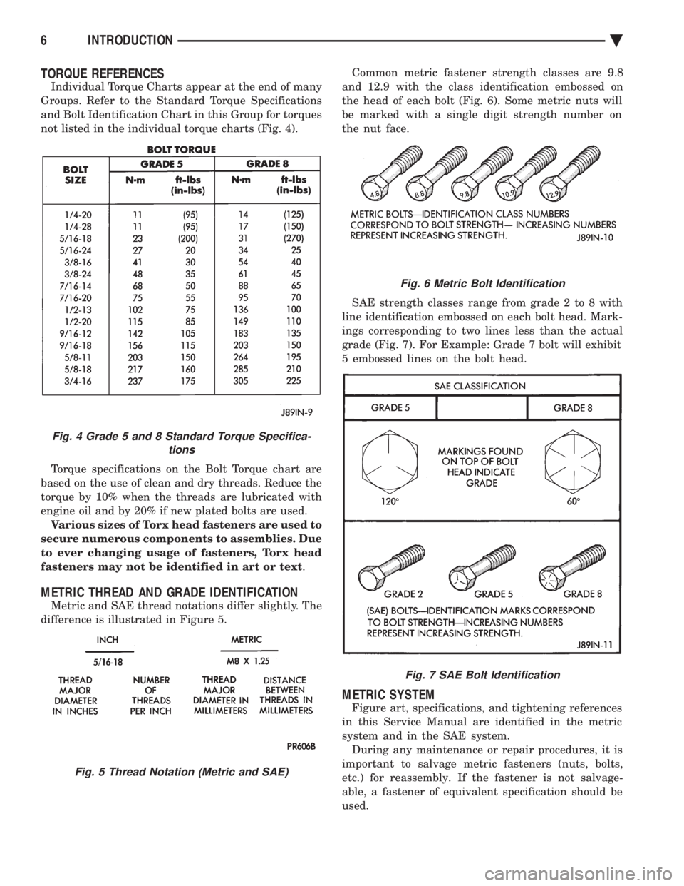
TORQUE REFERENCES
Individual Torque Charts appear at the end of many
Groups. Refer to the Standard Torque Specifications
and Bolt Identification Chart in this Group for torques
not listed in the individual torque charts (Fig. 4).
Torque specifications on the Bolt Torque chart are
based on the use of clean and dry threads. Reduce the
torque by 10% when the threads are lubricated with
engine oil and by 20% if new plated bolts are used. Various sizes of Torx head fasteners are used to
secure numerous components to assemblies. Due
to ever changing usage of fasteners, Torx head
fasteners may not be identified in art or text .
METRIC THREAD AND GRADE IDENTIFICATION
Metric and SAE thread notations differ slightly. The
difference is illustrated in Figure 5. Common metric fastener strength classes are 9.8
and 12.9 with the class identification embossed on
the head of each bolt (Fig. 6). Some metric nuts will
be marked with a single digit strength number on
the nut face.
SAE strength classes range from grade 2 to 8 with
line identification embossed on each bolt head. Mark-
ings corresponding to two lines less than the actual
grade (Fig. 7). For Example: Grade 7 bolt will exhibit
5 embossed lines on the bolt head.
METRIC SYSTEM
Figure art, specifications, and tightening references
in this Service Manual are identified in the metric
system and in the SAE system. During any maintenance or repair procedures, it is
important to salvage metric fasteners (nuts, bolts,
etc.) for reassembly. If the fastener is not salvage-
able, a fastener of equivalent specification should be
used.
Fig. 6 Metric Bolt Identification
Fig. 7 SAE Bolt Identification
Fig. 4 Grade 5 and 8 Standard Torque Specifica- tions
Fig. 5 Thread Notation (Metric and SAE)
6 INTRODUCTION Ä