display CHEVROLET DYNASTY 1993 Manual Online
[x] Cancel search | Manufacturer: CHEVROLET, Model Year: 1993, Model line: DYNASTY, Model: CHEVROLET DYNASTY 1993Pages: 2438, PDF Size: 74.98 MB
Page 2387 of 2438
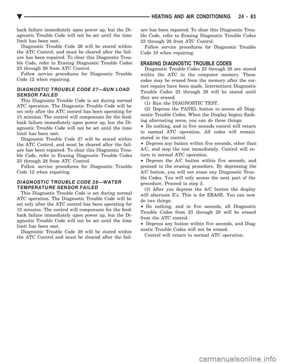
back failure immediately upon power up, but the Di-
agnostic Trouble Code will not be set until the time
limit has been met. Diagnostic Trouble Code 26 will be stored within
the ATC Control, and must be cleared after the fail-
ure has been repaired. To clear this Diagnostic Trou-
ble Code, refer to Erasing Diagnostic Trouble Codes
23 through 28 from ATC Control. Follow service procedures for Diagnostic Trouble
Code 12 when repairing.
DIAGNOSTIC TROUBLE CODE 27ÐSUN LOAD SENSOR FAILED
This Diagnostic Trouble Code is set during normal
ATC operation. The Diagnostic Trouble Code will be
set only after the ATC control has been operating for
15 minutes. The control will compensate for the feed-
back failure immediately upon power up, but the Di-
agnostic Trouble Code will not be set until the time
limit has been met. Diagnostic Trouble Code 27 will be stored within
the ATC Control, and must be cleared after the fail-
ure has been repaired. To clear this Diagnostic Trou-
ble Code, refer to Erasing Diagnostic Trouble Codes
23 through 28 from ATC Control. Follow service procedures for Diagnostic Trouble
Code 12 when repairing.
DIAGNOSTIC TROUBLE CODE 28ÐWATER TEMPERATURE SENSOR FAILED
This Diagnostic Trouble Code is set during normal
ATC operation. The Diagnostic Trouble Code will be
set only after the ATC control has been operating for
15 minutes. The control will compensate for the feed-
back failure immediately upon power up, but the Di-
agnostic Trouble Code will not be set until the time
limit has been met. Diagnostic Trouble Code 28 will be stored within
the ATC Control and must be cleared after the fail- ure has been repaired. To clear this Diagnostic Trou-
ble Code, refer to Erasing Diagnostic Trouble Codes
23 through 28 from ATC Control. Follow service procedures for Diagnostic Trouble
Code 10 when repairing.
ERASING DIAGNOSTIC TROUBLE CODES
Diagnostic Trouble Codes 23 through 28 are stored
within the ATC in the computer memory. These
codes may be erased from the memory after the cor-
rect repairs have been made. Intermittent Diagnostic
Trouble Codes 23 through 28 will be stored until
they are erased. (1) Run the DIAGNOSTIC TEST.
(2) Depress the PANEL button to access all Diag-
nostic Trouble Codes. When the Display begins flash-
ing alternating zeros, you can do three things:
² Do nothing, and in five seconds control will return
to normal ATC operation. All codes will remain
stored in the control.
² Depress any button within five seconds, other than
A/C, and stop the test immediately. Control will re-
turn to normal ATC operation.
² Depress the A/C button within five seconds, and
proceed to the erasing procedure. By depressing the
A/C button, you will not erase any Diagnostic Trou-
ble Codes. You will only access the next part of the
procedure. Proceed to step 3. (3) After you depress the A/C button the display
will alternate E's. This is for ERASE. You can now
do two things:
² Do nothing, and in five seconds, all Diagnostic
Trouble Codes from 23 through 28 will be erased
from the ATC control.
² Depress any button within five seconds, and Diag-
nostic Trouble Codes will not be erased. Control will return to normal ATC operation.
Ä HEATING AND AIR CONDITIONING 24 - 83
Page 2424 of 2438
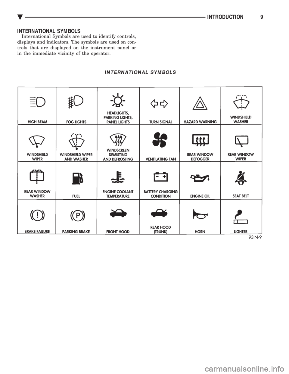
INTERNATIONAL SYMBOLS
International Symbols are used to identify controls,
displays and indicators. The symbols are used on con-
trols that are displayed on the instrument panel or
in the immediate vicinity of the operator.
INTERNATIONAL SYMBOLS
Ä INTRODUCTION9
Page 2432 of 2438
4
3.0 Using The CD-ROM
3.1 Welcome Page Of A Manual
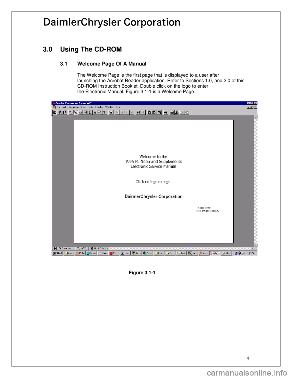
The Welcome Page is the first page that is displayed to a user after
launching the Acrobat Reader application. Refer to Sections 1.0, and 2.0 of this
CD-ROM Instruction Booklet. Double click on the logo to enter
the Electronic Manual. Figure 3.1-1 is a Welcome Page.
Figure 3.1-1
Page 2433 of 2438
Page 5
03/30/99
Rev. 0
3.2 Tab Page Of A Manual
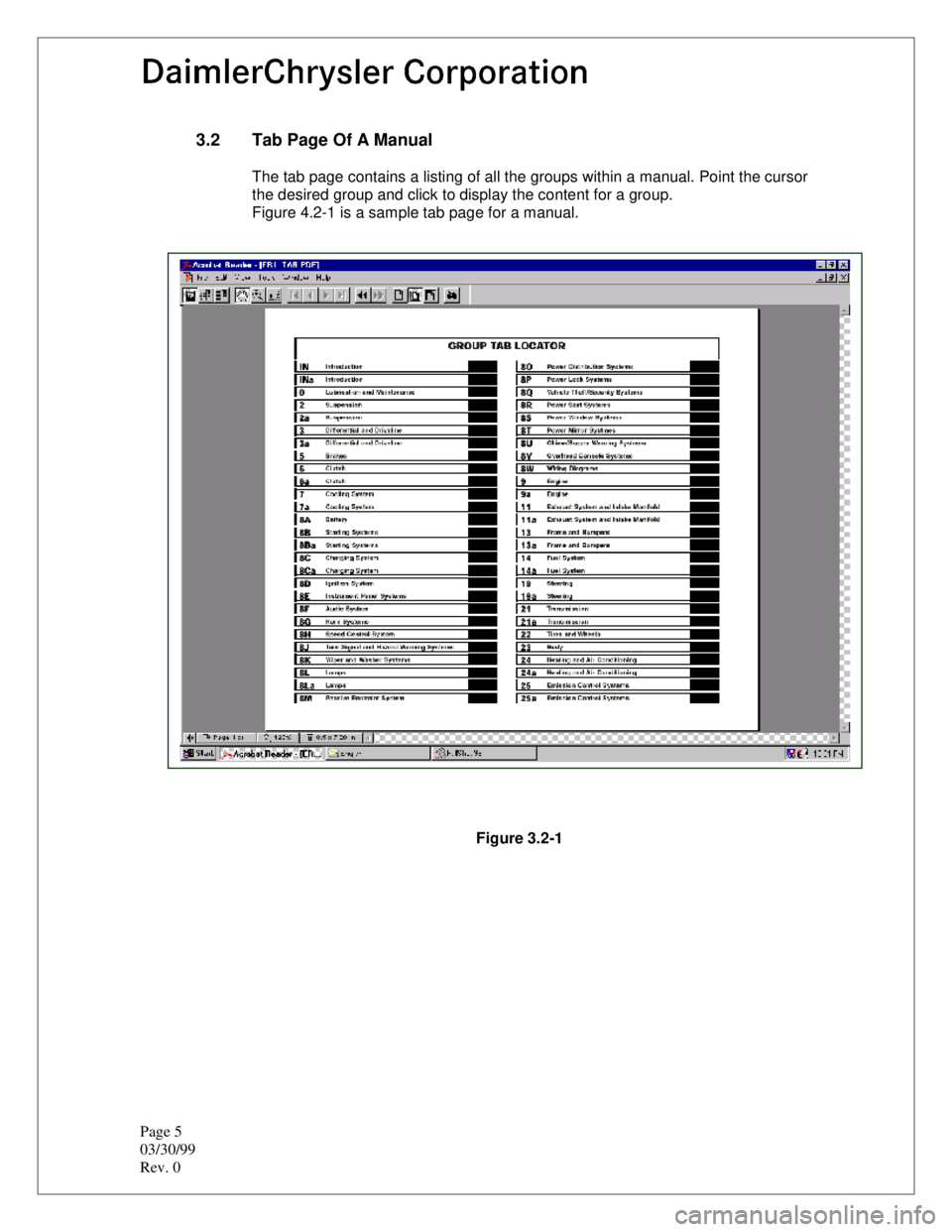
The tab page contains a listing of all the groups within a manual. Point the cursor
the desired group and click to display the content for a group.
Figure 4.2-1 is a sample tab page for a manual.
Figure 3.2-1
Page 2435 of 2438
Page 7
03/30/99
Rev. 0
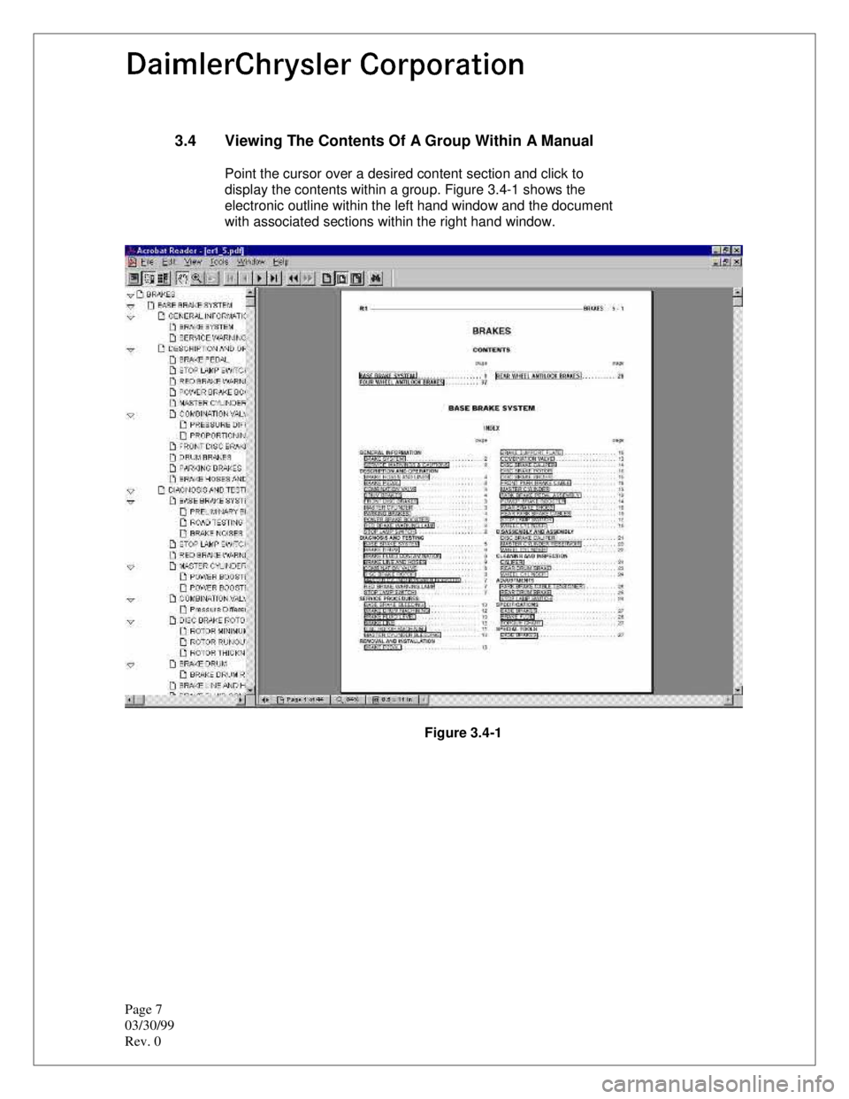
3.4 Viewing The Contents Of A Group Within A Manual
Point the cursor over a desired content section and click to
display the contents within a group. Figure 3.4-1 shows the
electronic outline within the left hand window and the document
with associated sections within the right hand window.
Figure 3.4-1
Page 2436 of 2438
8
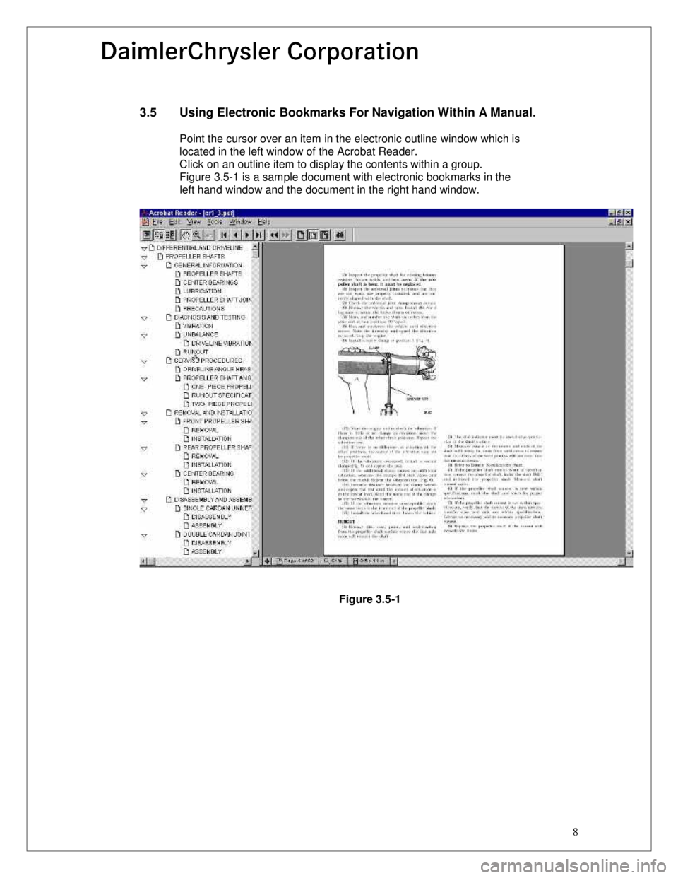
3.5 Using Electronic Bookmarks For Navigation Within A Manual.
Point the cursor over an item in the electronic outline window which is located in the left window of the Acrobat Reader.
Click on an outline item to display the contents within a group.
Figure 3.5-1 is a sample document with electronic bookmarks in the
left hand window and the document in the right hand window.
Figure 3.5-1
Page 2437 of 2438
Page 9
03/30/99
Rev. 0
4.0 Using The Acrobat Reader
4.1 Acrobat Reader On-Line Help
The complete user help file can be accessed by selecting the
Help Menu option and then Reader Online Guide option within
the Acrobat Reader application.
4.2 Summary Of Acrobat Reader Toolbar Features
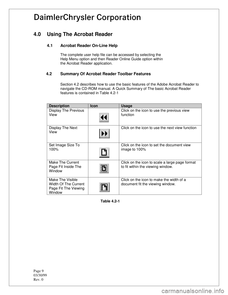
Section 4.2 describes how to use the basic features of the Adobe Acrobat Reader to
navigate the CD-ROM manual. A Quick Summary of The basic Acrobat Reader
features is contained in Table 4.2-1
DescriptionIconUsage
Display The Previous
View Click on the icon to use the previous view
function
Display The Next
View Click on the icon to use the next view function
Set Image Size To
100% Click on the icon to set the document view
image to 100%
Make The Current
Page Fit Inside The
Window Click on the icon to scale a large page format
to fit within the viewing window.
Make The Visible
Width Of The Current
Page Fit The Viewing
Window Click on the icon to make the width of a
document fit the viewing window.
Table 4.2-1
Page 2438 of 2438
10
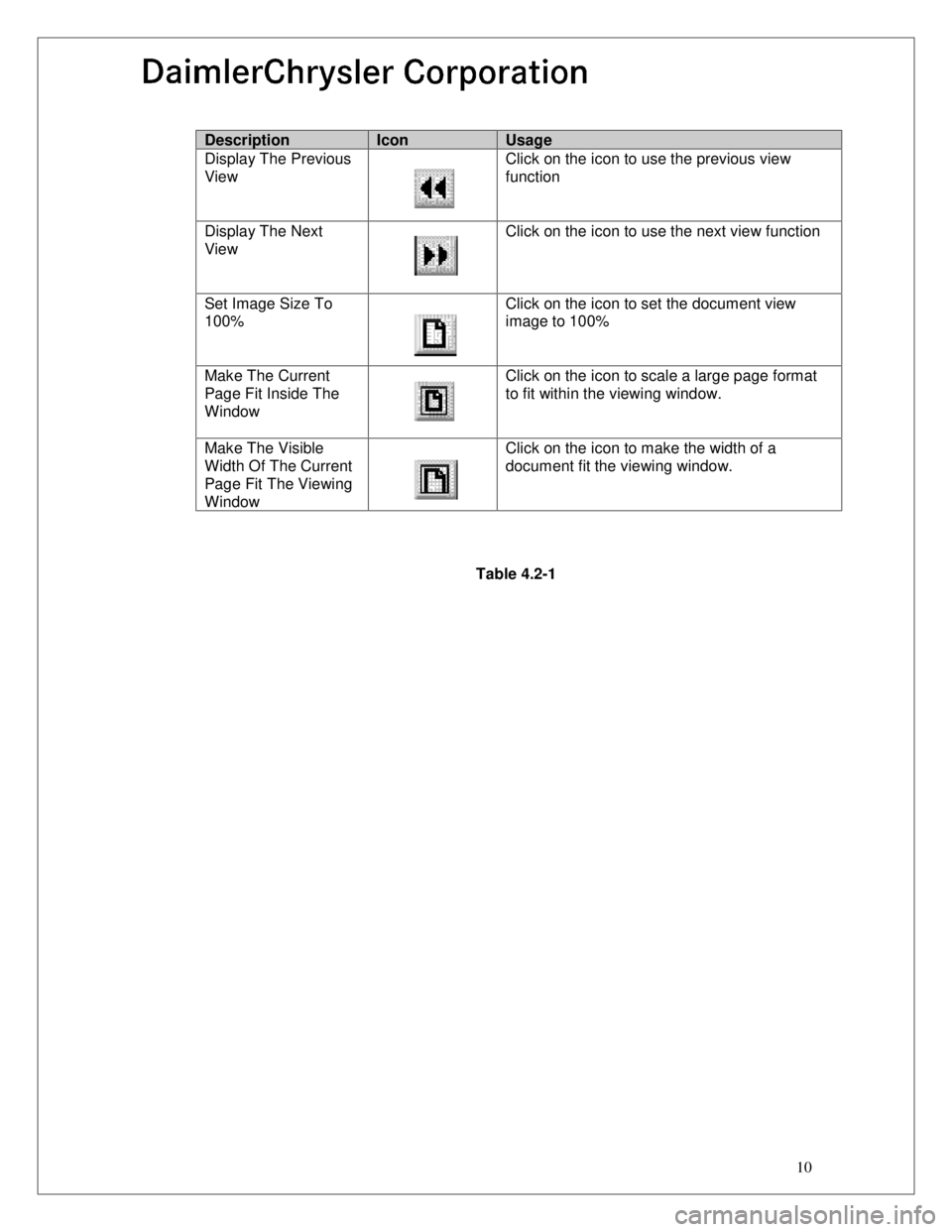
DescriptionIconUsage
Display The Previous
View Click on the icon to use the previous view
function
Display The Next
View Click on the icon to use the next view function
Set Image Size To
100% Click on the icon to set the document view
image to 100%
Make The Current
Page Fit Inside The
Window Click on the icon to scale a large page format
to fit within the viewing window.
Make The Visible
Width Of The Current
Page Fit The Viewing
Window Click on the icon to make the width of a
document fit the viewing window.
Table 4.2-1