display CHEVROLET DYNASTY 1993 Service Manual
[x] Cancel search | Manufacturer: CHEVROLET, Model Year: 1993, Model line: DYNASTY, Model: CHEVROLET DYNASTY 1993Pages: 2438, PDF Size: 74.98 MB
Page 123 of 2438
REAR LEVELING DIAGNOSTIC PROCEDURES
SELF-DIAGNOSTICS
A self-diagnostic procedure is available for the ser-
vice technician to use to detect system malfunctions.
BEFORE DIAGNOSTICS TEST
Check the 20 amp fuse (position W40) and the 30
amp circuit breaker (position W5) to be assured they
are functional components. Check all connectors that link the system into the
main body wiring harness. These include compressor,
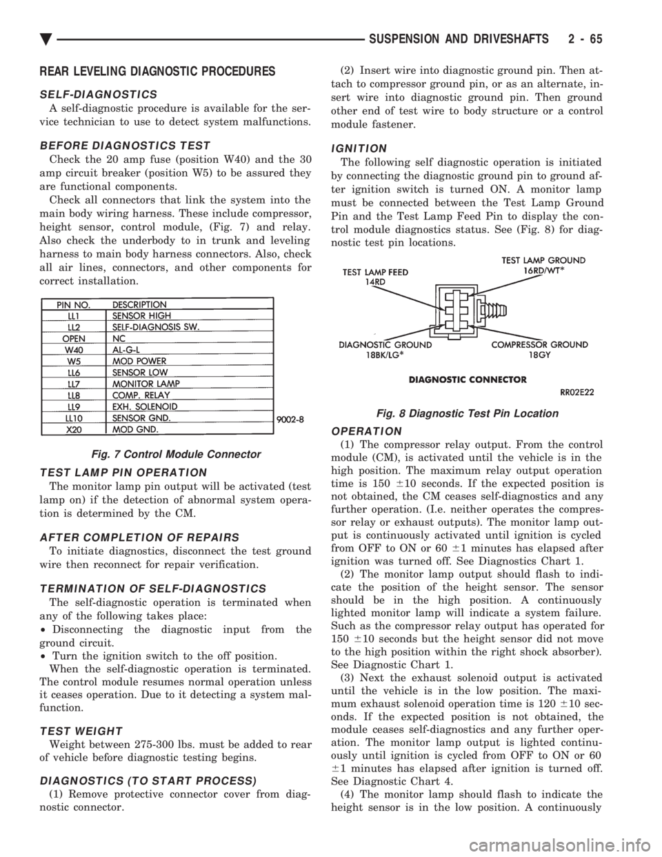
height sensor, control module, (Fig. 7) and relay.
Also check the underbody to in trunk and leveling
harness to main body harness connectors. Also, check
all air lines, connectors, and other components for
correct installation.
TEST LAMP PIN OPERATION
The monitor lamp pin output will be activated (test
lamp on) if the detection of abnormal system opera-
tion is determined by the CM.
AFTER COMPLETION OF REPAIRS
To initiate diagnostics, disconnect the test ground
wire then reconnect for repair verification.
TERMINATION OF SELF-DIAGNOSTICS
The self-diagnostic operation is terminated when
any of the following takes place:
² Disconnecting the diagnostic input from the
ground circuit.
² Turn the ignition switch to the off position.
When the self-diagnostic operation is terminated.
The control module resumes normal operation unless
it ceases operation. Due to it detecting a system mal-
function.
TEST WEIGHT
Weight between 275-300 lbs. must be added to rear
of vehicle before diagnostic testing begins.
DIAGNOSTICS (TO START PROCESS)
(1) Remove protective connector cover from diag-
nostic connector. (2) Insert wire into diagnostic ground pin. Then at-
tach to compressor ground pin, or as an alternate, in-
sert wire into diagnostic ground pin. Then ground
other end of test wire to body structure or a control
module fastener.
IGNITION
The following self diagnostic operation is initiated
by connecting the diagnostic ground pin to ground af-
ter ignition switch is turned ON. A monitor lamp
must be connected between the Test Lamp Ground
Pin and the Test Lamp Feed Pin to display the con-
trol module diagnostics status. See (Fig. 8) for diag-
nostic test pin locations.
OPERATION
(1) The compressor relay output. From the control
module (CM), is activated until the vehicle is in the
high position. The maximum relay output operation
time is 150 610 seconds. If the expected position is
not obtained, the CM ceases self-diagnostics and any
further operation. (I.e. neither operates the compres-
sor relay or exhaust outputs). The monitor lamp out-
put is continuously activated until ignition is cycled
from OFF to ON or 60 61 minutes has elapsed after
ignition was turned off. See Diagnostics Chart 1. (2) The monitor lamp output should flash to indi-
cate the position of the height sensor. The sensor
should be in the high position. A continuously
lighted monitor lamp will indicate a system failure.
Such as the compressor relay output has operated for
150 610 seconds but the height sensor did not move
to the high position within the right shock absorber).
See Diagnostic Chart 1. (3) Next the exhaust solenoid output is activated
until the vehicle is in the low position. The maxi-
mum exhaust solenoid operation time is 120 610 sec-
onds. If the expected position is not obtained, the
module ceases self-diagnostics and any further oper-
ation. The monitor lamp output is lighted continu-
ously until ignition is cycled from OFF to ON or 60
6 1 minutes has elapsed after ignition is turned off.
See Diagnostic Chart 4. (4) The monitor lamp should flash to indicate the
height sensor is in the low position. A continuouslyFig. 7 Control Module Connector
Fig. 8 Diagnostic Test Pin Location
Ä SUSPENSION AND DRIVESHAFTS 2 - 65
Page 225 of 2438
ABS EQUIPPED VEHICLE PERFORMANCE
Anti-Lock Brakes provide the driver with some
steering control during hard braking. However there
are conditions where the system does not provide any
benefit. In particular, hydroplaning is still possible
when the tires ride on a film of water. Hydroplaning
results in the vehicle tires leaving the road surface
rendering the vehicle almost uncontrollable. In addi-
tion, extreme steering maneuvers at high speed or
high speed cornering beyond limits of tire adhesion
to the road surface may cause vehicle skidding. So,
the ABS system is termed Anti-Lock instead of Anti-
Skid. One of the significant benefits of the ABS system is
that of maintaining steering control during hard
braking or during braking on slippery surfaces. It is
therefore possible to steer the vehicle while braking
on almost any road surface.
ABS SYSTEM SELF-DIAGNOSTICS
The ABS system has been designed with Self Diag-
nostic Capability. There are two self checks the sys-
tems performs every time the vehicle is started.
First, when the key is turned on the system performs
an electrical check called Start-Up Cycle. During this
check, the Red Brake Warning Lamp and the Amber
Anti-Lock Warning Lamp are illuminated. Then
turned off at the end of the test, after about 1 to 2
seconds. When the vehicle reaches a speed of about 3
to 4 miles per hour. The system performs a func-
tional check called Drive-Off. During Drive-Off. hy-
draulic valves are activated briefly to test their
function. Drive-Off can be detected as a series of
rapid clicks upon driving off the first time the car is
started. If the brake pedal is applied during Drive-
Off, the test is by-passed. Both of these conditions
are a normal part of the system self test. Most fault
conditions will set a ABS Fault Code in the (CAB),
which can be retrieved to aid in fault diagnosis. De-
tails can be found in Diagnosis Section.
ABS WARNING SYSTEMS OPERATION
The ABS system uses two methods for notifying
the driver of a system malfunction. These include the
standard Red Brake Warning Lamp and an Amber
Anti-Lock Warning Lamp, both located in the instru-
ment cluster. The purpose of these two lamps are dis-
cussed in detail below.
RED BRAKE WARNING LAMP
The Red Brake Warning Lamp, located in the in-
strument cluster, will Turn On to warn the driver of
brake system conditions that may result in reduced
braking ability. The lamp is also turned on when the
parking brake is not fully released. Conditions which
may cause the Red Brake Warning Lamp to Turn On
include: ²
Parking brake not fully released. If the parking
brake is applied or not fully released. The switch on the
parking brake pedal assembly will ground the Red
Brake Warning Lamp circuit and cause the lamp to
turn on. On vehicles equipped with mechanical instru-
ment clusters, the Amber Anti-Lock Lamp will turn on
if the vehicle is driven above 3 miles per hour with the
Parking Brake applied.
² Low brake fluid. The fluid level sensor in the hy-
draulic assembly reservoir will ground the Red Brake
Warning Lamp circuit if low brake fluid level is de-
tected. In addition, ABS will be deactivated above 3
miles per hour and the Amber Anti-Lock Warning
Lamp will be illuminated. If the vehicle is equipped
with EVIC, a low fluid condition will also cause the
Low Brake Fluid message to appear.
² Low Accumulator Pressure. In the event of low
accumulator pressure, the dual function pressure
switch in the hydraulic assembly will signal the (CAB)
to ground the Red Brake Warning Lamp circuit. This
will cause the Red Brake Warning Lamp to turn on.
Low accumulator pressure also results in the activa-
tion of the Yellow Anti-Lock Warning Lamp. Low accu-
mulator pressure may result in loss of power assist.
² Modulator Or (CAB) Faults. The modulator assem-
bly or (CAB) may turn on the Yellow Anti-Lock Warn-
ing Lamp, if certain faults are detected in either the
modulator assembly or the (CAB).
² Bulb check. As a bulb check, the Red Brake Warning
Lamp will illuminate whenever the ignition switch is
placed in the crank position. Illumination of the red Brake Warning Lamp
may indicate reduced braking ability. A vehicle
that has the Red Brake Warning Lamp ON should
not be driven except to do diagnostic procedures
described in Section 2 of this manual. Most con-
ditions that turn on the Red Brake Warning
Lamp will also turn on the Amber Anti-Lock
Warning Lamp, consequently disabling the Anti-
Lock function.
ANTI-LOCK WARNING LAMP
The Anti-Lock Warning Lamp is located in the in-
strument cluster and is Amber in color. The Amber
Anti-Lock Warning Lamp is illuminated when the
(CAB) detects a condition that results in a shutdown of
Anti-Lock function. The Amber Anti-Lock Warning
Lamp is normally on until the (CAB) completes its self
tests and turns the lamp off. For example, if the (CAB)
is disconnected, the lamp is on. Display of the Amber Anti-Lock Warning Lamp
without the Red Brake Warning Lamp indicates
only that Anti-Lock function has been disabled.
Power assisted normal braking is unaffected.
Ä ANTI-LOCK 10 BRAKE SYSTEM 5 - 75
Page 232 of 2438
The primary functions of the (CAB) are:
² (1) Detect wheel locking tendencies.
² (2) Control fluid modulation to the brakes while in
Anti-Lock mode.
² (3) Monitor the system for proper operation.
² (4) Provide communication to the DRB II while in
diagnostic mode. The (CAB) continuously monitors the speed of each
wheel, through the signals generated at the Wheel
Speed Sensors, to determine if any wheel is begin-
ning to lock. When a wheel locking tendency is de-
tected, the (CAB) will isolate the master cylinder
from the wheel brakes. This is done by activating the
Isolation Valves. The (CAB) then commands the ap-
propriate Build or Decay valves to modulate brake
fluid pressure in some or all of the hydraulic circuits.
The fluid used for modulation comes from the booster
servo circuit. The (CAB) continues to control pres-
sure in individual hydraulic circuits until a locking
tendency is no longer present. The (ABS) system is constantly monitored by the
(CAB) for proper operation. If the (CAB) detects a
fault, it can disable the Anti-Lock braking function.
Depending on the fault, the (CAB) will light one or
both of the brake warning lamps. The (CAB) contains a System Diagnostic Program
which triggers the brake system warning lamps
when a system fault is detected. Faults are stored in
a diagnostic program memory. There are 19 fault
codes that may be stored in the (CAB) and displayed
through the DRB II. These fault codes will remain in
the (CAB) memory even after the ignition has been
turned off. These fault codes will remain in memory
until they are cleared with the DRB II, or automati-
cally erased from the memory after (50) ignition
switch on/off cycles.
CONTROLLER ANTI-LOCK BRAKE (INPUTS)
² Four wheel speed sensors.
² Boost pressure transducer.
² Primary pressure transducer.
² Low fluid level switch.
² Differential pressure switch.
² Parking brake switch.
² Dual function pressure switch (warning pressure
only)
² Stop lamp switch.
² Ignition switch.
² System relay voltage.
² Ground.
² Low Accumulator
CONTROLLER ANTI-LOCK BRAKE (OUTPUTS)
²Ten modulator valves-3 decay, 3 build and 4 isola-
tion.
² Red Brake warning lamp.
² Amber Anti-Lock Warning Lamp.
² System relay actuation. ²
Diagnostic communication.
ABS SYSTEM DIAGNOSTIC CONNECTOR
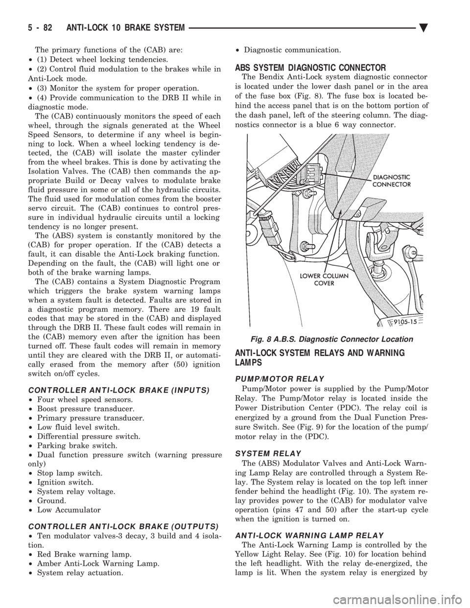
The Bendix Anti-Lock system diagnostic connector
is located under the lower dash panel or in the area
of the fuse box (Fig. 8). The fuse box is located be-
hind the access panel that is on the bottom portion of
the dash panel, left of the steering column. The diag-
nostics connector is a blue 6 way connector.
ANTI-LOCK SYSTEM RELAYS AND WARNING
LAMPS
PUMP/MOTOR RELAY
Pump/Motor power is supplied by the Pump/Motor
Relay. The Pump/Motor relay is located inside the
Power Distribution Center (PDC). The relay coil is
energized by a ground from the Dual Function Pres-
sure Switch. See (Fig. 9) for the location of the pump/
motor relay in the (PDC).
SYSTEM RELAY
The (ABS) Modulator Valves and Anti-Lock Warn-
ing Lamp Relay are controlled through a System Re-
lay. The System relay is located on the top left inner
fender behind the headlight (Fig. 10). The system re-
lay provides power to the (CAB) for modulator valve
operation (pins 47 and 50) after the start-up cycle
when the ignition is turned on.
ANTI-LOCK WARNING LAMP RELAY
The Anti-Lock Warning Lamp is controlled by the
Yellow Light Relay. See (Fig. 10) for location behind
the left headlight. With the relay de-energized, the
lamp is lit. When the system relay is energized by
Fig. 8 A.B.S. Diagnostic Connector Location
5 - 82 ANTI-LOCK 10 BRAKE SYSTEM Ä
Page 239 of 2438
Brake Warning Lamp may indicate reduced
braking ability. The following procedure should
be used to test drive an ABS complaint:(1) Ignition on. Turn the ignition to the ON position
without starting the car and wait until the Red Brake
Warning Lamp and Amber Anti-Lock Warning Lamp
turn off. This will allow the pump to charge the
accumulator to operating pressure. If the warning
lamp(s) do not turn off, go to step 3. (2) Ignition off for 15 seconds.
(3) Start car. Wait for displays to return to normal
operating mode before proceeding. (4) With Shift lever in PARK, slowly depress brake
pedal and release. (5) Drive vehicle a short distance. During this test
drive, be sure that the vehicle achieves at least 20 mph.
Then brake to at least one complete stop and accelerate
slowly back up to at least 20 mph. (6) If a functional problem with the A.B.S. system is
determined while test driving a vehicle. Refer to the
Bendix Anti-Lock 10 Diagnostics Manual for required
test procedures and proper use of the DRB II tester.
CAUTION: The following are general precautions that
should be observed when servicing and diagnosing
the ABS system and/or other vehicle systems. Failure
to observe these precautions may result in ABS
system damage.
(1) If welding work is to be performed on the vehicle
using an arc welder, the (CAB) should be disconnected
before the welding operation begins. (2) The (CAB) and hydraulic assembly 10 way con-
nectors should never be connected or disconnected with
the ignition on. (3) Some components of the ABS system are not
serviced separately and must be serviced as complete
assemblies. Do not disassemble any component which
is designated as non-serviceable. (4) Always de-pressurize the Hydraulic Accu-
mulator when performing any work that re-
quires disconnecting any hydraulic tube, flex
hose or fitting. The ABS system uses brake fluid
at high pressure. Failure to de-pressurize the
accumulator may result in personal injury
and/or damage to painted surfaces. Brake fluid will damage painted surfaces. If brake
fluid is spilled on any painted surfaces, wash off with
water immediately.
DE-PRESSURIZING HYDRAULIC ACCUMULA- TOR
The ABS pump/motor assembly keeps the hydraulic
accumulator charged between approximately 11,032
and 13,790 kPa (1600 and 2000 psi) anytime key is in the ON position. The pump/motor assembly
cannot run if the ignition is off or either battery ca-
ble is disconnected. Unless otherwise specified, the hydraulic accumu-
lator should be de-pressurized before disassembling
any portion of the hydraulic system. The following
procedure should be used to de-pressurize the hy-
draulic accumulator: (1) With ignition off, or either battery cable discon-
nected, pump the brake pedal a minimum of 40 times
using approximately 50 pounds of pedal force. A no-
ticeable change in pedal feel will occur when the ac-
cumulator becomes discharged. (2) When a definite increase in pedal effort is felt,
pump the pedal a few additional times. This will in-
sure removal of all hydraulic pressure from the
brake system.
WHEEL SPEED SENSOR CABLES
Proper installation of wheel speed sensor cables is
critical to continued ABS system operation. Be sure
that cables are installed and routed properly. Failure
to install cables in their retainers, as shown in Sec-
tion 3 of this manual. May result in contact with
moving parts or over extension of cables, resulting in
an open circuit.
MECHANICAL DIAGNOSTICS AND SERVICE
PROCEDURES
SPECIAL SERVICE TOOLS
Some diagnostic procedures in this section require
the use of special service tools. Each of these tools is
described below.
DRB II DIAGNOSTIC TESTER
Some of the diagnostic procedures that are ex-
plained in this section require the use of the DRB II
DIAGNOSTICS TESTER to insure that proper diag-
nostics are performed. Refer to those sections for
proper testing procedures and the DRB II manual for
its proper operational information.
MST-6163 PRESSURE TESTER
Some diagnostic procedures in this manual require
the use of the MST-6163 pressure gauge and adaptor
(Fig. 2). Pressure Gauge, Special Tool MST-6163 is
required to measure accumulator pressure during
certain phases of ABS operation. The pressure gauge
and adaptor should be installed as follows: (1) De-pressurize the accumulator by pumping the
brake pedal a minimum of 40 times with the ignition
off. The procedure is fully explained under De-Pres-
surizing Hydraulic Accumulator which is described
earlier in this System Diagnosis Section.
Ä ANTI-LOCK 10 BRAKE SYSTEM 5 - 89
Page 242 of 2438
(11) Remove all special tools previously installed,
from the ABS hydraulic assembly. (12) Install accumulator port plug into hydraulic
assembly. Torque accumulator port plug to 12 N Im(9
ft. lbs.). (13) Install high pressure brake hose from the
pump motor assembly into hydraulic fitting on ABS
hydraulic assembly. Torque high pressure brake hose
tube nut to 16 N Im (145 in. lbs.).
(14) Turn ignition switch to the run position to en-
ergize the pump/motor assembly and pressurize hy-
draulic system. Check for leakage at the hydraulic
assembly to hydraulic bladder accumulator fitting. (15) Again de-pressurize accumulator by pumping
brake pedal a minimum of 40 times. Use procedure
described in De-Pressurizing Hydraulic Accumulator
in this section of the service manual. (16) Then check the brake fluid level in the hy-
draulic assembly reservoir. If brake fluid level is low,
fill reservoir to proper level with Mopar tbrake fluid
or equivalent conforming to DOT 3 requirements.
INTERMITTENT FAULTS
As with almost any electronic system, intermittent
faults in the ABS system may be difficult to accu-
rately diagnose. Most intermittent faults are caused by faulty elec-
trical connections or wiring. When an intermittent
fault is encountered, check suspect circuits for: (1) Poor mating of electrical connector halves, or
electrical terminals not fully seated in the connector
body. (2) Improperly formed or damaged electrical termi-
nals. All connector terminals in a suspect circuit
should be carefully reformed to increase contact ten-
sion. (3) Poor terminal to wire connection. This requires
removing the terminal from the connector body and
inspecting for proper terminal to wire connection. If a visual check does not find the cause of the
problem, operate the vehicle in an attempt to dupli-
cate the condition and record the Fault Code. Most failures of the ABS system will disable the
Anti-Lock function for the entire ignition cycle even
if the fault clears before ignition key-off. There are
some failure conditions however, which will allow
ABS operation to resume during the ignition cycle in
which a failure occurred. If the failure conditions are
no longer present. The following conditions may result in intermittent
illumination of the Red Brake Warning Lamp and/or
Amber Anti-Lock Warning Lamp. All other failures
will cause the lamp(s) to remain on until the ignition
switch is turned off. Circuits and or components in-
volving these inputs to the (CAB) should be investi-
gated if a complaint of intermittent warning system
operation is encountered. ²
Low system voltage. If low system voltage is de-
tected by the (CAB), the (CAB) will turn on the Am-
ber Anti-Lock Warning Lamp until normal system
voltage is achieved. Once normal voltage is seen at
the (CAB), normal operation resumes.
² Low Brake Fluid. A low brake fluid condition will
cause the Red Brake Warning Lamp to illuminate.
When the fluid sensor again indicates an acceptable
fluid level, the Red Brake Warning Lamp will go out.
This condition may exist during hard cornering or
while the vehicle is on a grade. If the vehicle is in
motion above 3 M.P.H. the Amber Anti-Lock Warn-
ing Lamp will also be turned on.
² Low Accumulator Pressure. Low Accumulator
Pressure will cause both the Red Brake Warning and
Amber Anti-Lock Warning Lamps to illuminate.
Once normal operating pressure is achieved, the
lamps will extinguish and the system will return to
normal operation. Additionally, any condition that results in an inter-
ruption of power to the (CAB) or hydraulic assembly.
May cause the Red Brake Warning and Amber Anti-
Lock Warning Lamps to illuminate intermittently. All the conditions (or faults) mentioned above, can
store a fault code in the (CAB) module.
ABS BRAKE SYSTEM DIAGNOSTIC FEATURES
SYSTEM SELF DIAGNOSIS
The ABS system is equipped with a diagnostic ca-
pability that may be used to assist in isolation of
ABS faults. The features of the diagnostics system
are described below.
CONTROLLER ANTI-LOCK BRAKE (CAB)
Fault codes are kept in a Non-Volatile memory un-
til either erased by the technician using the DRB II
or erased automatically after 50 ignition cycles (key
ON-OFF cycles). The only fault that will not be
erased after 50 (KEY CYCLES) is the (CAB) fault.
The (CAB) fault can only be erased by using the
DRB II diagnostic tester. More than one fault can be
stored at a time. The number of key cycles since the
most recent fault was stored is also displayed. Most
functions of the (CAB) and (ABS) system can be ac-
cessed by the technician for testing and diagnostic
purposes by using the DRB II Diagnostic Tester.
START-UP CYCLE
The START-UP CYCLE takes place immediately
after the ignition switch is turned on. It is an elec-
trical check of basic electrical functions such as the
System Relay and Anti-Lock Warning Lamp Relay.
During this check, the Amber Anti-Lock Warning
Lamp is turned on, then turned off at the end of the
test. The test takes approximatel y1-2seconds to
complete.
5 - 92 ANTI-LOCK 10 BRAKE SYSTEM Ä
Page 269 of 2438
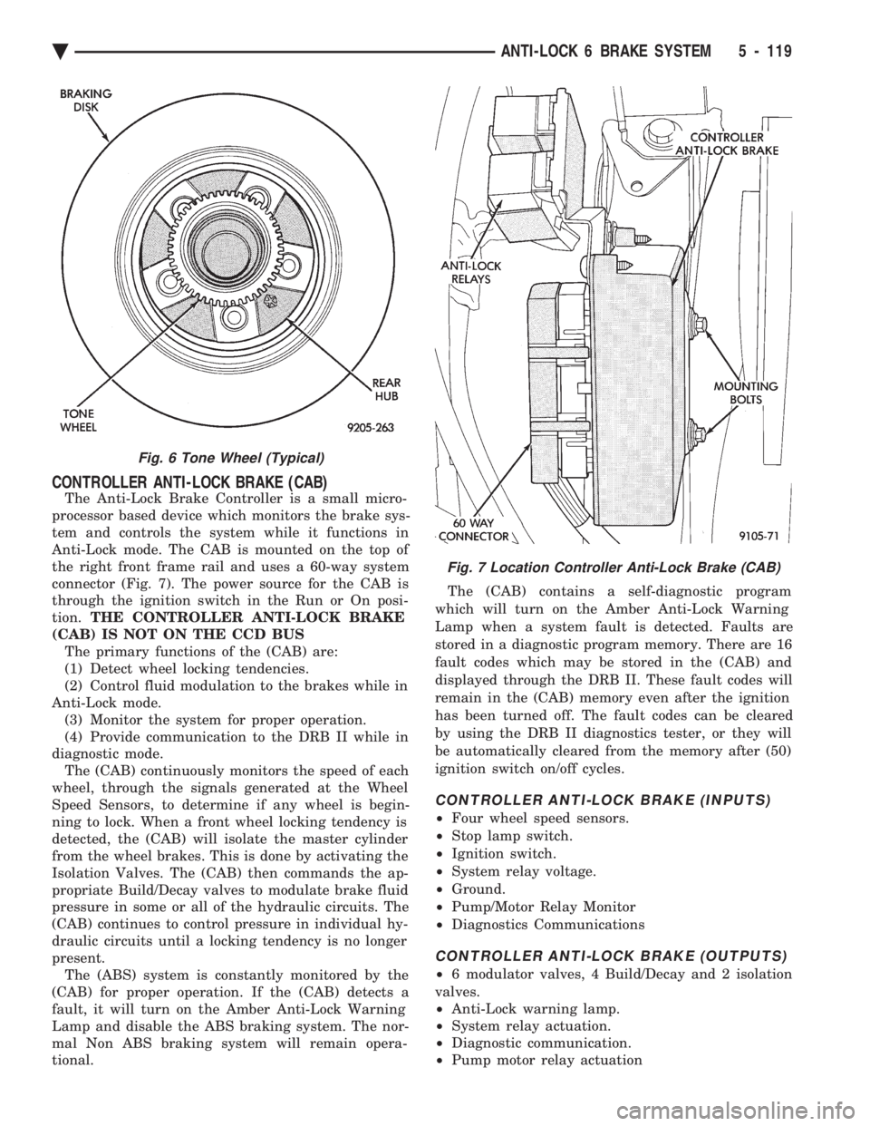
CONTROLLER ANTI-LOCK BRAKE (CAB)
The Anti-Lock Brake Controller is a small micro-
processor based device which monitors the brake sys-
tem and controls the system while it functions in
Anti-Lock mode. The CAB is mounted on the top of
the right front frame rail and uses a 60-way system
connector (Fig. 7). The power source for the CAB is
through the ignition switch in the Run or On posi-
tion. THE CONTROLLER ANTI-LOCK BRAKE
(CAB) IS NOT ON THE CCD BUS The primary functions of the (CAB) are:
(1) Detect wheel locking tendencies.
(2) Control fluid modulation to the brakes while in
Anti-Lock mode. (3) Monitor the system for proper operation.
(4) Provide communication to the DRB II while in
diagnostic mode. The (CAB) continuously monitors the speed of each
wheel, through the signals generated at the Wheel
Speed Sensors, to determine if any wheel is begin-
ning to lock. When a front wheel locking tendency is
detected, the (CAB) will isolate the master cylinder
from the wheel brakes. This is done by activating the
Isolation Valves. The (CAB) then commands the ap-
propriate Build/Decay valves to modulate brake fluid
pressure in some or all of the hydraulic circuits. The
(CAB) continues to control pressure in individual hy-
draulic circuits until a locking tendency is no longer
present. The (ABS) system is constantly monitored by the
(CAB) for proper operation. If the (CAB) detects a
fault, it will turn on the Amber Anti-Lock Warning
Lamp and disable the ABS braking system. The nor-
mal Non ABS braking system will remain opera-
tional. The (CAB) contains a self-diagnostic program
which will turn on the Amber Anti-Lock Warning
Lamp when a system fault is detected. Faults are
stored in a diagnostic program memory. There are 16
fault codes which may be stored in the (CAB) and
displayed through the DRB II. These fault codes will
remain in the (CAB) memory even after the ignition
has been turned off. The fault codes can be cleared
by using the DRB II diagnostics tester, or they will
be automatically cleared from the memory after (50)
ignition switch on/off cycles.
CONTROLLER ANTI-LOCK BRAKE (INPUTS)
² Four wheel speed sensors.
² Stop lamp switch.
² Ignition switch.
² System relay voltage.
² Ground.
² Pump/Motor Relay Monitor
² Diagnostics Communications
CONTROLLER ANTI-LOCK BRAKE (OUTPUTS)
²6 modulator valves, 4 Build/Decay and 2 isolation
valves.
² Anti-Lock warning lamp.
² System relay actuation.
² Diagnostic communication.
² Pump motor relay actuation
Fig. 6 Tone Wheel (Typical)
Fig. 7 Location Controller Anti-Lock Brake (CAB)
Ä ANTI-LOCK 6 BRAKE SYSTEM 5 - 119
Page 305 of 2438
(4) Provide communication to the DRB II while in
the Antilock brakes diagnostic mode. The CAB continuously monitors the speed of each
wheel, through the signals generated at the Wheel
Speed Sensors. This is used to determine if any
wheel of the vehicle is beginning to lock-up (skid)
when the brakes are applied. When a wheel locking
tendency is detected during brake apply. The CAB
commands the appropriate Build/Decay valves to
modulate brake fluid pressure in some or all of the
hydraulic circuits. The CAB continues to control
pressure in individual hydraulic circuits until a lock-
ing tendency is no longer present. The ABS system is constantly monitored by the
CAB for proper operation. If the CAB detects a fault,
it will turn on the Amber Antilock Warning Lamp
and disable the ABS brake system. The normal Non
ABS brake system will remain operational. The CAB contains a self-diagnostic program which
will turn on the Amber Antilock Warning Lamp
when a system fault is detected. Faults are stored in
a diagnostic program memory. There are 16 fault
codes which may be stored in the CAB and displayed
through the DRB II. These fault codes will remain in
the CAB memory even after the ignition has been
turned off. The fault codes can be cleared by using
the DRB II diagnostics tester, or they will be auto-
matically cleared from the memory after (50) ignition
switch on/off cycles.
CONTROLLER ANTILOCK BRAKE (INPUTS)
² Four wheel speed sensors.
² Stop lamp switch.
² Ignition switch.
² System relay voltage.
² Ground.
² Pump/Motor Relay Monitor
² Diagnostics Communications
CONTROLLER ANTILOCK BRAKE (OUTPUTS)
²4 Build/Decay valves.
² Antilock warning lamp.
² System relay actuation.
² Diagnostic communication.
² Pump/Motor relay actuation
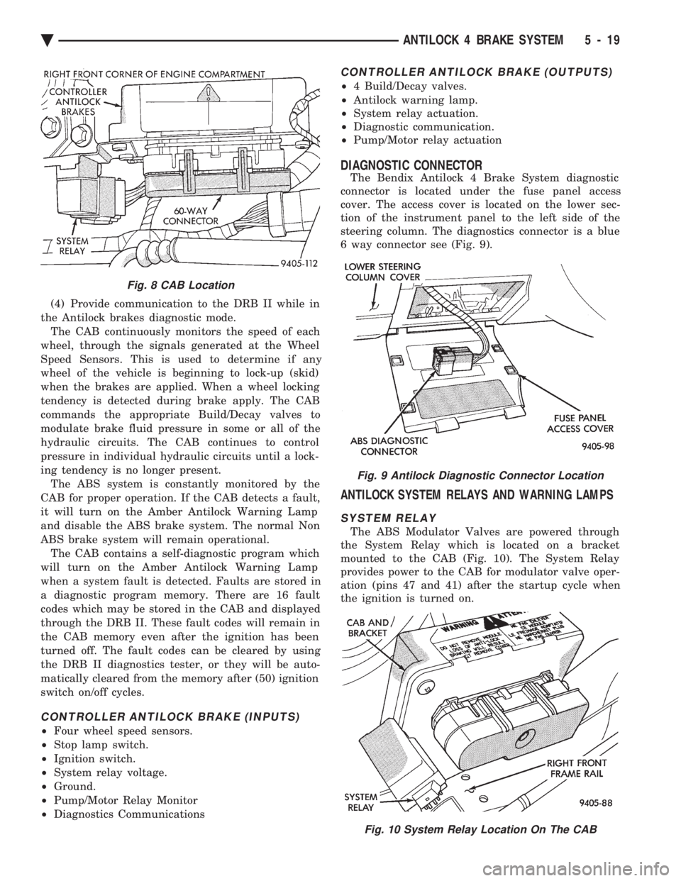
DIAGNOSTIC CONNECTOR
The Bendix Antilock 4 Brake System diagnostic
connector is located under the fuse panel access
cover. The access cover is located on the lower sec-
tion of the instrument panel to the left side of the
steering column. The diagnostics connector is a blue
6 way connector see (Fig. 9).
ANTILOCK SYSTEM RELAYS AND WARNING LAMPS
SYSTEM RELAY
The ABS Modulator Valves are powered through
the System Relay which is located on a bracket
mounted to the CAB (Fig. 10). The System Relay
provides power to the CAB for modulator valve oper-
ation (pins 47 and 41) after the startup cycle when
the ignition is turned on.
Fig. 8 CAB Location
Fig. 9 Antilock Diagnostic Connector Location
Fig. 10 System Relay Location On The CAB
Ä ANTILOCK 4 BRAKE SYSTEM 5 - 19
Page 310 of 2438
manual. May result in contact with moving parts or
over extension of cables, resulting in component fail-
ure and an open circuit.
MECHANICAL DIAGNOSTICS AND SERVICE
PROCEDURES
SPECIAL SERVICE TOOL
Some diagnostic procedures in this section require
the use of the DRB diagnostics tester. The proper ap-
plication and procedures for the use of this tool are
described below.
DRB DIAGNOSTIC TESTER
Some of the diagnostic procedures that are ex-
plained in this section require the use of the DRB Di-
agnostics Tester to insure that proper diagnostics are
performed. Refer to those sections for proper testing
procedures and the DRB operators manual for its
proper operational information.
INTERMITTENT FAULTS
As with virtually any electronic system, intermit-
tent faults in the ABS system may be difficult to ac-
curately diagnose. Most intermittent faults are caused by faulty elec-
trical connections or wiring. When an intermittent
fault is encountered, check suspect circuits for: (1) Poor mating of wiring harness connector halves
or terminals not fully seated in the connector body. (2) Improperly formed or damaged terminals. All
connector terminals in a suspect circuit should be
checked and carefully reformed to increase contact
tension with its mating terminal. (3) Poor terminal to wire connection. This requires
removing the terminal from the connector body to in-
spect. (4) Pin presence in the connector assembly
(5) Connector push-in, spread, and corrosion.
If a visual check does not find the cause of the
problem, operate the car in an attempt to duplicate
the condition and record the set Fault code. Most failures of the ABS system will disable the
Antilock function for the entire ignition cycle even if
the fault clears before key-off. There are some failure
conditions, however, which will allow ABS operation
to resume during the ignition cycle in which it oc-
curred, if the failure condition is no longer present.
The following conditions may result in intermittent
illumination of the Amber Antilock Warning Lamp.
All other failures will cause the lamp to remain on
until the ignition switch is turned off. Circuits in-
volving these inputs to the CAB should be investi-
gated if a complaint of intermittent warning system
operation is encountered. (1) Low system voltage: If Low System Voltage is
detected by the CAB, the CAB will turn on the Am-
ber Antilock Warning Lamp until normal system voltage is achieved. Once normal voltage is seen at
the CAB, normal operation resumes.
(2) Antilock system and pump/motor relay. If the
relays fail to make the ground circuit connection or
has an intermittent ground. The CAB will turn on
the Amber Antilock Warning Light. (3) Excess decay, an extended pressure decay pe-
riod, will turn on the Amber Antilock Warning Light
until the vehicle comes to a complete stop. Additionally, any condition which results in inter-
ruption of electrical current to the CAB or modulator
assembly, may cause the Amber Antilock Warning
Lamp to turn on intermittently.
ABS BRAKE SYSTEM DIAGNOSTIC FEATURES
ABS SYSTEM SELF DIAGNOSIS
The ABS system is equipped with a self diagnostic
capability which may be used to assist in isolation of
ABS faults. The features of the self diagnostics sys-
tem are described below.
START-UP CYCLE
The self diagnostic ABS start up cycle begins when
the ignition switch is turned to the on position. An
electrical check is completed on the ABS components.
Such as Wheel Speed Sensor Continuity and System
and other Relay continuity. During this check the
Amber Antilock Light is turned on for approximately
1- 2 seconds. Further Functional testing is accomplished once
the vehicle is set in motion, known as drive-off.
² The solenoid valves and the pump/motor are acti-
vated briefly to verify function.
² The voltage output from the wheel speed sensors is
verified to be within the correct operating range. If the vehicle is not set in motion within 3 minutes
from the time the ignition switch is set in the on po-
sition. The solenoid test is bypassed but the pump/
motor is activated briefly to verify that it is
operating correctly.
CONTROLLER ANTILOCK BRAKE CAB
Fault codes are kept in a Non-Volatile memory un-
til either erased by the technician using the DRB or
erased automatically after 50 ignition cycles (key
ON-OFF cycles). The only fault that will not be
erased after 50 (KEY CYCLES) is the CAB fault. A
CAB fault can only be erased by the technician using
the DRB diagnostic tester. More than one fault can
be stored at a time. The number of key cycles since
the most recent fault was stored is also displayed.
Most functions of the CAB and ABS system can be
accessed by the technician for testing and diagnostic
purposes by using the DRB.
5 - 24 ANTILOCK 4 BRAKE SYSTEM Ä
Page 396 of 2438
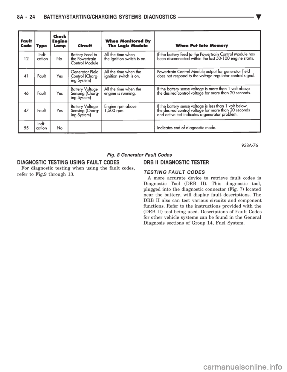
DIAGNOSTIC TESTING USING FAULT CODES
For diagnostic testing when using the fault codes,
refer to Fig.9 through 13.
DRB II DIAGNOSTIC TESTER
TESTING FAULT CODES
A more accurate device to retrieve fault codes is
Diagnostic Tool (DRB II). This diagnostic tool,
plugged into the diagnostic connector (Fig. 7) located
near the battery, will display fault descriptions. The
DRB II also can test various circuits and component
functions. Refer to the instructions provided with the
(DRB II) tool being used. Descriptions of Fault Codes
for other vehicle systems can be found in the General
Diagnosis sections of Group 14, Fuel System.
Fig. 8 Generator Fault Codes
8A - 24 BATTERY/STARTING/CHARGING SYSTEMS DIAGNOSTICS Ä
Page 403 of 2438
BATTERY/STARTER/GENERATOR SERVICE
CONTENTS
page page
BATTERY REMOVAL, INSTALLATION AND SERVICE ............................. 1
GENERATOR ............................ 9 SPECIFICATIONS
....................... 12
STARTER ............................... 4
BATTERY REMOVAL, INSTALLATION AND SERVICE
GENERAL INFORMATION
This first section will cover Battery replacement and
service procedures only. For Battery diagnostic proce-
dures, refer to Group 8A, Battery/Starting/Charging
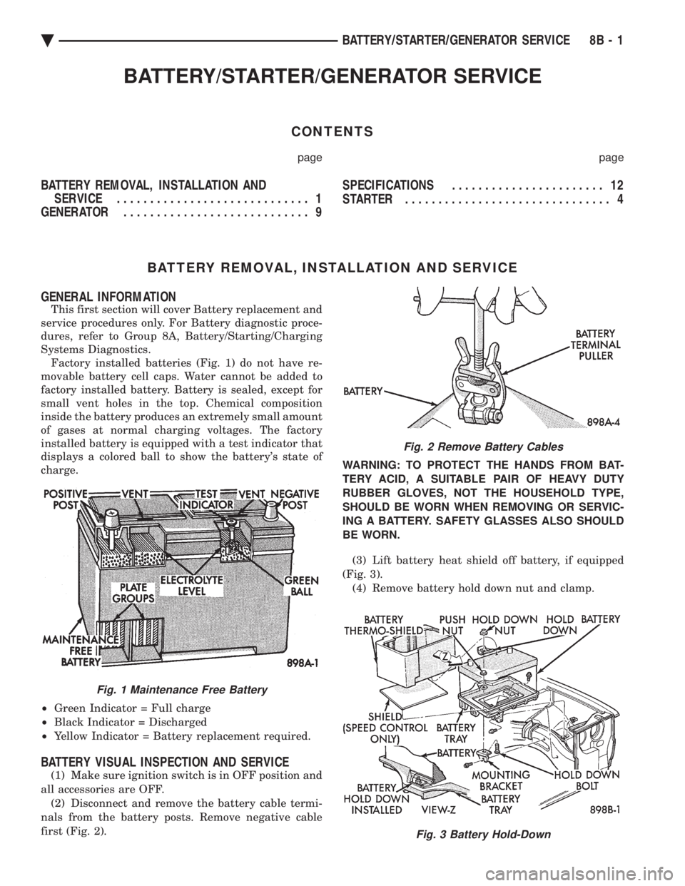
Systems Diagnostics. Factory installed batteries (Fig. 1) do not have re-
movable battery cell caps. Water cannot be added to
factory installed battery. Battery is sealed, except for
small vent holes in the top. Chemical composition
inside the battery produces an extremely small amount
of gases at normal charging voltages. The factory
installed battery is equipped with a test indicator that
displays a colored ball to show the battery's state of
charge.
² Green Indicator = Full charge
² Black Indicator = Discharged
² Yellow Indicator = Battery replacement required.
BATTERY VISUAL INSPECTION AND SERVICE
(1) Make sure ignition switch is in OFF position and
all accessories are OFF. (2) Disconnect and remove the battery cable termi-
nals from the battery posts. Remove negative cable
first (Fig. 2). WARNING: TO PROTECT THE HANDS FROM BAT-
TERY ACID, A SUITABLE PAIR OF HEAVY DUTY
RUBBER GLOVES, NOT THE HOUSEHOLD TYPE,
SHOULD BE WORN WHEN REMOVING OR SERVIC-
ING A BATTERY. SAFETY GLASSES ALSO SHOULD
BE WORN.
(3) Lift battery heat shield off battery, if equipped
(Fig. 3). (4) Remove battery hold down nut and clamp.
Fig. 1 Maintenance Free Battery
Fig. 2 Remove Battery Cables
Fig. 3 Battery Hold-Down
Ä BATTERY/STARTER/GENERATOR SERVICE 8B - 1