gas mileage CHEVROLET DYNASTY 1993 Service Manual
[x] Cancel search | Manufacturer: CHEVROLET, Model Year: 1993, Model line: DYNASTY, Model: CHEVROLET DYNASTY 1993Pages: 2438, PDF Size: 74.98 MB
Page 45 of 2438
² SG service engine oil is a high quality crankcase
lubricant designed for use in all naturally aspirated
engines. If SG service engine oil is used in turbo-
charged engine, change engine oil at every 4 800
km (3,000 miles) or three months.
² SG/CD service engine oil is a high quality crank-
case lubricant designed for use in most naturally as-
pirated and turbocharged gasoline or diesel engines.
FLEXIBLE FUEL VEHICLES
Vehicles operated using Flexible Fuel (M85) re-
quire engine oil that meet or exceed Chrysler Stan-
dard MS-9214. Mopar Flexible Fuel engine oil or
equivalent should be used when adding or changing
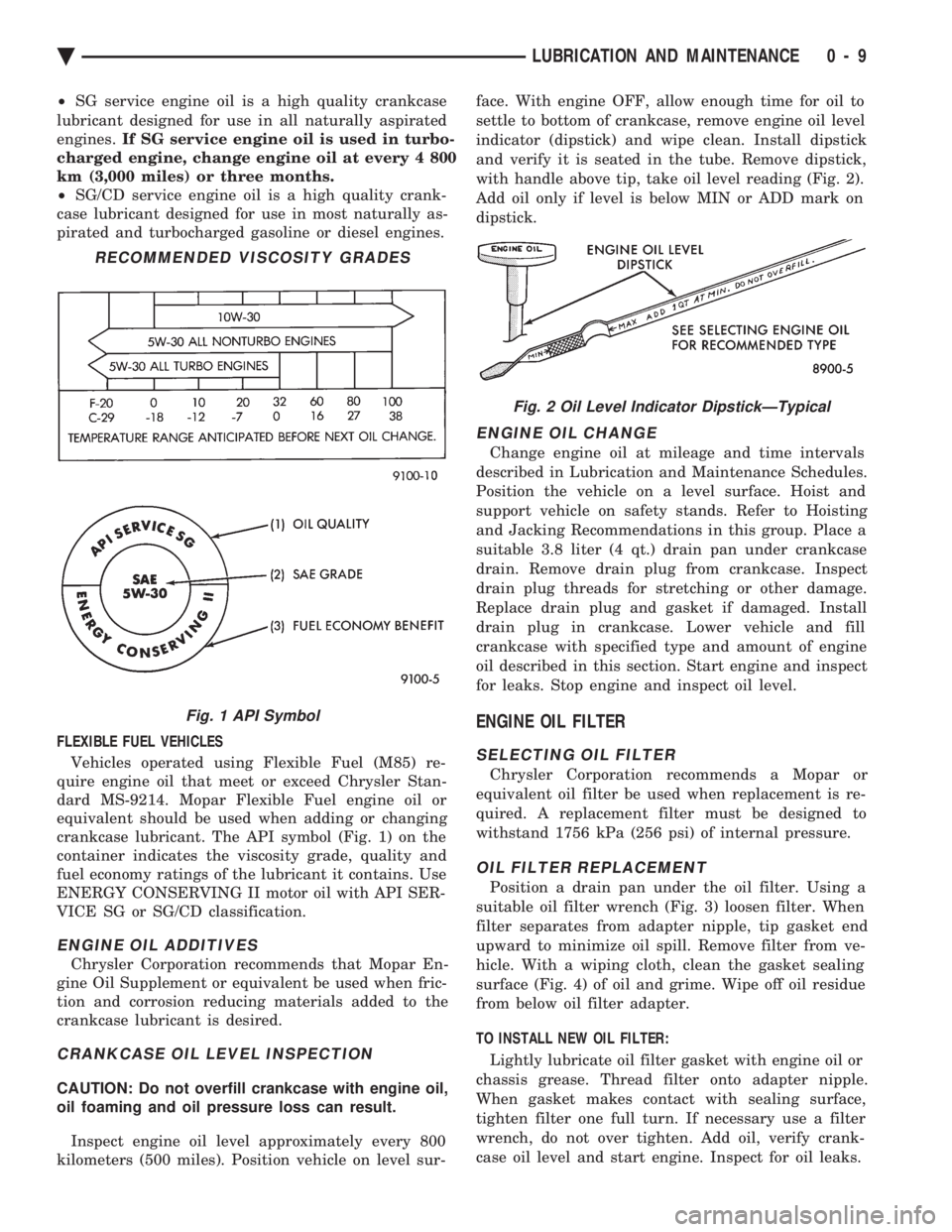
crankcase lubricant. The API symbol (Fig. 1) on the
container indicates the viscosity grade, quality and
fuel economy ratings of the lubricant it contains. Use
ENERGY CONSERVING II motor oil with API SER-
VICE SG or SG/CD classification.
ENGINE OIL ADDITIVES
Chrysler Corporation recommends that Mopar En-
gine Oil Supplement or equivalent be used when fric-
tion and corrosion reducing materials added to the
crankcase lubricant is desired.
CRANKCASE OIL LEVEL INSPECTION
CAUTION: Do not overfill crankcase with engine oil,
oil foaming and oil pressure loss can result.
Inspect engine oil level approximately every 800
kilometers (500 miles). Position vehicle on level sur- face. With engine OFF, allow enough time for oil to
settle to bottom of crankcase, remove engine oil level
indicator (dipstick) and wipe clean. Install dipstick
and verify it is seated in the tube. Remove dipstick,
with handle above tip, take oil level reading (Fig. 2).
Add oil only if level is below MIN or ADD mark on
dipstick.
ENGINE OIL CHANGE
Change engine oil at mileage and time intervals
described in Lubrication and Maintenance Schedules.
Position the vehicle on a level surface. Hoist and
support vehicle on safety stands. Refer to Hoisting
and Jacking Recommendations in this group. Place a
suitable 3.8 liter (4 qt.) drain pan under crankcase
drain. Remove drain plug from crankcase. Inspect
drain plug threads for stretching or other damage.
Replace drain plug and gasket if damaged. Install
drain plug in crankcase. Lower vehicle and fill
crankcase with specified type and amount of engine
oil described in this section. Start engine and inspect
for leaks. Stop engine and inspect oil level.
ENGINE OIL FILTER
SELECTING OIL FILTER
Chrysler Corporation recommends a Mopar or
equivalent oil filter be used when replacement is re-
quired. A replacement filter must be designed to
withstand 1756 kPa (256 psi) of internal pressure.
OIL FILTER REPLACEMENT
Position a drain pan under the oil filter. Using a
suitable oil filter wrench (Fig. 3) loosen filter. When
filter separates from adapter nipple, tip gasket end
upward to minimize oil spill. Remove filter from ve-
hicle. With a wiping cloth, clean the gasket sealing
surface (Fig. 4) of oil and grime. Wipe off oil residue
from below oil filter adapter.
TO INSTALL NEW OIL FILTER: Lightly lubricate oil filter gasket with engine oil or
chassis grease. Thread filter onto adapter nipple.
When gasket makes contact with sealing surface,
tighten filter one full turn. If necessary use a filter
wrench, do not over tighten. Add oil, verify crank-
case oil level and start engine. Inspect for oil leaks.
RECOMMENDED VISCOSITY GRADES
Fig. 1 API Symbol
Fig. 2 Oil Level Indicator DipstickÐTypical
Ä LUBRICATION AND MAINTENANCE 0 - 9
Page 50 of 2438
PCV SYSTEM TEST
Refer to group 25, Emission Control System for
proper procedures to test PCV system.
FUEL RECOMMENDATIONS
Chrysler Corporation recommends that only fuel pur-
chased from a reputable retailer be used. Use high qual-
ity, unleaded gasoline to provide satisfactory
driveability and highest fuel economy. Gasoline contain-
ing detergent and corrosion control additives are desire-
able. If the engine develops spark knock (audible ping),
poor performance, hard starting or stalling, purchase
fuel from another source. Engine performance can vary
when using different brands of gasoline with the same
octane rating. Occasional light engine spark knock un-
der heavy acceleration, at low speed or when vehicle is
heavily loaded is not harmful. Extended periods of
spark knock under moderate acceleration or at cruising
speed can damage the engine. The cause of excessive
spark knock condition must be diagnosed and corrected.
For diagnostic procedures refer to Group 14, Fuel Sys-
tem and Powertrain Diagnostic Procedures manual.
SELECTING GASOLINE
CAUTION:Do not use fuel containing METHANOL
(methyl or wood alcohol), damage to fuel system
will result. Do not use leaded gasoline, damage to catalytic
converter will result and vehicle will not conform to
emission control standards.
ETHANOL, MTBE OR ETBE BLENDS
All Chrysler Corporation vehicles are designed to
use unleaded gasoline ONLY. Gasohol blends, con-
taining 10% Ethanol (ethyl or grain alcohol) 90% un-
leaded gasoline can be used provided it has adequate
octane rating. Fuel blends containing up to 15% MTBE (Methyl
Tertiary Butyl Ether) and 85% unleaded gasoline can
be used. Fuel blends containing up to 17% ETBE
(Ethyl Tertiary Butyl Ether) and 83% unleaded gas-
oline can also be used. Fuel blended with ethanol, MTBE or ETBE are
also referred to as reformulated or clean air gasoline.
These fuels contribute less emissions to the atmo-
sphere. Chrysler Corporation recommends that
blended fuels be used when available
METHANOL BLENDS Using gasoline blended with methanol can result
in starting and driveability problems. Deterioration
of fuel system components will result. Methanol in-
duced problems are not the responsibility of Chrysler
Corporation and may not be covered by the vehicle
warranty. NON-TURBOCHARGED ENGINES
Use regular unleaded gasoline having a minimum
octane rating of 87 (R+M)/2. Higher octane premium
unleaded gasoline can be used if desired.
2.2L 16 VALVE TURBOCHARGED ENGINE
Use premium unleaded gasoline having a mini-
mum octane rating of 91 (R+M)/2. Gasoline with oc-
tane rating less than 91 (R+M)/2 can be used if
recommended gasoline is not available. Low octane
gasoline will reduce engine performance.
FLEXIBLE FUEL VEHICLES
CAUTION: Do not use 100% methanol, damage to
fuel system can result. Use unleaded regular gasoline having a minimum
octane rating of 87 (R=M)/2 and M85 fuel that is
85% methanol and 15% unleaded gasoline, or a mix-
ture of these two.
FUEL FILTER
The fuel filter requires service only when a fuel
contamination problem is suspected. For proper diag-
nostic and service procedures refer to Group 14, Fuel
System,
IGNITION CABLES, DISTRIBUTOR CAP, AND
ROTOR
Inspect and test ignition cables, distributor cap and
rotor when the spark plugs are replaced. Oil and
grime should be cleaned from the ignition cables and
distributor cap to avoid possible spark plug fouling.
Mopar, Foamy Engine Degreaser, or equivalent is
recommended for cleaning the engine compartment.
For proper service and diagnostic procedures refer to
Group 8D, Ignition System.
SPARK PLUGS
Ignition spark plugs should be replaced at the
mileage interval described in the Lubrication and
Maintenance Schedules. Refer to the General Infor-
mation section of this group. For proper service pro-
cedures refer to Group 8D, Ignition Systems.
DRIVE BELTS
Inspect and adjust drive belts at the interval de-
scribed in the Lubrication and Maintenance Sched-
ules. Refer to General Information section of this
group. For proper inspection and adjustment proce-
dures, see Group 7, Cooling System.
EMISSION CONTROL SYSTEM
Inspect all emission control components and hoses
when other under hood service is performed. Refer to
emission system Vacuum Hose Label located on the
0 - 14 LUBRICATION AND MAINTENANCE Ä
Page 355 of 2438
(5) Install drive belt. See Accessory Drive Belts
this group. (6) Install right front lower fender shield.
(7) Refill Cooling System. See Refilling Cooling
System in this section.
ENGINE THERMOSTATS
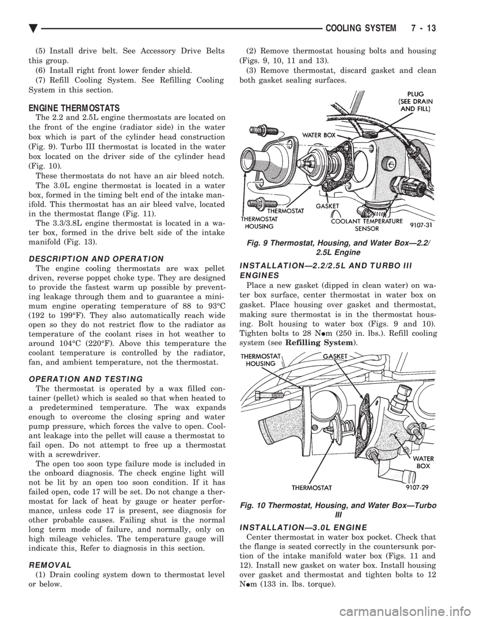
The 2.2 and 2.5L engine thermostats are located on
the front of the engine (radiator side) in the water
box which is part of the cylinder head construction
(Fig. 9). Turbo III thermostat is located in the water
box located on the driver side of the cylinder head
(Fig. 10). These thermostats do not have an air bleed notch.
The 3.0L engine thermostat is located in a water
box, formed in the timing belt end of the intake man-
ifold. This thermostat has an air bleed valve, located
in the thermostat flange (Fig. 11). The 3.3/3.8L engine thermostat is located in a wa-
ter box, formed in the drive belt side of the intake
manifold (Fig. 13).
DESCRIPTION AND OPERATION
The engine cooling thermostats are wax pellet
driven, reverse poppet choke type. They are designed
to provide the fastest warm up possible by prevent-
ing leakage through them and to guarantee a mini-
mum engine operating temperature of 88 to 93ÉC
(192 to 199ÉF). They also automatically reach wide
open so they do not restrict flow to the radiator as
temperature of the coolant rises in hot weather to
around 104ÉC (220ÉF). Above this temperature the
coolant temperature is controlled by the radiator,
fan, and ambient temperature, not the thermostat.
OPERATION AND TESTING
The thermostat is operated by a wax filled con-
tainer (pellet) which is sealed so that when heated to
a predetermined temperature. The wax expands
enough to overcome the closing spring and water
pump pressure, which forces the valve to open. Cool-
ant leakage into the pellet will cause a thermostat to
fail open. Do not attempt to free up a thermostat
with a screwdriver. The open too soon type failure mode is included in
the onboard diagnosis. The check engine light will
not be lit by an open too soon condition. If it has
failed open, code 17 will be set. Do not change a ther-
mostat for lack of heat by gauge or heater perfor-
mance, unless code 17 is present, see diagnosis for
other probable causes. Failing shut is the normal
long term mode of failure, and normally, only on
high mileage vehicles. The temperature gauge will
indicate this, Refer to diagnosis in this section.
REMOVAL
(1) Drain cooling system down to thermostat level
or below. (2) Remove thermostat housing bolts and housing
(Figs. 9, 10, 11 and 13). (3) Remove thermostat, discard gasket and clean
both gasket sealing surfaces.
INSTALLATIONÐ2.2/2.5L AND TURBO III ENGINES
Place a new gasket (dipped in clean water) on wa-
ter box surface, center thermostat in water box on
gasket. Place housing over gasket and thermostat,
making sure thermostat is in the thermostat hous-
ing. Bolt housing to water box (Figs. 9 and 10).
Tighten bolts to 28 N Im (250 in. lbs.). Refill cooling
system (see Refilling System ).
INSTALLATIONÐ3.0L ENGINE
Center thermostat in water box pocket. Check that
the flange is seated correctly in the countersunk por-
tion of the intake manifold water box (Figs. 11 and
12). Install new gasket on water box. Install housing
over gasket and thermostat and tighten bolts to 12
N Im (133 in. lbs. torque).
Fig. 9 Thermostat, Housing, and Water BoxÐ2.2/
2.5L Engine
Fig. 10 Thermostat, Housing, and Water BoxÐTurbo III
Ä COOLING SYSTEM 7 - 13
Page 357 of 2438
-37ÉC (-35ÉF) to -59ÉC (-50ÉF). If it looses color or
becomes contaminated, drain, flush, and replace with
fresh properly mixed solution.
SERVICE
Coolant should be changed at 52,500 miles or three
years, whichever occurs first, then every two years or
30,000 miles.
ROUTINE LEVEL CHECK
Do not remove radiator cap for routine coolant
level inspections. The coolant reserve system provides a quick visual
method for determining the coolant level without re-
moving the radiator cap. Simply observe, with the
engine idling and warmed up to normal operating
temperature, that the level of the coolant in the reserve
tank (Figs. 5 and 6) is between the minimum and
maximum marks.
ADDING ADDITIONAL COOLANT
The radiator cap should not be removed. When
additional coolant is needed to maintain this level, it
should be added to the coolant reserve tank. Use only
50/50 concentration of ethylene glycol type antifreeze
and water.
SERVICE COOLANT LEVEL
The cooling system is closed and designed to main-
tain coolant level to the top of the radiator. When servicing requires a coolant level check in the
radiator, the engine must be offand notunder pres-
sure. Drain several ounces of coolant from the radiator
drain cock while observing the Coolant Recovery Sys-
tem (CRS) Tank. Coolant level in the CRS tank should
drop slightly. Then remove the radiator cap. The radia-
tor should be full to the top. If not, and the coolant level
in the CRS tank is at the MIN mark there is a air leak
in the CRS system. Check hose or hose connections to
the CRS tank, radiator filler neck or the pressure cap
seal to the radiator filler neck for leaks.
LOW COOLANT LEVEL AERATION
Low coolant level in a cross flow radiator will equal-
ize in both tanks with engine off. With engine at
running operating temperature the high pressure inlet
tank runs full and the low pressure outlet tank drops.
If this level drops below the top of the transmission oil
cooler, air will be sucked into the water pump:
² Transmission oil will become hotter.
² High reading shown on the temperature gauge.
² Air in the coolant will also cause loss of flow through
the heater.
² Exhaust gas leaks into the coolant can also cause the
same problems.
DEAERATION
Air can only be removed from the system by gather-
ing under the pressure cap. On the next heat up it will
be pushed past the pressure cap into the CRS tank by
thermal expansion of the coolant. It then escapes to the
atmosphere in the CRS tank and is replaced with solid
coolant on cool down.
COOLING SYSTEM DRAIN, CLEAN, FLUSH AND
REFILL
Drain, flush, and fill the cooling system at the
mileage or time intervals specified in the Maintenance
Schedule in this Group. If the solution is dirty or rusty
or contains a considerable amount of sediment, clean
and flush with a reliable cooling system cleaner. Care
should be taken in disposing of the used engine coolant
from your vehicle. Check governmental regulations for
disposal of used engine coolant.
DRAINING
To drain cooling system move temperature selector
for heater to full heat with engine running (to provide
vacuum for actuation). Without removing radiator
pressure cap and with system not under pres-
sure, Shut engine off and open draincock. The coolant
reserve tank (Fig. 5) should empty first, then remove
radiator pressure cap. (if not, see Testing Cooling
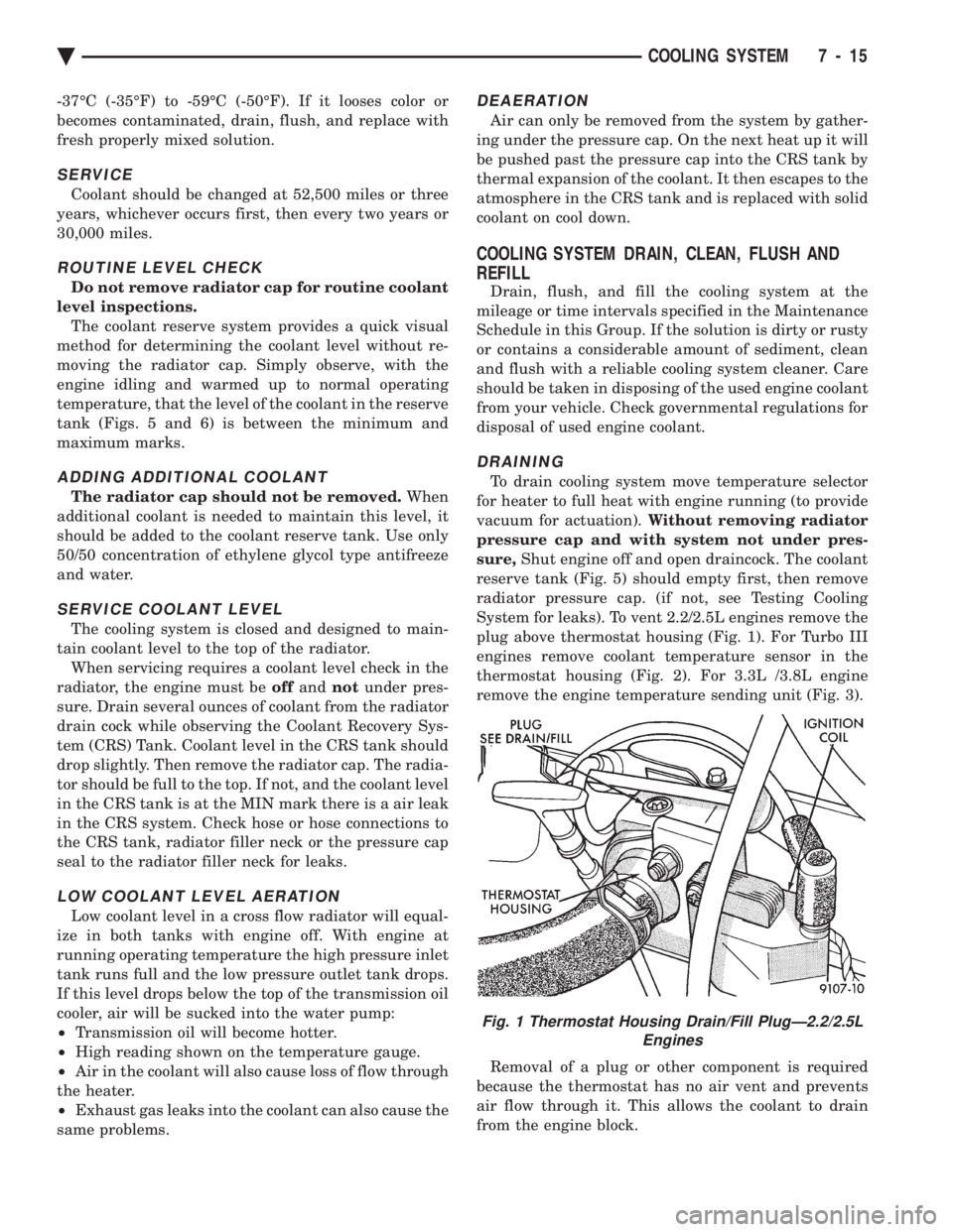
System for leaks). To vent 2.2/2.5L engines remove the
plug above thermostat housing (Fig. 1). For Turbo III
engines remove coolant temperature sensor in the
thermostat housing (Fig. 2). For 3.3L /3.8L engine
remove the engine temperature sending unit (Fig. 3).
Removal of a plug or other component is required
because the thermostat has no air vent and prevents
air flow through it. This allows the coolant to drain
from the engine block.
Fig. 1 Thermostat Housing Drain/Fill PlugÐ2.2/2.5L Engines
Ä COOLING SYSTEM 7 - 15
Page 1992 of 2438
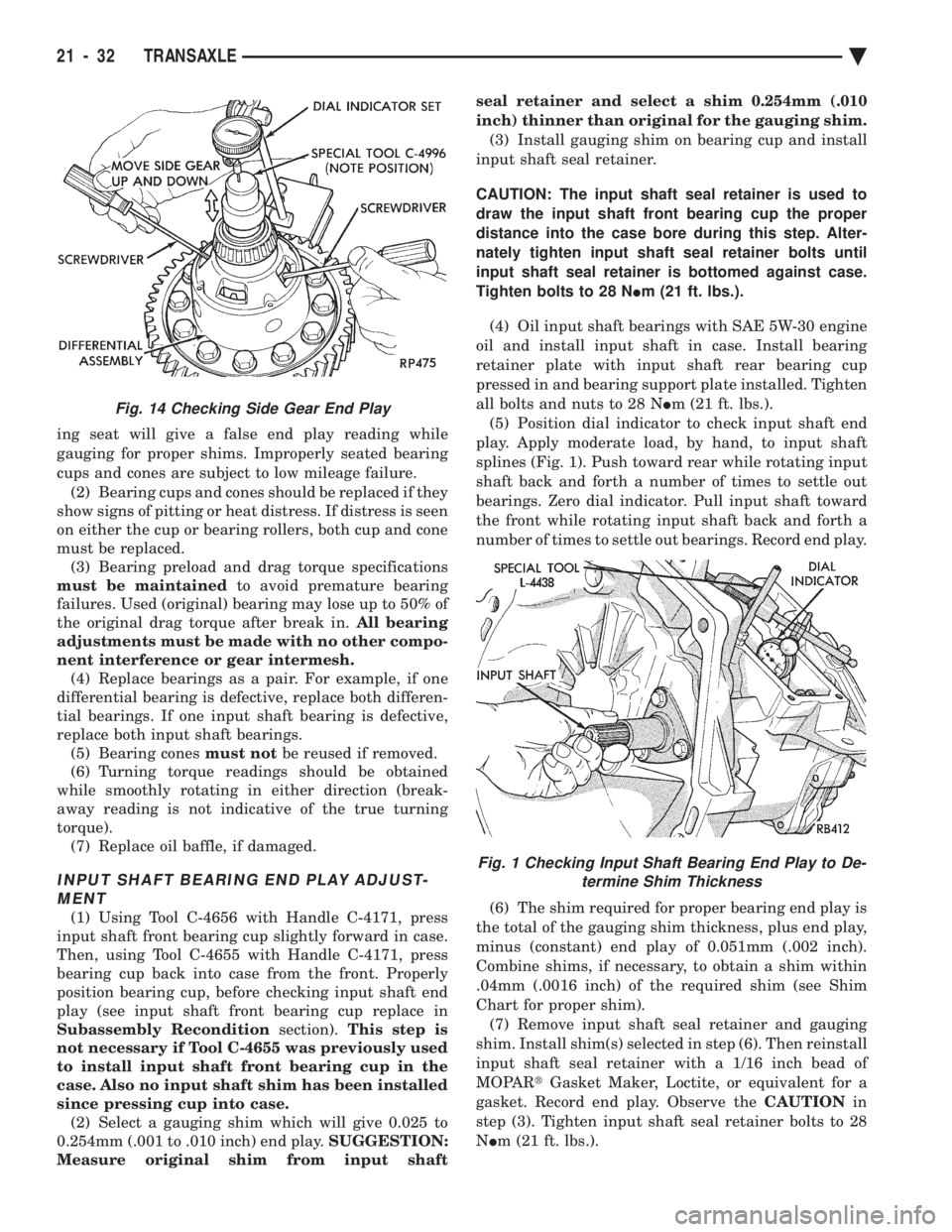
ing seat will give a false end play reading while
gauging for proper shims. Improperly seated bearing
cups and cones are subject to low mileage failure.(2) Bearing cups and cones should be replaced if they
show signs of pitting or heat distress. If distress is seen
on either the cup or bearing rollers, both cup and cone
must be replaced. (3) Bearing preload and drag torque specifications
must be maintained to avoid premature bearing
failures. Used (original) bearing may lose up to 50% of
the original drag torque after break in. All bearing
adjustments must be made with no other compo-
nent interference or gear intermesh. (4) Replace bearings as a pair. For example, if one
differential bearing is defective, replace both differen-
tial bearings. If one input shaft bearing is defective,
replace both input shaft bearings. (5) Bearing cones must notbe reused if removed.
(6) Turning torque readings should be obtained
while smoothly rotating in either direction (break-
away reading is not indicative of the true turning
torque). (7) Replace oil baffle, if damaged.
INPUT SHAFT BEARING END PLAY ADJUST-MENT
(1) Using Tool C-4656 with Handle C-4171, press
input shaft front bearing cup slightly forward in case.
Then, using Tool C-4655 with Handle C-4171, press
bearing cup back into case from the front. Properly
position bearing cup, before checking input shaft end
play (see input shaft front bearing cup replace in
Subassembly Recondition section).This step is
not necessary if Tool C-4655 was previously used
to install input shaft front bearing cup in the
case. Also no input shaft shim has been installed
since pressing cup into case. (2) Select a gauging shim which will give 0.025 to
0.254mm (.001 to .010 inch) end play. SUGGESTION:
Measure original shim from input shaft seal retainer and select a shim 0.254mm (.010
inch) thinner than original for the gauging shim.
(3) Install gauging shim on bearing cup and install
input shaft seal retainer.
CAUTION: The input shaft seal retainer is used to
draw the input shaft front bearing cup the proper
distance into the case bore during this step. Alter-
nately tighten input shaft seal retainer bolts until
input shaft seal retainer is bottomed against case.
Tighten bolts to 28 N Im (21 ft. lbs.).
(4) Oil input shaft bearings with SAE 5W-30 engine
oil and install input shaft in case. Install bearing
retainer plate with input shaft rear bearing cup
pressed in and bearing support plate installed. Tighten
all bolts and nuts to 28 N Im (21 ft. lbs.).
(5) Position dial indicator to check input shaft end
play. Apply moderate load, by hand, to input shaft
splines (Fig. 1). Push toward rear while rotating input
shaft back and forth a number of times to settle out
bearings. Zero dial indicator. Pull input shaft toward
the front while rotating input shaft back and forth a
number of times to settle out bearings. Record end play.
(6) The shim required for proper bearing end play is
the total of the gauging shim thickness, plus end play,
minus (constant) end play of 0.051mm (.002 inch).
Combine shims, if necessary, to obtain a shim within
.04mm (.0016 inch) of the required shim (see Shim
Chart for proper shim). (7) Remove input shaft seal retainer and gauging
shim. Install shim(s) selected in step (6). Then reinstall
input shaft seal retainer with a 1/16 inch bead of
MOPAR tGasket Maker, Loctite, or equivalent for a
gasket. Record end play. Observe the CAUTIONin
step (3). Tighten input shaft seal retainer bolts to 28
N Im (21 ft. lbs.).
Fig. 14 Checking Side Gear End Play
Fig. 1 Checking Input Shaft Bearing End Play to De-
termine Shim Thickness
21 - 32 TRANSAXLE Ä
Page 2149 of 2438
WHEELSÐTIRES
CONTENTS
page page
SPECIFICATIONS ........................ 8
TIRE SERVICE PROCEDURES .............. 1 WHEELS SERVICE PROCEDURES
........... 6
TIRE SERVICE PROCEDURES INDEX
page page
Cleaning of Tires .......................... 1
General Information ........................ 1
Pressure Gauges ......................... 2
Radial-Ply Tires ........................... 1
Repairing Leaks .......................... 3
Rotation ................................ 3 Spare TireÐCompact
...................... 1
Tire Inflation Pressures ..................... 2
Tire Noise or Vibration ..................... 3
Tire Wear Patterns ........................ 3
Tread Wear Indicators ...................... 3
GENERAL INFORMATION
Throughout this group, references may be made to a
particular vehicle by letter or number designation. A
chart showing the breakdown of these designations is
included in the Introduction Section. Tires are designed for the vehicle and provide the
best overall performance for normal operation. The
ride and handling characteristics match the vehicle's
requirements. With proper care they will give excellent
reliability traction, skid resistance and tread life. They
have load carrying capacity, when properly inflated, to
operate at loads up to the specified Maximum Vehicle
Capacity. Driving habits have more effect on tire life than any
other factor. Careful drivers will obtain, in most cases,
much greater mileage than severe or careless drivers. A
few of the driving habits which will shorten the life of
any tire are:
² Rapid acceleration and deceleration
² Severe application of brakes
² High-speed driving
² Taking turns at excessive speeds
² Striking curbs and other obstacles
Radial ply tires can be more susceptible to irregular
tread wear. It is very important to follow the tire
rotation interval shown in the section on Tire
Rotation to achieve a greater tread life potential.
RADIAL-PLY TIRES
Radial-ply tires improve handling, tread life, and
ride quality and decrease rolling resistance. Radial-ply tires must always be used in sets of four
and under no circumstances should they be used on
the front only. However, they may be mixed with temporary spare tires when necessary,
but reduced speeds are recommended. Radial-ply tires have the same load carrying capac-
ity as other types of tires of the same size. They also
use the same recommended inflation pressures.
SPARE TIREÐCOMPACT
The compact spare tire is designed for emergency
use only. The original tire should be repaired and re-
installed at the first opportunity. Refer to Owner's
Manual for complete details.
TIRE CHAINS
Tire snow chains may be used on certainmodels.
Refer to Owner's Manual for more information.
CLEANING OF TIRES
Remove protective coating on tires before delivery
of vehicle, otherwise it could cause deterioration of
tires. Remove protective coating by applying warm wa-
ter, letting it soak one minute, and then scrubbing
the coating away with a soft bristle brush. Steam cleaning may also be used for cleaning.
DO NOT use gasoline or wire brush for cleaning.
DO NOT use mineral oil or an oil-based solvent.
Ä WHEELSÐTIRES 22 - 1