instrument panel CHEVROLET KODIAK 2005 Owner's Guide
[x] Cancel search | Manufacturer: CHEVROLET, Model Year: 2005, Model line: KODIAK, Model: CHEVROLET KODIAK 2005Pages: 374, PDF Size: 5.46 MB
Page 132 of 374
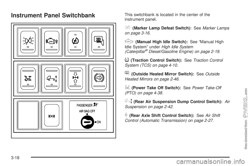
Instrument Panel SwitchbankThis switchbank is located in the center of the
instrument panel.
e(Marker Lamp Defeat Switch):SeeMarker Lamps
on page 3-16.
j(Manual High Idle Switch):See “Manual High
Idle System” underHigh Idle System
(Caterpillar
®Diesel/Gasoline Engine) on page 2-19.
i(Traction Control Switch):SeeTraction Control
System (TCS) on page 4-10.
f(Outside Heated Mirror Switch):SeeOutside
Heated Mirrors on page 2-46.
g(Power Take Off Switch):SeePower Take-Off
(PTO) on page 4-38.
h(Rear Air Suspension Dump Control Switch):Air
Suspension on page 2-42.
k(Rear Axle Shift Control Switch):SeeAir Shift
Control (Automatic Transmission) on page 2-27.
3-18
Page 133 of 374
q(Exhaust Brake Switch):SeeDiesel Engine
Exhaust Brake on page 2-25.
l(Differential Lock Control Switch):SeeRear
Axle Differential Lock Contol on page 4-9.
c(Airbag On/Off Switch):SeeAirbag Off Switch on
page 1-56.
If your vehicle does not have some of the features
controlled by these switches, there will be a blank switch
marker in its place.
Accessory Power Outlets
With accessory power outlets, you can plug in auxiliary
electrical equipment such as a cellular telephone or
CB radio.
The accessory power outlet is located on the
passenger’s side of the instrument panel.
To use an outlet, pull the cover down. When not using
it, always cover the outlet with the protective cap.
This circuit is protected by a fuse and has a maximum
current level.Notice:Leaving electrical equipment on for
extended periods will drain the battery. Always turn
off electrical equipment when not in use and do
not plug in equipment that exceeds the maximum
amperage rating.
Certain electrical accessories may not be compatible
with the accessory power outlet and could result
in blown vehicle or adapter fuses. If you experience a
problem, see your dealer for additional information
on accessory power outlets.
Notice:Adding any electrical equipment to your
vehicle may damage it or keep other components
from working as they should. The repairs would not
be covered by your warranty. Do not use equipment
exceeding maximum amperage rating. Check
with your dealer before adding electrical equipment.
When adding electrical equipment, be sure to follow
the proper installation instructions included with
the equipment.
Notice:Improper use of the power outlet can cause
damage not covered by your warranty. Do not
hang any type of accessory or accessory bracket
from the plug because the power outlets are
designed for accessory power plugs only.
3-19
Page 134 of 374
Ashtrays and Cigarette Lighter
Your vehicle may have an ashtray and a cigarette
lighter located in the center floor console. See
Instrument Panel Overview on page 3-4. To open the
removable ashtray, flip open the top.
Notice:If you put papers, pins, or other �ammable
items in the ashtray, hot cigarettes or other
smoking materials could ignite them and possibly
damage your vehicle. Never put �ammable items in
the ashtray.
To use the cigarette lighter, push it in all the way and let
it go. When it’s ready, it will pop back out by itself.
Notice:Holding a cigarette lighter in while it
is heating will not allow the lighter to back away
from the heating element when it is hot. Damage
from overheating may occur to the lighter or heating
element, or a fuse could be blown. Do not hold a
cigarette lighter in while it is heating.
Climate Controls
Climate Control System
With these systems, you can control the heating,
cooling and ventilation for your vehicle.
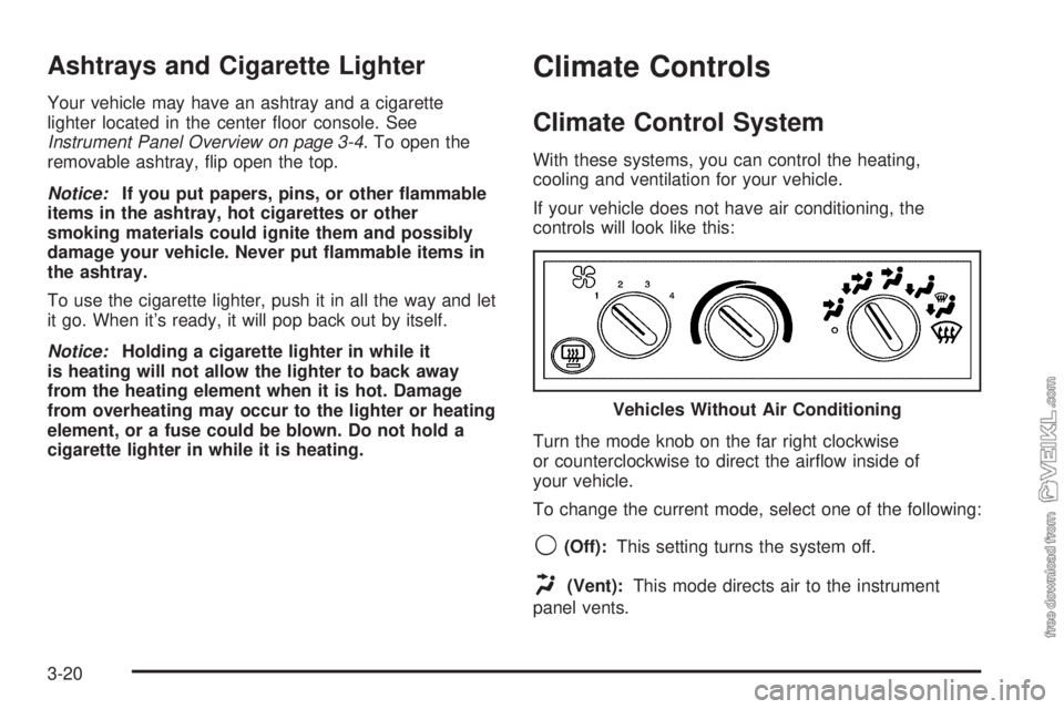
If your vehicle does not have air conditioning, the
controls will look like this:
Turn the mode knob on the far right clockwise
or counterclockwise to direct the airflow inside of
your vehicle.
To change the current mode, select one of the following:
9(Off):This setting turns the system off.
H(Vent):This mode directs air to the instrument
panel vents.Vehicles Without Air Conditioning
3-20
Page 135 of 374
)(Bi-Level):This mode directs half of the air to the
instrument panel vents, then directs the remaining
air to the floor vents. Cooler air is directed to the upper
vents and warmer air to the floor vents.
6(Floor):This mode directs most of the air to the
floor vents. Use this mode to send air to the rear of the
vehicle. Keep the area under the front seats free of
objects that could obstruct airflow to the rear of
the vehicle.
The mode knob can also be used to select the defrost
mode. For more information, see “Defogging and
Defrosting” later in this section.
9(Fan):Turn the left knob clockwise or
counterclockwise to increase or decrease the fan speed.
To increase airflow, turn the knob clockwise. To
decrease airflow, turn it counterclockwise. To turn the
fan off, turn the mode knob on the far right
counterclockwise to the off position.
Temperature Knob:Turn the middle knob located
clockwise or counterclockwise to increase or decrease
the temperature inside of your vehicle. Turn the
knob toward the red area for warmer air. Turn the knob
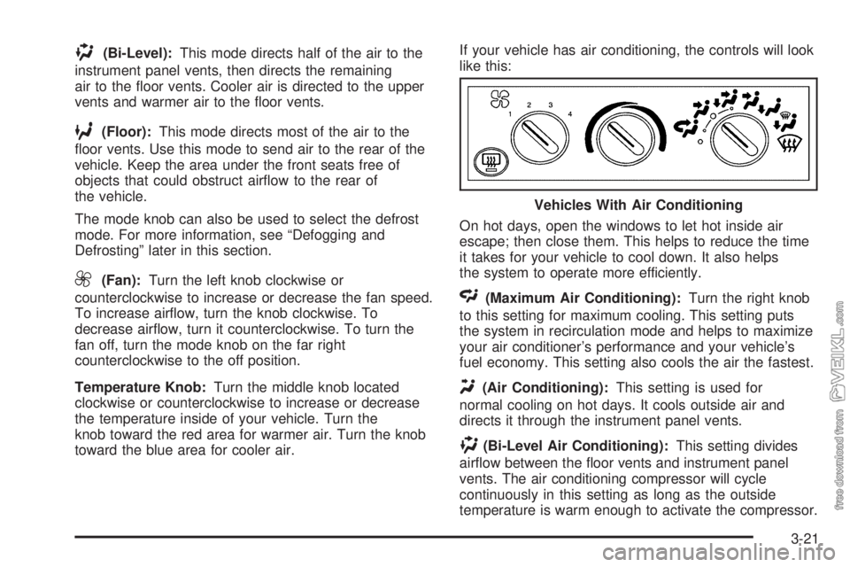
toward the blue area for cooler air.If your vehicle has air conditioning, the controls will look
like this:
On hot days, open the windows to let hot inside air
escape; then close them. This helps to reduce the time
it takes for your vehicle to cool down. It also helps
the system to operate more efficiently.
<(Maximum Air Conditioning):Turn the right knob
to this setting for maximum cooling. This setting puts
the system in recirculation mode and helps to maximize
your air conditioner’s performance and your vehicle’s
fuel economy. This setting also cools the air the fastest.
Y(Air Conditioning):This setting is used for
normal cooling on hot days. It cools outside air and
directs it through the instrument panel vents.
)(Bi-Level Air Conditioning):This setting divides
airflow between the floor vents and instrument panel
vents. The air conditioning compressor will cycle
continuously in this setting as long as the outside
temperature is warm enough to activate the compressor.Vehicles With Air Conditioning
3-21
Page 137 of 374
The rear window defogger will turn off several minutes
after the button is pressed. The defogger can also
be turned off by pressing the button again or by turning
off the engine.
Notice:Do not use anything sharp on the inside of
the rear window. If you do, you could cut or
damage the warming grid, and the repairs would not
be covered by your warranty. Do not attach a
temporary vehicle license, tape, a decal or anything
similar to the defogger grid.
Outlet Adjustment
Your vehicle has air outlets on the instrument panel that
allow you to adjust the direction and amount of airflow
inside the vehicle.
Move the lever on the outlet up or down to direct the
airflow. Increase or reduce the amount of airflow
by opening and closing the louvers. The outlets can be
moved side-to-side to direct the airflow.
Operation Tips
•
Keep the hood and front air inlets free of ice, snow,
or any other obstruction (such as leaves). The
heater and defroster will work far better, reducing
the chance of fogging the inside of your windows.
•Keep the air path under the front seats clear
of objects. This helps air to circulate throughout your
vehicle.
•Adding outside equipment to the front of your
vehicle, such as hood-air deflectors, may affect the
performance of the heating and air conditioning
system. Check with your dealer before adding
equipment to the outside of your vehicle.
3-23
Page 139 of 374
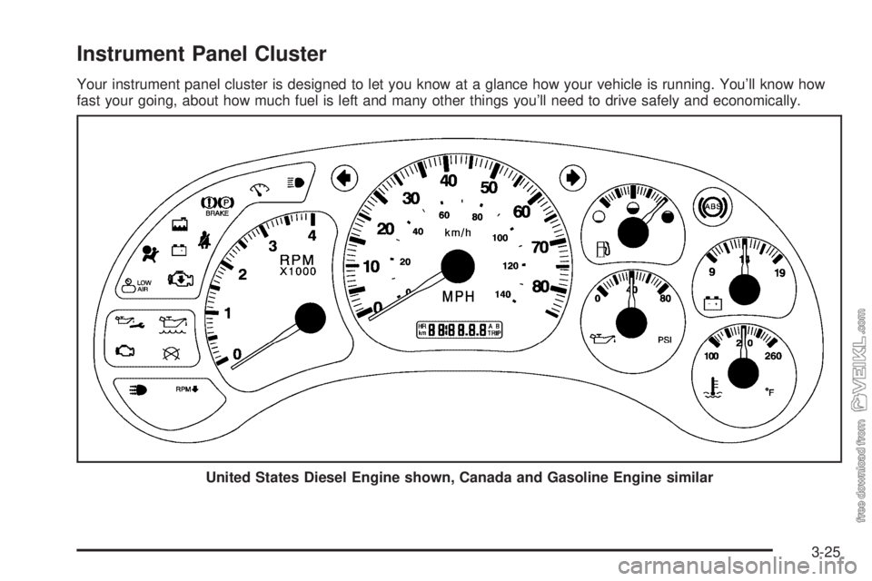
Instrument Panel Cluster
Your instrument panel cluster is designed to let you know at a glance how your vehicle is running. You’ll know how
fast your going, about how much fuel is left and many other things you’ll need to drive safely and economically.
United States Diesel Engine shown, Canada and Gasoline Engine similar
3-25
Page 141 of 374
Engine Road Speed Governor
This system controls maximum vehicle speed
automatically and reduces engine power until vehicle
speed gets down to maximum governed speed.
The default setting for C4500 and C5500 models up to
19,500 lbs GVWR is 80 to 85 mph (128 to 136 km/h).
Most other models have a default setting of 75 mph
(120 km/h), although some tire sizes and tread patterns
may limit maximum speed to 55 to 65 mph
(86 to 105 km/h). You may have a label on the headliner
of your vehicle with more information on your engine road
speed governor. See your GM dealer for assistance with
programming your engine limited speed.
Safety Belt Reminder Light
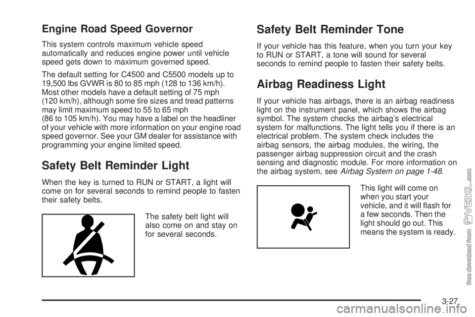
When the key is turned to RUN or START, a light will
come on for several seconds to remind people to fasten
their safety belts.
The safety belt light will
also come on and stay on
for several seconds.
Safety Belt Reminder Tone
If your vehicle has this feature, when you turn your key
to RUN or START, a tone will sound for several
seconds to remind people to fasten their safety belts.
Airbag Readiness Light
If your vehicle has airbags, there is an airbag readiness
light on the instrument panel, which shows the airbag
symbol. The system checks the airbag’s electrical
system for malfunctions. The light tells you if there is an
electrical problem. The system check includes the
airbag sensors, the airbag modules, the wiring, the
passenger airbag suppression circuit and the crash
sensing and diagnostic module. For more information on
the airbag system, seeAirbag System on page 1-48.
This light will come on
when you start your
vehicle, and it will flash for
a few seconds. Then the
light should go out. This
means the system is ready.
3-27
Page 144 of 374
Charging System Light
The charging system light
may be located in the
instrument panel cluster, or
with the auxiliary warning
lights in the center of
the instrument panel.
It should come on briefly when you turn on the ignition,
before the engine is running, as a check to show
that it is working.
If it stays on, or comes on while you are driving, have
your vehicle checked right away. You could have a loose
generator drive belt or some other problem.
Driving while this light is on will drain your battery. If you
must drive a short distance with the light on, turn off
your radio and other accessories. Sustained driving with
a generator failure could result in a lack of back-up
braking if the engine quits or the power steering pump
should fail.
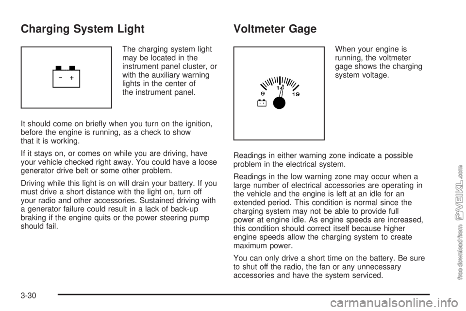
Voltmeter Gage
When your engine is
running, the voltmeter
gage shows the charging
system voltage.
Readings in either warning zone indicate a possible
problem in the electrical system.
Readings in the low warning zone may occur when a
large number of electrical accessories are operating in
the vehicle and the engine is left at an idle for an
extended period. This condition is normal since the
charging system may not be able to provide full
power at engine idle. As engine speeds are increased,
this condition should correct itself because higher
engine speeds allow the charging system to create
maximum power.
You can only drive a short time on the battery. Be sure
to shut off the radio, the fan or any unnecessary
accessories and have the system serviced.
3-30
Page 145 of 374
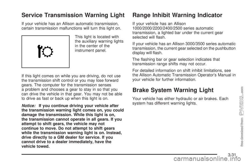
Service Transmission Warning Light
If your vehicle has an Allison automatic transmission,
certain transmission malfunctions will turn this light on.
This light is located with
the auxiliary warning lights
in the center of the
instrument panel.
If this light comes on while you are driving, do not use
the transmission shift control or you may lose forward
gears. The computer for the transmission senses
a problem and chooses a gear to stay in so that you
can drive the vehicle in that gear. You may not be able
to drive as fast or back up when this light is on.
Notice:If you continue driving your vehicle after
the transmission warning light comes on, you could
damage the transmission. While this light is on,
the transmission cannot operate in all gears. If you
attempt to shift gears, the vehicle may not
continue to move. Do not attempt to shift gears
while the transmission warning light is on. Instead,
drive directly to a GM dealer for service. If you
cannot drive to a dealer immediately, have the
vehicle towed.
Range Inhibit Warning Indicator
If your vehicle has an Allison
1000/2000/2200/2400/2500 series automatic
transmission, a lighted bar under the current gear
selected will flash.
If your vehicle has an Allison 3000/3500 series automatic
transmission, the current gear selected on the pushbutton
display will flash.
The flashing bar or gear selection indicates that
transmission range shifts may not occur.
For detailed information on shift inhibit limitations, see
the Allison Automatic Transmission Operator’s Manual in
your vehicle for further information.
Brake System Warning Light
Your vehicle has either hydraulic or air brakes. Each
system has different warning lights.
3-31
Page 146 of 374
Hydraulic Brake System
Warning Lights
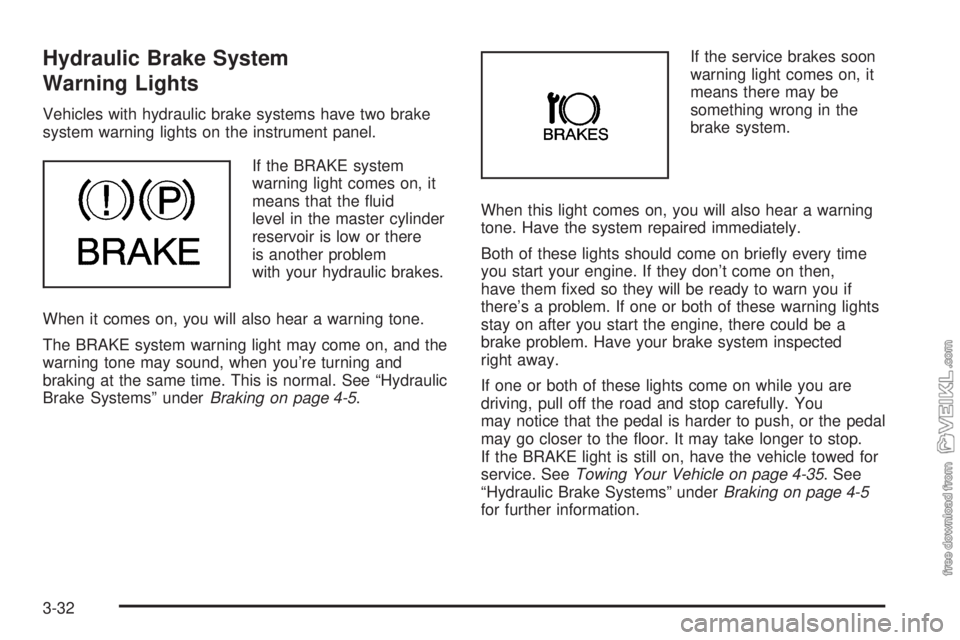
Vehicles with hydraulic brake systems have two brake
system warning lights on the instrument panel.
If the BRAKE system
warning light comes on, it
means that the fluid
level in the master cylinder
reservoir is low or there
is another problem
with your hydraulic brakes.
When it comes on, you will also hear a warning tone.
The BRAKE system warning light may come on, and the
warning tone may sound, when you’re turning and
braking at the same time. This is normal. See “Hydraulic
Brake Systems” underBraking on page 4-5.If the service brakes soon
warning light comes on, it
means there may be
something wrong in the
brake system.
When this light comes on, you will also hear a warning
tone. Have the system repaired immediately.
Both of these lights should come on briefly every time
you start your engine. If they don’t come on then,
have them fixed so they will be ready to warn you if
there’s a problem. If one or both of these warning lights
stay on after you start the engine, there could be a
brake problem. Have your brake system inspected
right away.
If one or both of these lights come on while you are
driving, pull off the road and stop carefully. You
may notice that the pedal is harder to push, or the pedal
may go closer to the floor. It may take longer to stop.
If the BRAKE light is still on, have the vehicle towed for
service. SeeTowing Your Vehicle on page 4-35. See
“Hydraulic Brake Systems” underBraking on page 4-5
for further information.
3-32