lock CHEVROLET PLYMOUTH ACCLAIM 1993 Service Manual
[x] Cancel search | Manufacturer: CHEVROLET, Model Year: 1993, Model line: PLYMOUTH ACCLAIM, Model: CHEVROLET PLYMOUTH ACCLAIM 1993Pages: 2438, PDF Size: 74.98 MB
Page 2212 of 2438
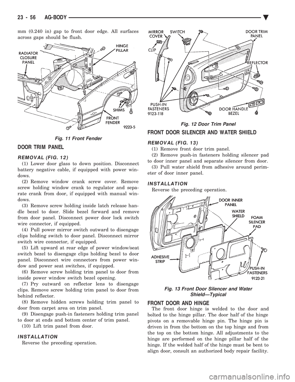
mm (0.240 in) gap to front door edge. All surfaces
across gaps should be flush.
DOOR TRIM PANEL
REMOVAL (FIG. 12)
(1) Lower door glass to down position. Disconnect
battery negative cable, if equipped with power win-
dows. (2) Remove window crank screw cover. Remove
screw holding window crank to regulator and sepa-
rate crank from door, if equipped with manual win-
dows. (3) Remove screw holding inside latch release han-
dle bezel to door. Slide bezel forward and remove
from door panel. Disconnect power door lock switch
wire connector, if equipped. (4) Pull power mirror switch outward to disengage
clips holding switch to door panel. Disconnect mirror
switch wire connector, if equipped. (5) Lift upward at rear edge of power window/seat
switch bezel to disengage clips holding bezel to door
panel. Disconnect wire connectors from power win-
dow and power seat switches, if equipped. (6) Remove screw holding trim panel to door from
inside power window switch bezel opening. (7) Pry outward on reflector lens to disengage
clips. Remove screw holding trim panel to door from
behind reflector. (8) Remove hidden screws holding trim panel to
door from carpet area on trim panel. (9) Disengage push-in fasteners holding trim panel
to door at ends and bottom center of trim panel. (10) Lift trim panel from door.
INSTALLATION
Reverse the preceding operation.
FRONT DOOR SILENCER AND WATER SHIELD
REMOVAL (FIG. 13)
(1) Remove front door trim panel.
(2) Remove push-in fasteners holding silencer pad
to door inner panel and separate silencer from door. (3) Pull water shield from adhesive around perim-
eter of door inner panel.
INSTALLATION
Reverse the preceding operation.
FRONT DOOR AND HINGE
The front door hinge is welded to the door and
bolted to the hinge pillar. The door half of the hinge
pivots on a removable hinge pin. The hinge pin is
driven in from the bottom on the top hinge and from
the top on the bottom hinge. All adjustments to the
hinge are performed on the hinge pillar half of the
hinge. If the welded half of the hinge must be bent to
align door, consult an authorized body repair facility.
Fig. 11 Front Fender
Fig. 12 Door Trim Panel
Fig. 13 Front Door Silencer and Water ShieldÐTypical
23 - 56 AG-BODY Ä
Page 2214 of 2438
MANUAL WINDOW REGULATOR
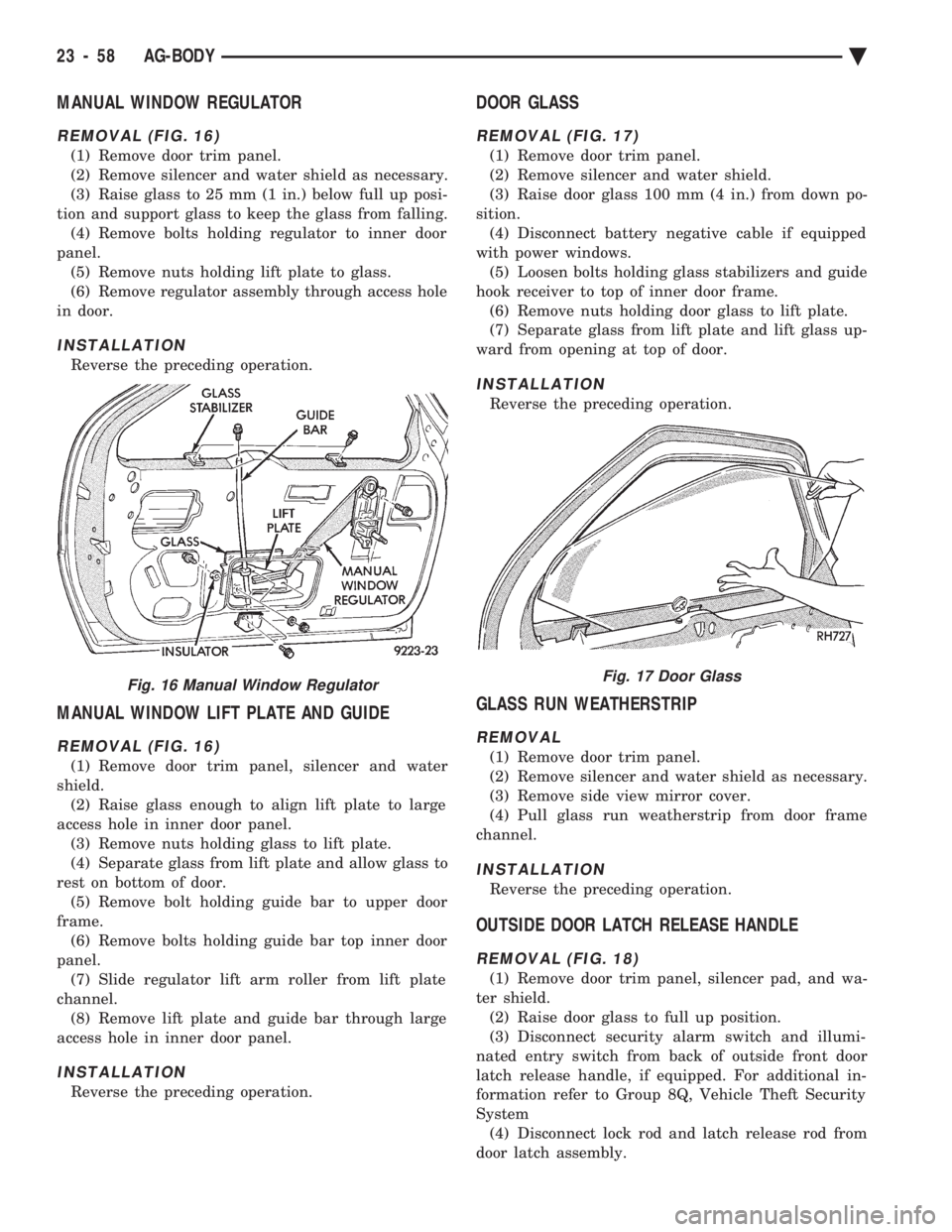
REMOVAL (FIG. 16)
(1) Remove door trim panel.
(2) Remove silencer and water shield as necessary.
(3) Raise glass to 25 mm (1 in.) below full up posi-
tion and support glass to keep the glass from falling. (4) Remove bolts holding regulator to inner door
panel. (5) Remove nuts holding lift plate to glass.
(6) Remove regulator assembly through access hole
in door.
INSTALLATION
Reverse the preceding operation.
MANUAL WINDOW LIFT PLATE AND GUIDE
REMOVAL (FIG. 16)
(1) Remove door trim panel, silencer and water
shield. (2) Raise glass enough to align lift plate to large
access hole in inner door panel. (3) Remove nuts holding glass to lift plate.
(4) Separate glass from lift plate and allow glass to
rest on bottom of door. (5) Remove bolt holding guide bar to upper door
frame. (6) Remove bolts holding guide bar top inner door
panel. (7) Slide regulator lift arm roller from lift plate
channel. (8) Remove lift plate and guide bar through large
access hole in inner door panel.
INSTALLATION
Reverse the preceding operation.
DOOR GLASS
REMOVAL (FIG. 17)
(1) Remove door trim panel.
(2) Remove silencer and water shield.
(3) Raise door glass 100 mm (4 in.) from down po-
sition. (4) Disconnect battery negative cable if equipped
with power windows. (5) Loosen bolts holding glass stabilizers and guide
hook receiver to top of inner door frame. (6) Remove nuts holding door glass to lift plate.
(7) Separate glass from lift plate and lift glass up-
ward from opening at top of door.
INSTALLATION
Reverse the preceding operation.
GLASS RUN WEATHERSTRIP
REMOVAL
(1) Remove door trim panel.
(2) Remove silencer and water shield as necessary.
(3) Remove side view mirror cover.
(4) Pull glass run weatherstrip from door frame
channel.
INSTALLATION
Reverse the preceding operation.
OUTSIDE DOOR LATCH RELEASE HANDLE
REMOVAL (FIG. 18)
(1) Remove door trim panel, silencer pad, and wa-
ter shield. (2) Raise door glass to full up position.
(3) Disconnect security alarm switch and illumi-
nated entry switch from back of outside front door
latch release handle, if equipped. For additional in-
formation refer to Group 8Q, Vehicle Theft Security
System (4) Disconnect lock rod and latch release rod from
door latch assembly.
Fig. 16 Manual Window RegulatorFig. 17 Door Glass
23 - 58 AG-BODY Ä
Page 2215 of 2438
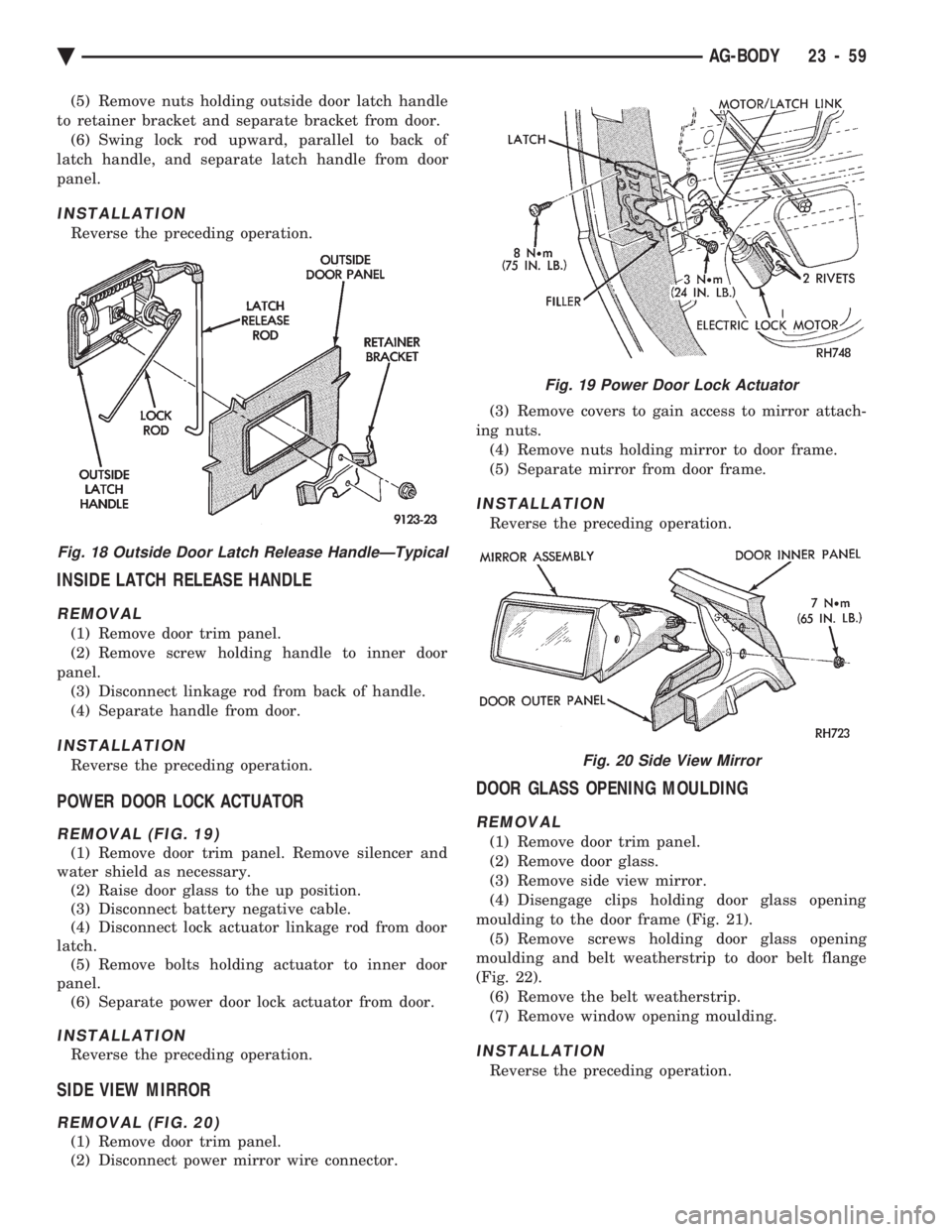
(5) Remove nuts holding outside door latch handle
to retainer bracket and separate bracket from door. (6) Swing lock rod upward, parallel to back of
latch handle, and separate latch handle from door
panel.
INSTALLATION
Reverse the preceding operation.
INSIDE LATCH RELEASE HANDLE
REMOVAL
(1) Remove door trim panel.
(2) Remove screw holding handle to inner door
panel. (3) Disconnect linkage rod from back of handle.
(4) Separate handle from door.
INSTALLATION
Reverse the preceding operation.
POWER DOOR LOCK ACTUATOR
REMOVAL (FIG. 19)
(1) Remove door trim panel. Remove silencer and
water shield as necessary. (2) Raise door glass to the up position.
(3) Disconnect battery negative cable.
(4) Disconnect lock actuator linkage rod from door
latch. (5) Remove bolts holding actuator to inner door
panel. (6) Separate power door lock actuator from door.
INSTALLATION
Reverse the preceding operation.
SIDE VIEW MIRROR
REMOVAL (FIG. 20)
(1) Remove door trim panel.
(2) Disconnect power mirror wire connector. (3) Remove covers to gain access to mirror attach-
ing nuts. (4) Remove nuts holding mirror to door frame.
(5) Separate mirror from door frame.
INSTALLATION
Reverse the preceding operation.
DOOR GLASS OPENING MOULDING
REMOVAL
(1) Remove door trim panel.
(2) Remove door glass.
(3) Remove side view mirror.
(4) Disengage clips holding door glass opening
moulding to the door frame (Fig. 21). (5) Remove screws holding door glass opening
moulding and belt weatherstrip to door belt flange
(Fig. 22). (6) Remove the belt weatherstrip.
(7) Remove window opening moulding.
INSTALLATION
Reverse the preceding operation.
Fig. 18 Outside Door Latch Release HandleÐTypical
Fig. 19 Power Door Lock Actuator
Fig. 20 Side View Mirror
Ä AG-BODY 23 - 59
Page 2224 of 2438
(3) Disconnect lift gate wire connectors and rear
window washer hose, if equipped. (4) Remove upper lift gate trim molding.
(5) Support lift gate on a suitable lifting device.
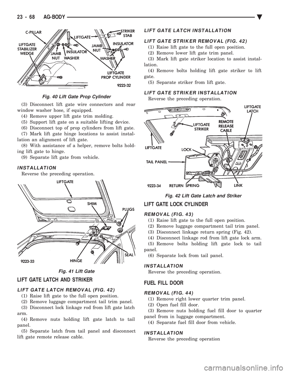
(6) Disconnect top of prop cylinders from lift gate.
(7) Mark lift gate hinge locations to assist instal-
lation an alignment of lift gate. (8) With assistance of a helper, remove bolts hold-
ing lift gate to hinge. (9) Separate lift gate from vehicle.
INSTALLATION
Reverse the preceding operation.
LIFT GATE LATCH AND STRIKER
LIFT GATE LATCH REMOVAL (FIG. 42)
(1) Raise lift gate to the full open position.
(2) Remove luggage compartment tail trim panel.
(3) Disconnect lock linkage rod from lift gate latch
arm. (4) Remove nuts holding lift gate latch to tail
panel. (5) Separate latch from tail panel and disconnect
lift gate remote release cable.
LIFT GATE LATCH INSTALLATION
LIFT GATE STRIKER REMOVAL (FIG. 42)
(1) Raise lift gate to the full open position.
(2) Remove lower lift gate trim panel.
(3) Mark lift gate striker location to assist instal-
lation. (4) Remove bolts holding lift gate striker to lift
gate. (5) Separate striker from lift gate.
LIFT GATE STRIKER INSTALLATION
Reverse the preceding operation.
LIFT GATE LOCK CYLINDER
REMOVAL (FIG. 43)
(1) Raise lift gate to the full open position.
(2) Remove luggage compartment tail trim panel.
(3) Disconnect linkage return spring (Fig. 42).
(4) Disconnect linkage rod from lift gate lock arm.
(5) Remove bolts holding lift gate lock to tail
panel. (6) Separate lock from tail panel.
INSTALLATION
Reverse the preceding operation.
FUEL FILL DOOR
REMOVAL (FIG. 44)
(1) Remove right lower quarter trim panel.
(2) Open fuel fill door.
(3) Remove nuts holding fuel fill door to quarter
panel from in luggage compartment. (4) Separate fuel fill door from vehicle.
INSTALLATION
Reverse the preceding operation
Fig. 40 Lift Gate Prop Cylinder
Fig. 41 Lift Gate
Fig. 42 Lift Gate Latch and Striker
23 - 68 AG-BODY Ä
Page 2225 of 2438
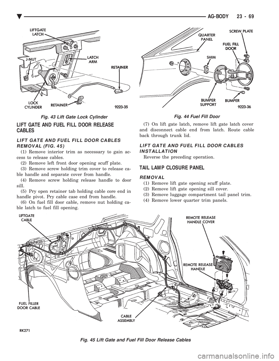
LIFT GATE AND FUEL FILL DOOR RELEASE
CABLES
LIFT GATE AND FUEL FILL DOOR CABLES
REMOVAL (FIG. 45)
(1) Remove interior trim as necessary to gain ac-
cess to release cables. (2) Remove left front door opening scuff plate.
(3) Remove screw holding trim cover to release ca-
ble handle and separate cover from handle. (4) Remove screw holding release handle to door
sill. (5) Pry open retainer tab holding cable core end in
handle pivot. Pry cable case end from handle. (6) On fuel fill door cable, remove nut holding ca-
ble latch to fuel fill opening. (7) On lift gate latch, remove lift gate latch cover
and disconnect cable end from latch. Route cable
back through trunk lid.
LIFT GATE AND FUEL FILL DOOR CABLES INSTALLATION
Reverse the preceding operation.
TAIL LAMP CLOSURE PANEL
REMOVAL
(1) Remove lift gate opening scuff plate.
(2) Remove lift gate opening sill cover.
(3) Remove luggage compartment tail panel trim.
(4) Remove lower quarter trim panels.
Fig. 45 Lift Gate and Fuel Fill Door Release Cables
Fig. 43 Lift Gate Lock CylinderFig. 44 Fuel Fill Door
Ä AG-BODY 23 - 69
Page 2227 of 2438
AJ-VEHICLE BODY COMPONENT SERVICE INDEX
page page
A-Pillar and Roof Rail Mouldings ............. 77
Cowl Cover ............................. 73
Cowl Panel Trim and Scuff Plates ............ 77
Door Glass ............................. 76
Door Glass Lift Plate and Guide Post ......... 76
Door Latch ............................. 75
Door Trim Panel ......................... 74
Floor Carpet ............................ 80
Front Center Console ..................... 79
Front Door and Hinge ..................... 75
Front Door Silencer and Water Shield ......... 74
Front End Splash Shields .................. 73
Front Seat Belts ......................... 78
Front Seats ............................. 78
Fuel Fill Door ........................... 84
Glass Run WeatherstripÐAJ-21 Body ......... 76
Grille .................................. 71
Grille Header Molding ..................... 71
Grille Opening Panel ...................... 71
Head Lining ............................. 81
Hood and Hinges ........................ 72
Hood Latch and Release Cable .............. 72
Inside Latch Release Handle ................ 76 Lower Grille
............................. 71
Outside Door Latch Release Handle .......... 76
Overhead Console ........................ 80
Power Door Lock Actuator .................. 76
Quarter Extension Trim Panel ............... 77
Quarter Glass Module ..................... 85
Quarter Trim Panel ....................... 77
Rear Seat Belts .......................... 78
Rear Seats ............................. 79
Rear Shelf Trim Panel ..................... 78
Rear Window Glass ...................... 81
Sun Roof Air Deflector .................... 81
Sun Roof Drain Tubes .................... 81
Sun Roof Weatherstrip .................... 81
Trunk Lid .............................. 82
Trunk Lid and Fuel Fill Door Release Cables . . . 83
Trunk Lid Hinge ......................... 82
Trunk Lid Latch .......................... 83
Trunk Lid Lock .......................... 83
Trunk Lid Luggage Rack ................... 83
Trunk Lid Torsion Bar ..................... 83
Trunk Opening Weatherstrip ................ 83
Window Regulator ........................ 75
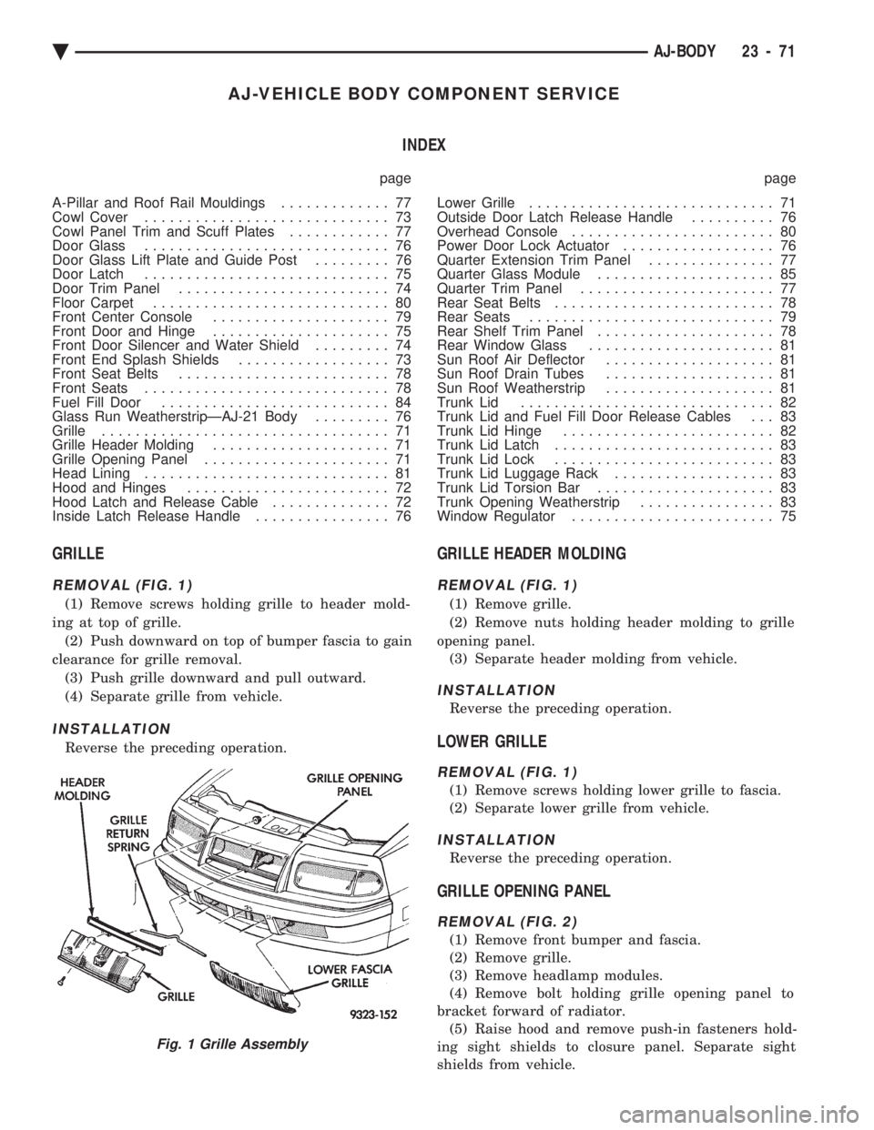
GRILLE
REMOVAL (FIG. 1)
(1) Remove screws holding grille to header mold-
ing at top of grille. (2) Push downward on top of bumper fascia to gain
clearance for grille removal. (3) Push grille downward and pull outward.
(4) Separate grille from vehicle.
INSTALLATION
Reverse the preceding operation.
GRILLE HEADER MOLDING
REMOVAL (FIG. 1)
(1) Remove grille.
(2) Remove nuts holding header molding to grille
opening panel. (3) Separate header molding from vehicle.
INSTALLATION
Reverse the preceding operation.
LOWER GRILLE
REMOVAL (FIG. 1)
(1) Remove screws holding lower grille to fascia.
(2) Separate lower grille from vehicle.
INSTALLATION
Reverse the preceding operation.
GRILLE OPENING PANEL
REMOVAL (FIG. 2)
(1) Remove front bumper and fascia.
(2) Remove grille.
(3) Remove headlamp modules.
(4) Remove bolt holding grille opening panel to
bracket forward of radiator. (5) Raise hood and remove push-in fasteners hold-
ing sight shields to closure panel. Separate sight
shields from vehicle.
Fig. 1 Grille Assembly
Ä AJ-BODY 23 - 71
Page 2230 of 2438
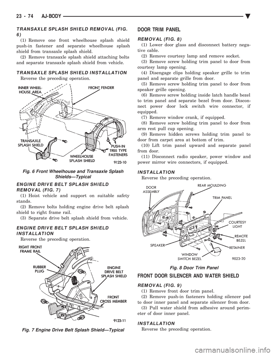
TRANSAXLE SPLASH SHIELD REMOVAL (FIG. 6)
(1) Remove one front wheelhouse splash shield
push-in fastener and separate wheelhouse splash
shield from transaxle splash shield. (2) Remove transaxle splash shield attaching bolts
and separate transaxle splash shield from vehicle.
TRANSAXLE SPLASH SHIELD INSTALLATION
Reverse the preceding operation.
ENGINE DRIVE BELT SPLASH SHIELD REMOVAL (FIG. 7)
(1) Hoist vehicle and support on suitable safety
stands. (2) Remove bolts holding engine drive belt splash
shield to right frame rail. (3) Separate drive belt splash shield from vehicle.
ENGINE DRIVE BELT SPLASH SHIELDINSTALLATION
Reverse the preceding operation.
DOOR TRIM PANEL
REMOVAL (FIG. 8)
(1) Lower door glass and disconnect battery nega-
tive cable. (2) Remove courtesy lamp and remove socket.
(3) Remove screw holding trim panel to door from
courtesy lamp opening. (4) Disengage clips holding speaker grille to trim
panel and separate grille from door. (5) Remove screw holding trim panel to door from
speaker grille opening. (6) Remove screw holding inside latch handle bezel
to trim panel and separate bezel from door. Discon-
nect power door lock switch wire connector, if
equipped. (7) Remove window crank, if equipped.
(8) Remove screw holding trim panel to door from
arm rest pull cup opening. (9) Remove hidden screws holding trim panel to
door from carpet area at bottom of trim. (10) Lift trim panel upward and separate panel
from door. (11) Disconnect radio speaker, power window and
power mirror wire connectors, if equipped.
INSTALLATION
Reverse the preceding operation.
FRONT DOOR SILENCER AND WATER SHIELD
REMOVAL (FIG. 9)
(1) Remove front door trim panel.
(2) Remove push-in fasteners holding silencer pad
to door inner panel and separate silencer from door. (3) Pull water shield from adhesive around perim-
eter of door inner panel.
INSTALLATION
Reverse the preceding operation.
Fig. 6 Front Wheelhouse and Transaxle Splash ShieldsÐTypical
Fig. 7 Engine Drive Belt Splash ShieldÐTypical
Fig. 8 Door Trim Panel
23 - 74 AJ-BODY Ä
Page 2232 of 2438
DOOR GLASS
REMOVAL
(1) Remove door trim panel.
(2) Remove silencer and water shield.
(3) Raise door glass 100 mm (4 in.) from down po-
sition. (4) Disconnect battery negative cable if equipped
with power windows. (5) Loosen bolts holding glass stabilizers and guide
hook receiver to top of inner door frame. (6) Remove nuts holding door glass to lift plate.
(7) Separate glass from lift plate and lift glass up-
ward from opening at top of door.
INSTALLATION
Reverse the preceding operation.
DOOR GLASS LIFT PLATE AND GUIDE POST
REMOVAL
(1) Remove door trim panel.
(2) Remove silencer and water shield.
(3) Raise door glass 100 mm (4 in.) from down po-
sition. (4) Disconnect battery negative cable if equipped
with power windows. (5) Remove nuts holding door glass to lift plate
and separate glass from lift plate. Allow glass to
slide downward to the bottom of door. (6) Remove bolts (nuts on AJ-27 body) holding
guide post to inner door panel. (7) Separate lift plate channel from regulator lift
roller. (8) Remove lift plate and guide assemble from door
through access hole in inner door panel.
INSTALLATION
Reverse the preceding operation.
GLASS RUN WEATHERSTRIPÐAJ-21 BODY
REMOVAL
(1) Remove door trim panel.
(2) Remove silencer and water shield as necessary.
(3) Remove side view mirror cover.
(4) Pull glass run weatherstrip from door frame
channel.
INSTALLATION
Reverse the preceding operation.
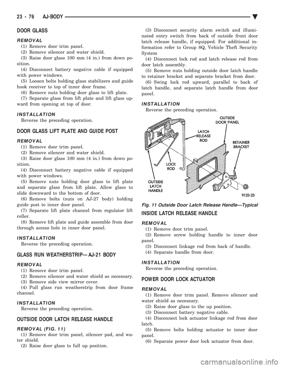
OUTSIDE DOOR LATCH RELEASE HANDLE
REMOVAL (FIG. 11)
(1) Remove door trim panel, silencer pad, and wa-
ter shield. (2) Raise door glass to full up position. (3) Disconnect security alarm switch and illumi-
nated entry switch from back of outside front door
latch release handle, if equipped. For additional in-
formation refer to Group 8Q, Vehicle Theft Security
System (4) Disconnect lock rod and latch release rod from
door latch assembly. (5) Remove nuts holding outside door latch handle
to retainer bracket and separate bracket from door. (6) Swing lock rod upward, parallel to back of
latch handle, and separate latch handle from door
panel.
INSTALLATION
Reverse the preceding operation.
INSIDE LATCH RELEASE HANDLE
REMOVAL
(1) Remove door trim panel.
(2) Remove screw holding handle to inner door
panel. (3) Disconnect linkage rod from back of handle.
(4) Separate handle from door.
INSTALLATION
Reverse the preceding operation.
POWER DOOR LOCK ACTUATOR
REMOVAL
(1) Remove door trim panel. Remove silencer and
water shield as necessary. (2) Raise door glass to the up position.
(3) Disconnect battery negative cable.
(4) Disconnect lock actuator linkage rod from door
latch. (5) Remove bolts holding actuator to inner door
panel. (6) Separate power door lock actuator from door.
Fig. 11 Outside Door Latch Release HandleÐTypical
23 - 76 AJ-BODY Ä
Page 2239 of 2438
TRUNK LID TORSION BAR
REMOVAL
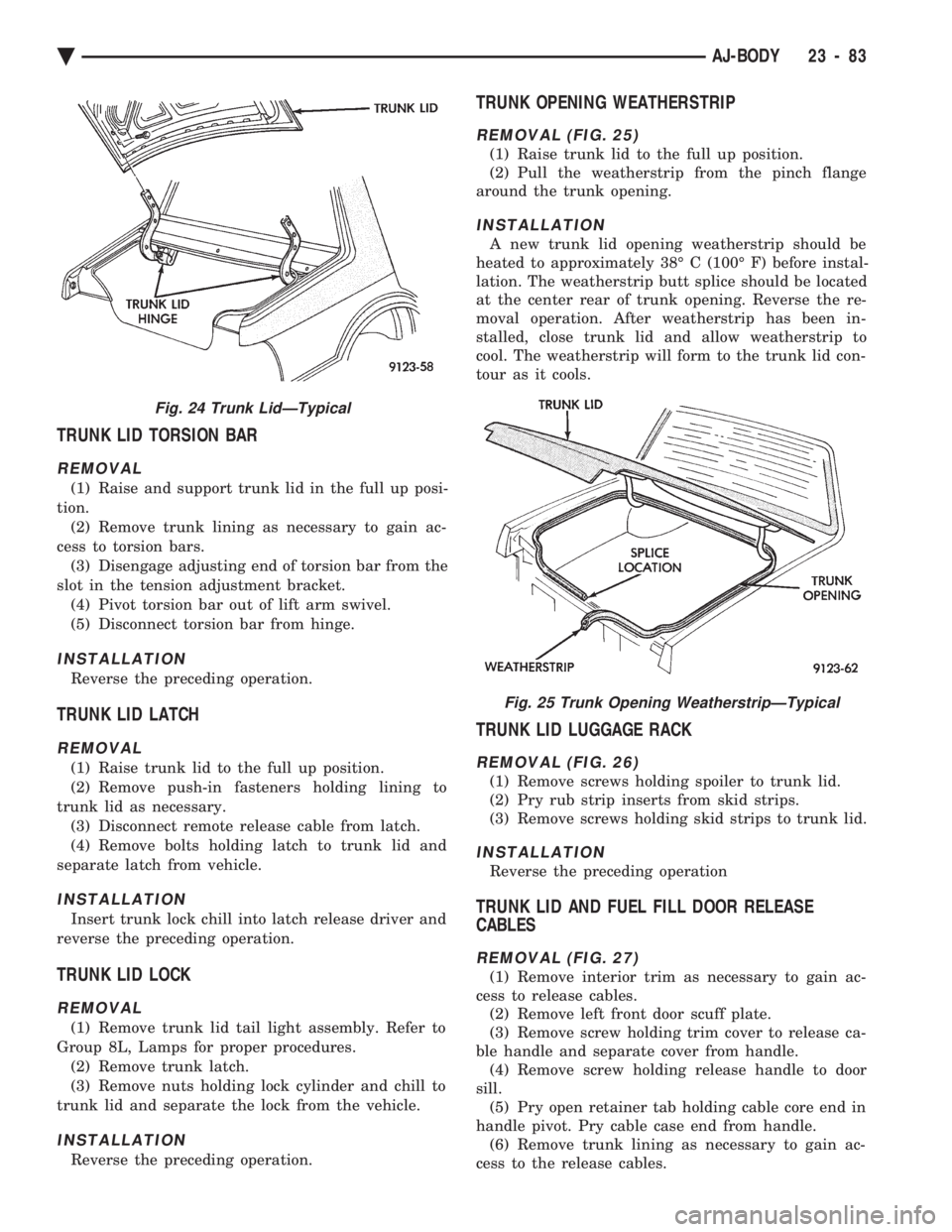
(1) Raise and support trunk lid in the full up posi-
tion. (2) Remove trunk lining as necessary to gain ac-
cess to torsion bars. (3) Disengage adjusting end of torsion bar from the
slot in the tension adjustment bracket. (4) Pivot torsion bar out of lift arm swivel.
(5) Disconnect torsion bar from hinge.
INSTALLATION
Reverse the preceding operation.
TRUNK LID LATCH
REMOVAL
(1) Raise trunk lid to the full up position.
(2) Remove push-in fasteners holding lining to
trunk lid as necessary. (3) Disconnect remote release cable from latch.
(4) Remove bolts holding latch to trunk lid and
separate latch from vehicle.
INSTALLATION
Insert trunk lock chill into latch release driver and
reverse the preceding operation.
TRUNK LID LOCK
REMOVAL
(1) Remove trunk lid tail light assembly. Refer to
Group 8L, Lamps for proper procedures. (2) Remove trunk latch.
(3) Remove nuts holding lock cylinder and chill to
trunk lid and separate the lock from the vehicle.
INSTALLATION
Reverse the preceding operation.
TRUNK OPENING WEATHERSTRIP
REMOVAL (FIG. 25)
(1) Raise trunk lid to the full up position.
(2) Pull the weatherstrip from the pinch flange
around the trunk opening.
INSTALLATION
A new trunk lid opening weatherstrip should be
heated to approximately 38É C (100É F) before instal-
lation. The weatherstrip butt splice should be located
at the center rear of trunk opening. Reverse the re-
moval operation. After weatherstrip has been in-
stalled, close trunk lid and allow weatherstrip to
cool. The weatherstrip will form to the trunk lid con-
tour as it cools.
TRUNK LID LUGGAGE RACK
REMOVAL (FIG. 26)
(1) Remove screws holding spoiler to trunk lid.
(2) Pry rub strip inserts from skid strips.
(3) Remove screws holding skid strips to trunk lid.
INSTALLATION
Reverse the preceding operation
TRUNK LID AND FUEL FILL DOOR RELEASE
CABLES
REMOVAL (FIG. 27)
(1) Remove interior trim as necessary to gain ac-
cess to release cables. (2) Remove left front door scuff plate.
(3) Remove screw holding trim cover to release ca-
ble handle and separate cover from handle. (4) Remove screw holding release handle to door
sill. (5) Pry open retainer tab holding cable core end in
handle pivot. Pry cable case end from handle. (6) Remove trunk lining as necessary to gain ac-
cess to the release cables.
Fig. 24 Trunk LidÐTypical
Fig. 25 Trunk Opening WeatherstripÐTypical
Ä AJ-BODY 23 - 83
Page 2251 of 2438
HYDRAULIC SYSTEMS
The power convertible top hydraulic system con-
sists of;
² Two hydraulic cylinders
² Hydraulic lines
² Electric hydraulic pump and reservoir
² Dual relays
HYDRAULIC SYSTEM TESTS
The convertible top will raise slowly or make ab-
normal noise if the hydraulic fluid level is low. (1) Remove sling well and floor cover.
(2) With the top up and latched, remove the reser-
voir fill plug. (3) Visually inspect fluid level. If low, inspect for
leak in hydraulic system. (4) Repair or replace components, as necessary.
(5) Fill reservoir with Dexron tII, Type A, auto-
matic transmission fluid to the bottom of the fill
hole. (6) Replace fill plug and lower top.
(7) Raise top and verify fluid level.
(8) Install sling well and floor cover.
HYDRAULIC PUMP ASSEMBLY
HYDRAULIC PUMP REMOVAL (FIG. 13)
(1) Disconnect battery negative cable.
(2) Remove sling well and floor cover from behind
rear seat. (3) Disconnect pump wire connector and ground
connection. (4) Disconnect hydraulic lines from pump.
(5) Remove motor pump assembly from vehicle.
The rubber mounts are pressed and locked into the
mounting bracket. Pull up motor assembly to re-
move.
HYDRAULIC PUMP INSTALLATION
Reverse the preceding operation
HYDRAULIC CYLINDER
HYDRAULIC CYLINDER REMOVAL
(1) Disconnect battery negative cable.
(2) Remove interior trim as necessary to gain ac-
cess to hydraulic cylinders. (3) Remove cylinder mounting bracket and nut.
(4) Remove pivot bolt holding cylinder shaft to top
linkage. (5) Disconnect hydraulic lines from the cylinder.
(6) Remove cylinder from vehicle.
HYDRAULIC CYLINDER INSTALLATION
Reverse the preceding operation, and verify each
hydraulic seal is in place when connecting the line to
the cylinder. Replace seal if damaged.
HYDRAULIC PUMP LINE SEALS
HYDRAULIC PUMP LINE SEALS REMOVAL
(1) Disconnect battery negative cable.
(2) Disconnect hydraulic lines from pump and re-
move seals.
HYDRAULIC PUMP LINE SEALS INSTALLATION
Reverse the preceding operation.
HYDRAULIC CYLINDER LINE SEALS
REMOVAL
(1) Remove hydraulic cylinder to gain access to hy-
draulic line connections. (2) Disconnect hydraulic lines from cylinder and
remove seals.
INSTALLATION
Reverse the preceding operation.
Ä AJ/27-BODY 23 - 95