lock CHEVROLET PLYMOUTH ACCLAIM 1993 Service Manual
[x] Cancel search | Manufacturer: CHEVROLET, Model Year: 1993, Model line: PLYMOUTH ACCLAIM, Model: CHEVROLET PLYMOUTH ACCLAIM 1993Pages: 2438, PDF Size: 74.98 MB
Page 2343 of 2438
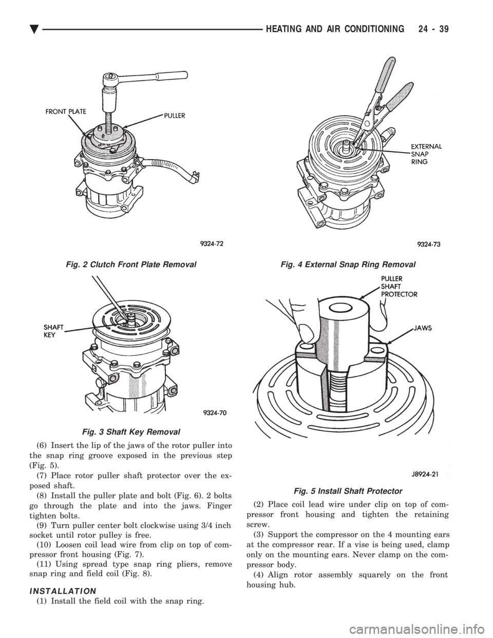
(6) Insert the lip of the jaws of the rotor puller into
the snap ring groove exposed in the previous step
(Fig. 5). (7) Place rotor puller shaft protector over the ex-
posed shaft. (8) Install the puller plate and bolt (Fig. 6). 2 bolts
go through the plate and into the jaws. Finger
tighten bolts. (9) Turn puller center bolt clockwise using 3/4 inch
socket until rotor pulley is free. (10) Loosen coil lead wire from clip on top of com-
pressor front housing (Fig. 7). (11) Using spread type snap ring pliers, remove
snap ring and field coil (Fig. 8).
INSTALLATION
(1) Install the field coil with the snap ring. (2) Place coil lead wire under clip on top of com-
pressor front housing and tighten the retaining
screw. (3) Support the compressor on the 4 mounting ears
at the compressor rear. If a vise is being used, clamp
only on the mounting ears. Never clamp on the com-
pressor body. (4) Align rotor assembly squarely on the front
housing hub.
Fig. 2 Clutch Front Plate Removal
Fig. 3 Shaft Key Removal
Fig. 4 External Snap Ring Removal
Fig. 5 Install Shaft Protector
Ä HEATING AND AIR CONDITIONING 24 - 39
Page 2345 of 2438
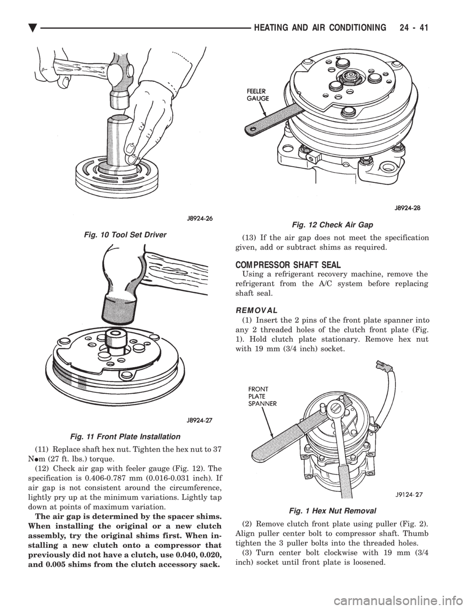
(11) Replace shaft hex nut. Tighten the hex nut to 37
N Im (27 ft. lbs.) torque.
(12) Check air gap with feeler gauge (Fig. 12). The
specification is 0.406-0.787 mm (0.016-0.031 inch). If
air gap is not consistent around the circumference,
lightly pry up at the minimum variations. Lightly tap
down at points of maximum variation. The air gap is determined by the spacer shims.
When installing the original or a new clutch
assembly, try the original shims first. When in-
stalling a new clutch onto a compressor that
previously did not have a clutch, use 0.040, 0.020,
and 0.005 shims from the clutch accessory sack. (13) If the air gap does not meet the specification
given, add or subtract shims as required.
COMPRESSOR SHAFT SEAL
Using a refrigerant recovery machine, remove the
refrigerant from the A/C system before replacing
shaft seal.
REMOVAL
(1) Insert the 2 pins of the front plate spanner into
any 2 threaded holes of the clutch front plate (Fig.
1). Hold clutch plate stationary. Remove hex nut
with 19 mm (3/4 inch) socket.
(2) Remove clutch front plate using puller (Fig. 2).
Align puller center bolt to compressor shaft. Thumb
tighten the 3 puller bolts into the threaded holes. (3) Turn center bolt clockwise with 19 mm (3/4
inch) socket until front plate is loosened.
Fig. 12 Check Air Gap
Fig. 1 Hex Nut Removal
Fig. 10 Tool Set Driver
Fig. 11 Front Plate Installation
Ä HEATING AND AIR CONDITIONING 24 - 41
Page 2349 of 2438
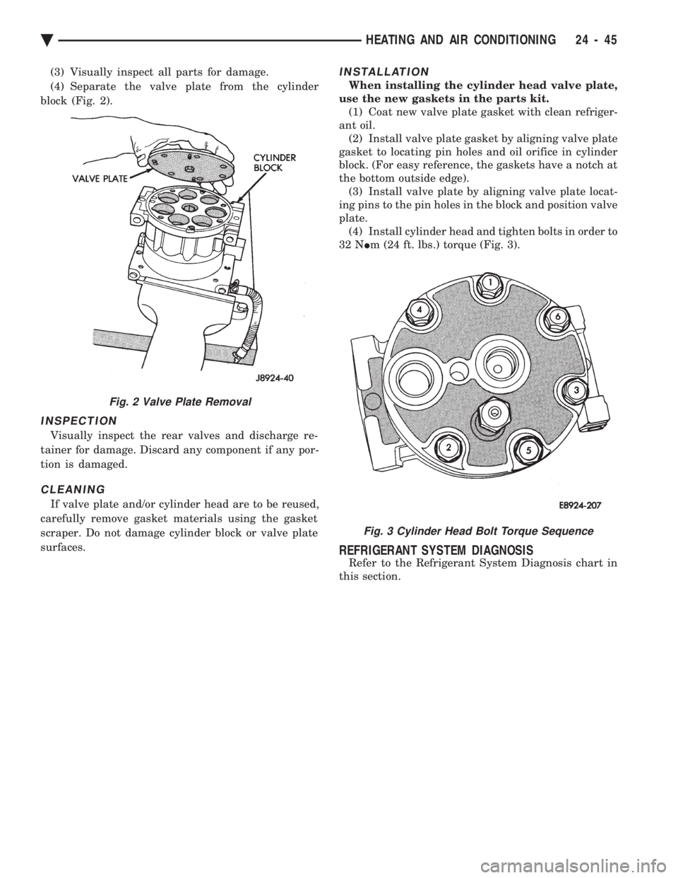
(3) Visually inspect all parts for damage.
(4) Separate the valve plate from the cylinder
block (Fig. 2).
INSPECTION
Visually inspect the rear valves and discharge re-
tainer for damage. Discard any component if any por-
tion is damaged.
CLEANING
If valve plate and/or cylinder head are to be reused,
carefully remove gasket materials using the gasket
scraper. Do not damage cylinder block or valve plate
surfaces.
INSTALLATION
When installing the cylinder head valve plate,
use the new gaskets in the parts kit. (1) Coat new valve plate gasket with clean refriger-
ant oil. (2) Install valve plate gasket by aligning valve plate
gasket to locating pin holes and oil orifice in cylinder
block. (For easy reference, the gaskets have a notch at
the bottom outside edge). (3) Install valve plate by aligning valve plate locat-
ing pins to the pin holes in the block and position valve
plate. (4) Install cylinder head and tighten bolts in order to
32 N Im (24 ft. lbs.) torque (Fig. 3).
REFRIGERANT SYSTEM DIAGNOSIS
Refer to the Refrigerant System Diagnosis chart in
this section.
Fig. 2 Valve Plate Removal
Fig. 3 Cylinder Head Bolt Torque Sequence
Ä HEATING AND AIR CONDITIONING 24 - 45
Page 2351 of 2438
COMPONENT SERVICE PROCEDURES INDEX
page page
Air Distribution Duct ...................... 50
Air Distribution Duct ...................... 52
Ambient Switch .......................... 47
Blend-Air Door .......................... 64
Blower Motor ............................ 58
Blower Motor Wheel Assembly .............. 58
Blower Resistor Block ..................... 49
Condensate Drain Tube ................... 64
Condenser Assembly ...................... 57
Condenser Fan Control Switch .............. 47
Defroster Duct ........................... 51
Defroster Duct Adapter .................... 51
Defroster Ducts/Demister Ducts and Hoses ..... 52
Differential Pressure Cut-Out Switch Diagnosis . . 48
Evaporator Coil .......................... 64 Expansion Valve
......................... 55
Filter-Drier Assembly ...................... 57
Fin-Sensing Cycling Clutch Switch ............ 53
Heater Core ............................ 64
Heater Hoses ........................... 51
Heater-A/C Unit AssemblyÐRemoval and Installation ............................ 61
Heater-A/C Unit Recondition ................ 63
Low or Differential Pressure Cut-Off Switch ..... 54
Temperature Control CableÐAA,AP,AG and AJ Models ............................ 49
Temperature Control CableÐAC/AY Models .... 48
Vacuum ActuatorÐFresh/Recirc Door ......... 50
Vacuum ActuatorsÐMode Doors ............. 52
AMBIENT SWITCH
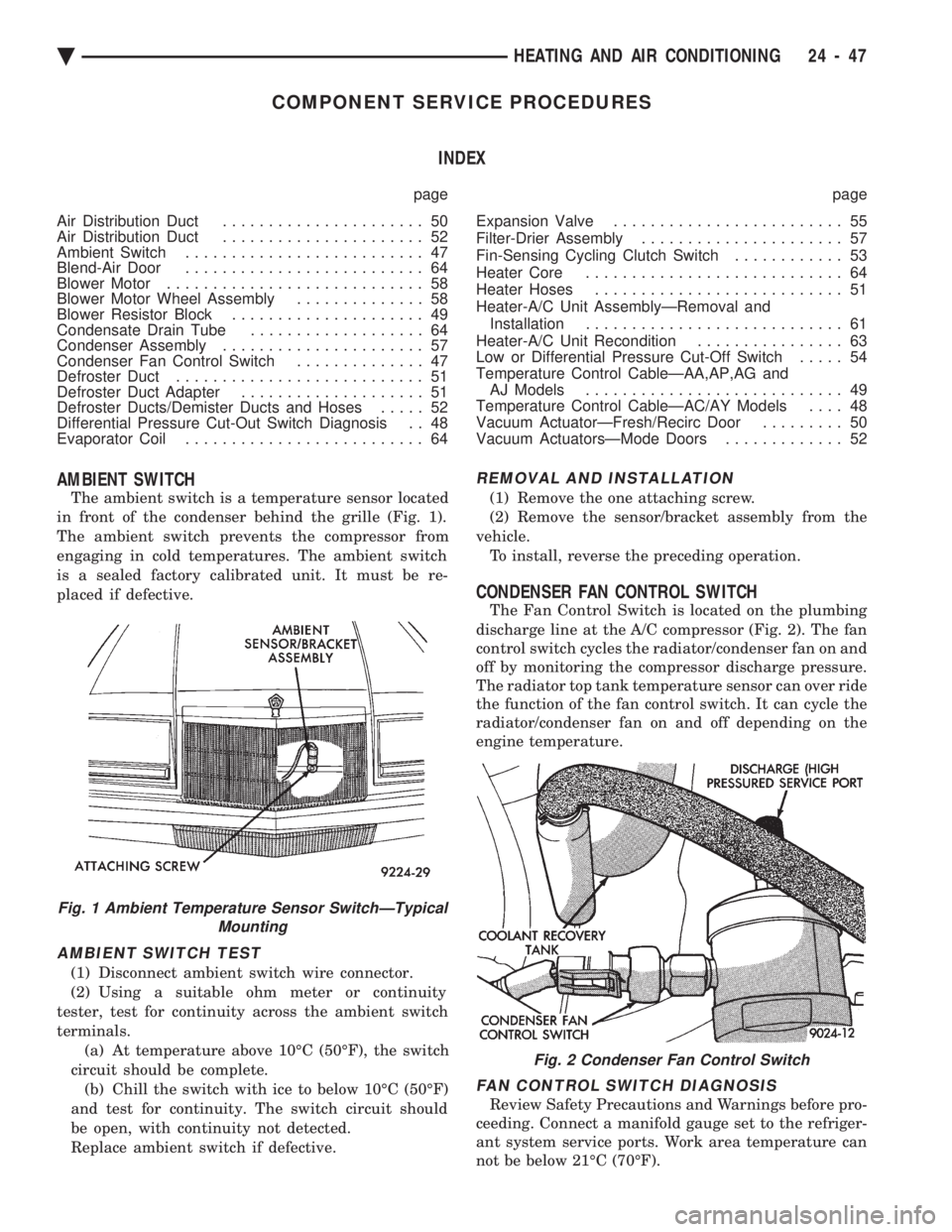
The ambient switch is a temperature sensor located
in front of the condenser behind the grille (Fig. 1).
The ambient switch prevents the compressor from
engaging in cold temperatures. The ambient switch
is a sealed factory calibrated unit. It must be re-
placed if defective.
AMBIENT SWITCH TEST
(1) Disconnect ambient switch wire connector.
(2) Using a suitable ohm meter or continuity
tester, test for continuity across the ambient switch
terminals. (a) At temperature above 10ÉC (50ÉF), the switch
circuit should be complete. (b) Chill the switch with ice to below 10ÉC (50ÉF)
and test for continuity. The switch circuit should
be open, with continuity not detected.
Replace ambient switch if defective.
REMOVAL AND INSTALLATION
(1) Remove the one attaching screw.
(2) Remove the sensor/bracket assembly from the
vehicle. To install, reverse the preceding operation.
CONDENSER FAN CONTROL SWITCH
The Fan Control Switch is located on the plumbing
discharge line at the A/C compressor (Fig. 2). The fan
control switch cycles the radiator/condenser fan on and
off by monitoring the compressor discharge pressure.
The radiator top tank temperature sensor can over ride
the function of the fan control switch. It can cycle the
radiator/condenser fan on and off depending on the
engine temperature.
FAN CONTROL SWITCH DIAGNOSIS
Review Safety Precautions and Warnings before pro-
ceeding. Connect a manifold gauge set to the refriger-
ant system service ports. Work area temperature can
not be below 21ÉC (70ÉF).
Fig. 1 Ambient Temperature Sensor SwitchÐTypical Mounting
Fig. 2 Condenser Fan Control Switch
Ä HEATING AND AIR CONDITIONING 24 - 47
Page 2352 of 2438
WARNING: AVOID RADIATOR/CONDENSER FAN
BLADES WHEN WORKING IN THE RADIATOR
AREA. FAN IS CONTROLLED BY TEMPERATURE
AND CAN START ANY TIME IGNITION IS ON. PER-
SONAL INJURY CAN RESULT.
(1) Disconnect fan control switch wire connector.
(2) Using a suitable jumper wire, jump across ter-
minals in wire connector. (3) Connect a suitable continuity tester across fan
control switch terminals. (4) Start engine and set idle at 1300 rpm. The ra-
diator fan should run constantly. (5) Set the A/C controls to A/C and high blower.
(6) If the high pressure gauge reads below 1102
kPa (160 psi) there should be no continuity across
the switch terminals.
CAUTION: Do not allow engine to overheat when ra-
diator air flow is blocked.
(7) Block radiator air flow with a suitable cover to
increase the high side pressure to at least 1585 kPa
(230 psi). Electrical continuity should be detected
across the fan control switch terminals. (8) Remove cover from front of vehicle to allow
high side pressure to decrease. When pressure drops
below 1102 kPa (160 psi), continuity should cease. If fan control switch is defective, replace it.
REMOVAL AND INSTALLATION
CAUTION: Refrigerant removal is not necessary
when removing the Condenser Fan Control Switch.
However, a small amount of refrigerant will vent
from the switch port. Review the refrigerant han-
dling section of Safety Precautions and Warnings in
the General Information section of this Group.
(1) Disconnect wire connector from condenser fan
control switch. (2) Loosen and quickly rotate the switch counter-
clockwise and separate from the high pressure line
switch port. To install, reverse the preceding operation.
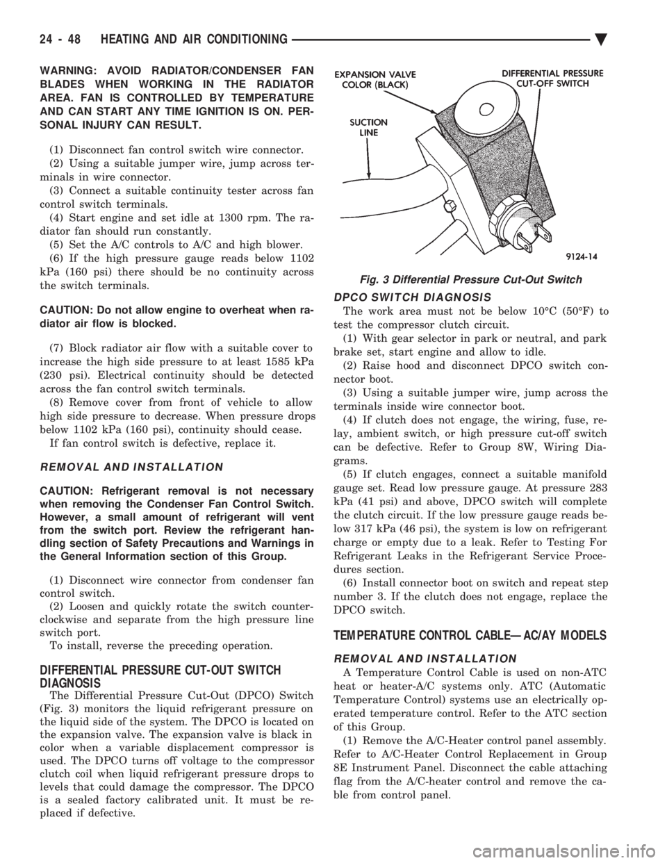
DIFFERENTIAL PRESSURE CUT-OUT SWITCH
DIAGNOSIS
The Differential Pressure Cut-Out (DPCO) Switch
(Fig. 3) monitors the liquid refrigerant pressure on
the liquid side of the system. The DPCO is located on
the expansion valve. The expansion valve is black in
color when a variable displacement compressor is
used. The DPCO turns off voltage to the compressor
clutch coil when liquid refrigerant pressure drops to
levels that could damage the compressor. The DPCO
is a sealed factory calibrated unit. It must be re-
placed if defective.
DPCO SWITCH DIAGNOSIS
The work area must not be below 10ÉC (50ÉF) to
test the compressor clutch circuit. (1) With gear selector in park or neutral, and park
brake set, start engine and allow to idle. (2) Raise hood and disconnect DPCO switch con-
nector boot. (3) Using a suitable jumper wire, jump across the
terminals inside wire connector boot. (4) If clutch does not engage, the wiring, fuse, re-
lay, ambient switch, or high pressure cut-off switch
can be defective. Refer to Group 8W, Wiring Dia-
grams. (5) If clutch engages, connect a suitable manifold
gauge set. Read low pressure gauge. At pressure 283
kPa (41 psi) and above, DPCO switch will complete
the clutch circuit. If the low pressure gauge reads be-
low 317 kPa (46 psi), the system is low on refrigerant
charge or empty due to a leak. Refer to Testing For
Refrigerant Leaks in the Refrigerant Service Proce-
dures section. (6) Install connector boot on switch and repeat step
number 3. If the clutch does not engage, replace the
DPCO switch.
TEMPERATURE CONTROL CABLEÐAC/AY MODELS
REMOVAL AND INSTALLATION
A Temperature Control Cable is used on non-ATC
heat or heater-A/C systems only. ATC (Automatic
Temperature Control) systems use an electrically op-
erated temperature control. Refer to the ATC section
of this Group. (1) Remove the A/C-Heater control panel assembly.
Refer to A/C-Heater Control Replacement in Group
8E Instrument Panel. Disconnect the cable attaching
flag from the A/C-heater control and remove the ca-
ble from control panel.
Fig. 3 Differential Pressure Cut-Out Switch
24 - 48 HEATING AND AIR CONDITIONING Ä
Page 2353 of 2438
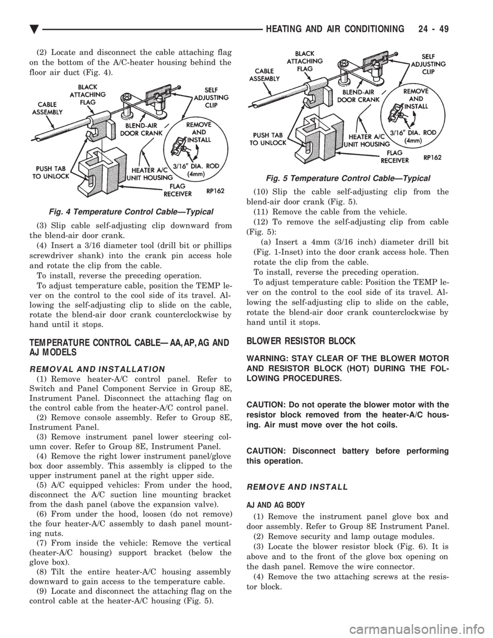
(2) Locate and disconnect the cable attaching flag
on the bottom of the A/C-heater housing behind the
floor air duct (Fig. 4).
(3) Slip cable self-adjusting clip downward from
the blend-air door crank. (4) Insert a 3/16 diameter tool (drill bit or phillips
screwdriver shank) into the crank pin access hole
and rotate the clip from the cable. To install, reverse the preceding operation.
To adjust temperature cable, position the TEMP le-
ver on the control to the cool side of its travel. Al-
lowing the self-adjusting clip to slide on the cable,
rotate the blend-air door crank counterclockwise by
hand until it stops.
TEMPERATURE CONTROL CABLEÐAA,AP,AG AND
AJ MODELS
REMOVAL AND INSTALLATION
(1) Remove heater-A/C control panel. Refer to
Switch and Panel Component Service in Group 8E,
Instrument Panel. Disconnect the attaching flag on
the control cable from the heater-A/C control panel. (2) Remove console assembly. Refer to Group 8E,
Instrument Panel. (3) Remove instrument panel lower steering col-
umn cover. Refer to Group 8E, Instrument Panel. (4) Remove the right lower instrument panel/glove
box door assembly. This assembly is clipped to the
upper instrument panel at the right upper side. (5) A/C equipped vehicles: From under the hood,
disconnect the A/C suction line mounting bracket
from the dash panel (above the expansion valve). (6) From under the hood, loosen (do not remove)
the four heater-A/C assembly to dash panel mount-
ing nuts. (7) From inside the vehicle: Remove the vertical
(heater-A/C housing) support bracket (below the
glove box). (8) Tilt the entire heater-A/C housing assembly
downward to gain access to the temperature cable. (9) Locate and disconnect the attaching flag on the
control cable at the heater-A/C housing (Fig. 5). (10) Slip the cable self-adjusting clip from the
blend-air door crank (Fig. 5). (11) Remove the cable from the vehicle.
(12) To remove the self-adjusting clip from cable
(Fig. 5): (a) Insert a 4mm (3/16 inch) diameter drill bit
(Fig. 1-Inset) into the door crank access hole. Then
rotate the clip from the cable.
To install, reverse the preceding operation.
To adjust temperature cable: Position the TEMP le-
ver on the control to the cool side of its travel. Al-
lowing the self-adjusting clip to slide on the cable,
rotate the blend-air door crank counterclockwise by
hand until it stops.
BLOWER RESISTOR BLOCK
WARNING: STAY CLEAR OF THE BLOWER MOTOR
AND RESISTOR BLOCK (HOT) DURING THE FOL-
LOWING PROCEDURES.
CAUTION: Do not operate the blower motor with the
resistor block removed from the heater-A/C hous-
ing. Air must move over the hot coils.
CAUTION: Disconnect battery before performing
this operation.
REMOVE AND INSTALL
AJ AND AG BODY
(1) Remove the instrument panel glove box and
door assembly. Refer to Group 8E Instrument Panel. (2) Remove security and lamp outage modules.
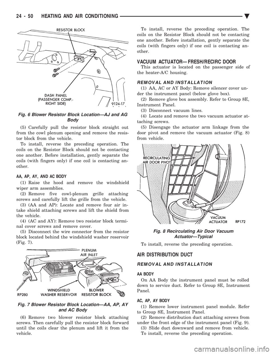
(3) Locate the blower resistor block (Fig. 6). It is
above and to the front of the glove box opening on
the dash panel. Remove the wire connector. (4) Remove the two attaching screws at the resis-
tor block.
Fig. 4 Temperature Control CableÐTypical
Fig. 5 Temperature Control CableÐTypical
Ä HEATING AND AIR CONDITIONING 24 - 49
Page 2354 of 2438
(5) Carefully pull the resistor block straight out
from the cowl plenum opening and remove the resis-
tor block from the vehicle. To install, reverse the preceding operation. The
coils on the Resistor Block should not be contacting
one another. Before installation, gently separate the
coils (with fingers only) if one coil is contacting an-
other.
AA, AP, AY, AND AC BODY
(1) Raise the hood and remove the windshield
wiper arm assemblies. (2) Remove five cowl-plenum grille attaching
screws and carefully lift the grille from the vehicle. (3) (AA and AP): Locate and remove four air in-
take shield attaching screws and lift the shield from
the vehicle. (4) (AC and AY): Remove two resistor block termi-
nal cover screws and remove cover. (5) Disconnect the wire connector from the resistor
block located behind the windshield washer reservoir
(Fig. 7).
(6) Remove two blower resistor block attaching
screws. Then carefully pull the resistor block forward
until the coils clear the plenum and lift it from the
vehicle. To install, reverse the preceding operation. The
coils on the Resistor Block should not be contacting
one another. Before installation, gently separate the
coils (with fingers only) if one coil is contacting an-
other.
VACUUM ACTUATORÐFRESH/RECIRC DOOR
This actuator is located on the passenger side of
the heater-A/C housing.
REMOVAL AND INSTALLATION
(1) AA, AC or AY Body: Remove silencer cover un-
der the instrument panel (below glove box). (2) Remove glove box assembly. Refer to Group 8E,
Instrument Panel. (3) Disconnect vacuum lines.
(4) Locate and remove the two vacuum actuator at-
taching screws. (5) Disengage the actuator arm linkage from the
door pivot and remove the vacuum actuator (Fig. 8)
from vehicle.
To install, reverse the preceding operation.
AIR DISTRIBUTION DUCT
REMOVAL AND INSTALLATION
AA BODY On AA Body the instrument panel must be rolled
down to service duct. Refer to Group 8E, Instrument
Panel.
AC, AP, AY BODY (1) Remove lower instrument panel module. Refer
to Group 8E, Instrument Panel. (2) Remove distribution duct attaching screws from
under the front edge of the instrument panel (Fig. 9). (3) Slide duct downward and remove from vehicle.
To install, reverse the preceding operation.
Fig. 6 Blower Resistor Block LocationÐAJ and AG Body
Fig. 7 Blower Resistor Block LocationÐAA, AP, AYand AC Body
Fig. 8 Recirculating Air Door VacuumActuatorÐTypical
24 - 50 HEATING AND AIR CONDITIONING Ä
Page 2356 of 2438
To install, reverse the preceding operation.
VACUUM ACTUATORSÐMODE DOORS
The Vacuum Actuators for the Mode Doors are lo-
cated on the drivers side of heater/AC housing above
the accelerator pedal.
REMOVAL
(1) Remove the instrument panel cover under the
steering column. Refer to Group 8E, Instrument
Panel. Heat/Defrost Actuator:
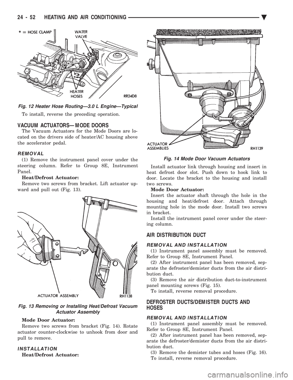
Remove two screws from bracket. Lift actuator up-
ward and pull out (Fig. 13).
Mode Door Actuator:
Remove two screws from bracket (Fig. 14). Rotate
actuator counter-clockwise to unhook from door and
pull to remove.
INSTALLATION
Heat/Defrost Actuator: Install actuator link through housing and insert in
heat defrost door slot. Push down to hook link to
door. Locate the bracket to the housing and install
two screws. Mode Door Actuator:
Insert the actuator shaft through the hole in the
housing and heat/defrost door. Attach through
mounting hole in the mode door. Install two screws
in bracket. Install the instrument panel cover under the steer-
ing column.
AIR DISTRIBUTION DUCT
REMOVAL AND INSTALLATION
(1) Instrument panel assembly must be removed.
Refer to Group 8E, Instrument Panel. (2) After instrument panel has been removed, sep-
arate the defroster/demister ducts from the air distri-
bution duct. (3) Remove the air distribution duct-to-instrument
panel mounting screws (Fig. 15). To install, reverse removal procedure.
DEFROSTER DUCTS/DEMISTER DUCTS AND
HOSES
REMOVAL AND INSTALLATION
(1) Instrument panel assembly must be removed.
Refer to Group 8E, Instrument Panel. (2) After instrument panel has been removed, sep-
arate the defroster/demister ducts from the air distri-
bution duct. (3) Remove the demister tubes and hoses (Fig. 16).
To install, reverse removal procedure.
Fig. 12 Heater Hose RoutingÐ3.0 L EngineÐTypical
Fig. 13 Removing or Installing Heat/Defrost Vacuum Actuator Assembly
Fig. 14 Mode Door Vacuum Actuators
24 - 52 HEATING AND AIR CONDITIONING Ä
Page 2362 of 2438
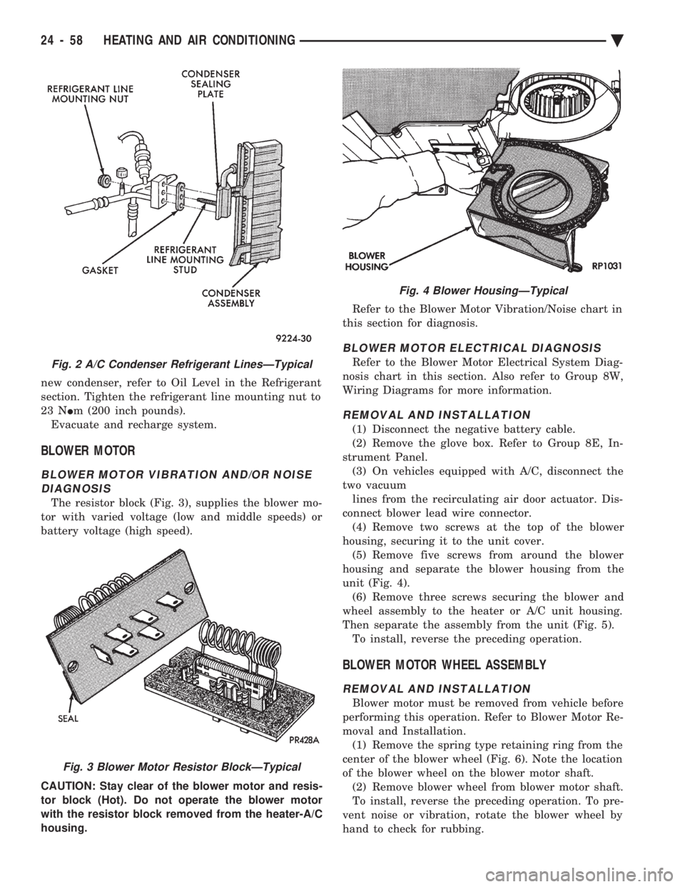
new condenser, refer to Oil Level in the Refrigerant
section. Tighten the refrigerant line mounting nut to
23 N Im (200 inch pounds).
Evacuate and recharge system.
BLOWER MOTOR
BLOWER MOTOR VIBRATION AND/OR NOISE DIAGNOSIS
The resistor block (Fig. 3), supplies the blower mo-
tor with varied voltage (low and middle speeds) or
battery voltage (high speed).
CAUTION: Stay clear of the blower motor and resis-
tor block (Hot). Do not operate the blower motor
with the resistor block removed from the heater-A/C
housing. Refer to the Blower Motor Vibration/Noise chart in
this section for diagnosis.
BLOWER MOTOR ELECTRICAL DIAGNOSIS
Refer to the Blower Motor Electrical System Diag-
nosis chart in this section. Also refer to Group 8W,
Wiring Diagrams for more information.
REMOVAL AND INSTALLATION
(1) Disconnect the negative battery cable.
(2) Remove the glove box. Refer to Group 8E, In-
strument Panel. (3) On vehicles equipped with A/C, disconnect the
two vacuum lines from the recirculating air door actuator. Dis-
connect blower lead wire connector. (4) Remove two screws at the top of the blower
housing, securing it to the unit cover. (5) Remove five screws from around the blower
housing and separate the blower housing from the
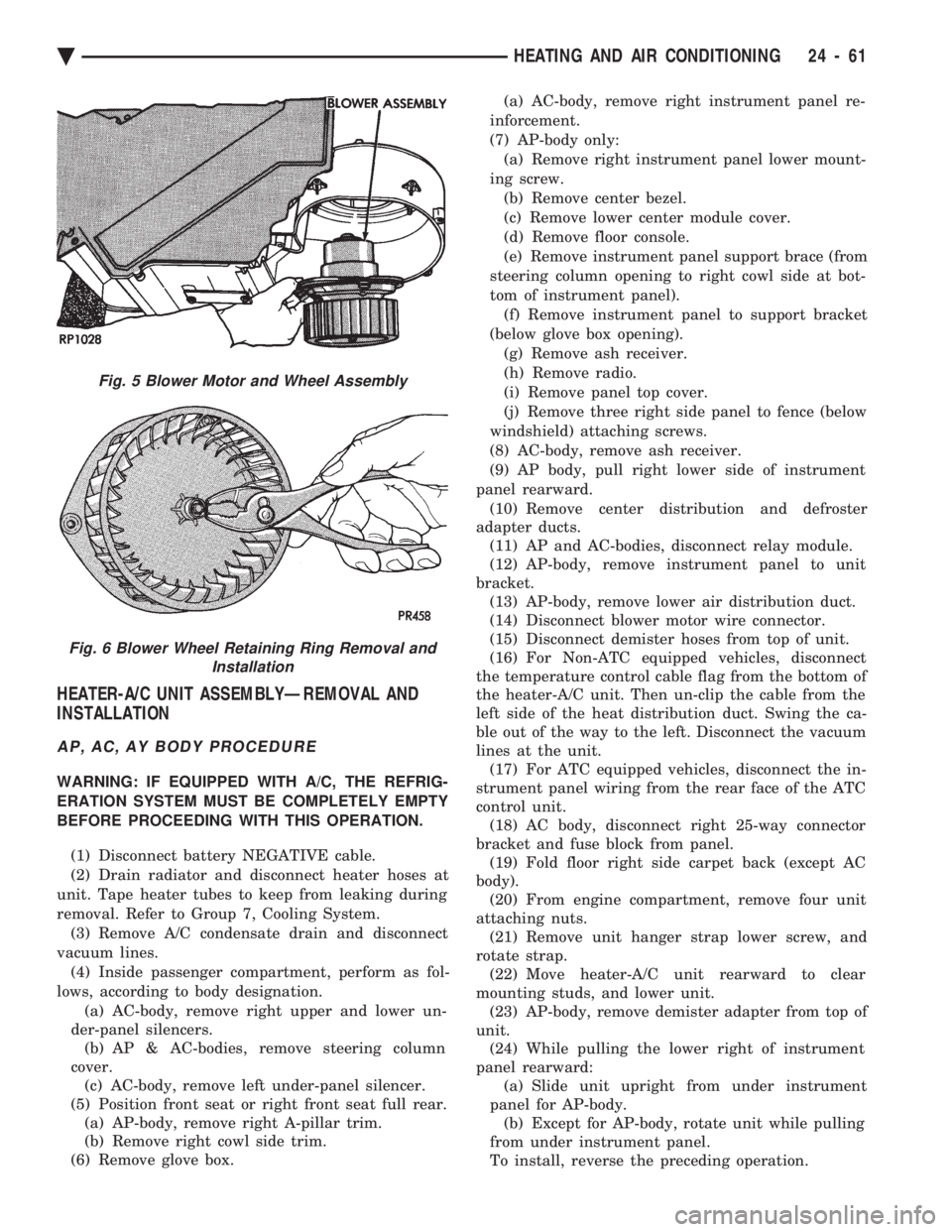
unit (Fig. 4). (6) Remove three screws securing the blower and
wheel assembly to the heater or A/C unit housing.
Then separate the assembly from the unit (Fig. 5). To install, reverse the preceding operation.
BLOWER MOTOR WHEEL ASSEMBLY
REMOVAL AND INSTALLATION
Blower motor must be removed from vehicle before
performing this operation. Refer to Blower Motor Re-
moval and Installation. (1) Remove the spring type retaining ring from the
center of the blower wheel (Fig. 6). Note the location
of the blower wheel on the blower motor shaft. (2) Remove blower wheel from blower motor shaft.
To install, reverse the preceding operation. To pre-
vent noise or vibration, rotate the blower wheel by
hand to check for rubbing.
Fig. 2 A/C Condenser Refrigerant LinesÐTypical
Fig. 3 Blower Motor Resistor BlockÐTypical
Fig. 4 Blower HousingÐTypical
24 - 58 HEATING AND AIR CONDITIONING Ä
Page 2365 of 2438
HEATER-A/C UNIT ASSEMBLYÐREMOVAL AND
INSTALLATION
AP, AC, AY BODY PROCEDURE
WARNING: IF EQUIPPED WITH A/C, THE REFRIG-
ERATION SYSTEM MUST BE COMPLETELY EMPTY
BEFORE PROCEEDING WITH THIS OPERATION.
(1) Disconnect battery NEGATIVE cable.
(2) Drain radiator and disconnect heater hoses at
unit. Tape heater tubes to keep from leaking during
removal. Refer to Group 7, Cooling System. (3) Remove A/C condensate drain and disconnect
vacuum lines. (4) Inside passenger compartment, perform as fol-
lows, according to body designation. (a) AC-body, remove right upper and lower un-
der-panel silencers. (b) AP & AC-bodies, remove steering column
cover. (c) AC-body, remove left under-panel silencer.
(5) Position front seat or right front seat full rear. (a) AP-body, remove right A-pillar trim.
(b) Remove right cowl side trim.
(6) Remove glove box. (a) AC-body, remove right instrument panel re-
inforcement.
(7) AP-body only: (a) Remove right instrument panel lower mount-
ing screw. (b) Remove center bezel.
(c) Remove lower center module cover.
(d) Remove floor console.
(e) Remove instrument panel support brace (from
steering column opening to right cowl side at bot-
tom of instrument panel). (f) Remove instrument panel to support bracket
(below glove box opening). (g) Remove ash receiver.
(h) Remove radio.
(i) Remove panel top cover.
(j) Remove three right side panel to fence (below
windshield) attaching screws.
(8) AC-body, remove ash receiver.
(9) AP body, pull right lower side of instrument
panel rearward. (10) Remove center distribution and defroster
adapter ducts. (11) AP and AC-bodies, disconnect relay module.
(12) AP-body, remove instrument panel to unit
bracket. (13) AP-body, remove lower air distribution duct.
(14) Disconnect blower motor wire connector.
(15) Disconnect demister hoses from top of unit.
(16) For Non-ATC equipped vehicles, disconnect
the temperature control cable flag from the bottom of
the heater-A/C unit. Then un-clip the cable from the
left side of the heat distribution duct. Swing the ca-
ble out of the way to the left. Disconnect the vacuum
lines at the unit. (17) For ATC equipped vehicles, disconnect the in-
strument panel wiring from the rear face of the ATC
control unit. (18) AC body, disconnect right 25-way connector
bracket and fuse block from panel. (19) Fold floor right side carpet back (except AC
body). (20) From engine compartment, remove four unit
attaching nuts. (21) Remove unit hanger strap lower screw, and
rotate strap. (22) Move heater-A/C unit rearward to clear
mounting studs, and lower unit. (23) AP-body, remove demister adapter from top of
unit. (24) While pulling the lower right of instrument
panel rearward: (a) Slide unit upright from under instrument
panel for AP-body. (b) Except for AP-body, rotate unit while pulling
from under instrument panel.
To install, reverse the preceding operation.
Fig. 5 Blower Motor and Wheel Assembly
Fig. 6 Blower Wheel Retaining Ring Removal and Installation
Ä HEATING AND AIR CONDITIONING 24 - 61