sensor CHRYSLER ASPEN 2008 2.G Owners Manual
[x] Cancel search | Manufacturer: CHRYSLER, Model Year: 2008, Model line: ASPEN, Model: CHRYSLER ASPEN 2008 2.GPages: 479, PDF Size: 4.3 MB
Page 40 of 479
WARNING!
During power operation, personal injury or cargo
damage may occur. Ensure the liftgate travel path is
clear. Make sure the liftgate is closed and latched
before driving away.
A beeping signal will sound two seconds before the
liftgate starts to open or close.
NOTE:
²If anything obstructs the power liftgate while it is
closing or opening, the liftgate will automatically
reverse to the closed or open position, provided it
meets sufficient resistance.
²There are also pinch sensors attached to the side of the
liftgate. Light pressure anywhere along these strips
will cause the liftgate to return to the open position.
²The power liftgate must be in the full open position in
order to power close. If the liftgate is not fully open,
press the RKE Transmitter or overhead console button
to fully open the liftgate and then press again to close.
²If the liftgate handle is pulled while the power liftgate
is closing, the liftgate will reverse to the full open
position.
²If the liftgate handle is pulled while the power liftgate
is opening, the liftgate motor will disengage to allow
manual operation.
²The power liftgate buttons will not operate if the
vehicle is in gear or the vehicle speed is above 0 mph
(0 km/h).
THINGS TO KNOW BEFORE STARTING YOUR VEHICLE 39
2
Page 58 of 479
Airbag System Components
The airbag system consists of the following:
²Occupant Restraint Controller
²Side Remote Acceleration Sensors
²Airbag Warning Light
²Driver Airbag
²Passenger Airbag
²Window Bags above Side Windows
²Steering Wheel and Column
²Instrument Panel
²Interconnecting Wiring
²Knee Impact Bolsters
²Front Acceleration Sensors
²Driver and Front Passenger Seat Belt Pretensioners
How the Airbag System Works
²
TheOccupant Restraint Controller (ORC)determines
if a frontal collision is severe enough to require the
airbags to inflate. The front airbag inflators are de-
signed to provide different rates of airbag inflation
from direction provided by the ORC. The ORC will
detect a roll over when equipped with side airbags.
The ORC also monitors the readiness of the electronic
parts of the system whenever the ignition switch is in
the START or RUN positions. These include all of the
items listed above except the steering wheel and
column, and knee bolsters. If the key is in the OFF
position, in the ACC position, or not in the ignition,
the airbags are not ªonº and will not inflate.
During a moderate-to-severe rear impact the ORC may
deploy the seat belt pretensioners alone.
THINGS TO KNOW BEFORE STARTING YOUR VEHICLE 57
2
Page 60 of 479
²TheSide Impact SRS Window Bagsare designed to
activate only in certain side collisions or in a roll over
event. When the ORC (with side impact option) de-
tects a collision or roll over requiring the window bags
to inflate, it signals the inflators on the crash side of the
vehicle. Both window bags will inflate in a roll over
event. A quantity of nontoxic gas is generated to inflate
the window bag. The inflating window bag pushes the
outside edge of the headliner out of the way and
covers the window. The airbag inflates in about 30
milliseconds (about one quarter of the time it takes to
blink your eyes) with enough force to injure you if you
are not belted and seated properly, or if items are
positioned in the area where the window bag inflates.
This especially applies to children. The window bag is
only about 3-1/2 in (9 cm) thick when it is inflated.NOTE:At no time should any Supplemental Restraint
System (SRS) component or SRS-related component or
fastener be modified or replaced with any part except
those which are approved by DaimlerChrysler/Mopart.
²TheKnee Impact Bolstershelp protect the knees of
the driver and the front passenger, and position every-
one for the best interaction with the front airbag.
If A Deployment Occurs
The airbag system is designed to deploy the airbags
when the impact sensors detect a moderate-to-severe
frontal collision, to help restrain the driver and front
passenger, and then immediately deflate.
NOTE:A frontal collision that is not severe enough to
need airbag protection will not activate the system. This
does not mean something is wrong with the airbag
system.
THINGS TO KNOW BEFORE STARTING YOUR VEHICLE 59
2
Page 148 of 479
Automatic Headlights Ð If Equipped
Automatic headlights can be activated by rotating the
rotary headlight switch to the symbol ªA.º The head-
lights will turn on when the engine is running and the
ambient light sensor indicates that the headlights should
be activated. The headlights will turn off if the headlight
switch is rotated to the OFF position or 90 seconds after
the ignition is turned to OFF.
Headlights, Parking Lights, Panel Lights
When the headlight switch is rotated to the first position
to the right, the parking lights, taillights, side marker
lights, license plate light and instrument panel lights are
all turned on. The headlights will turn ON when the
switch is rotated to the second position.
Your vehicle is equipped with plastic headlight lenses
that are lighter and less susceptible to stone breakage
than glass headlights.Plastic is not as scratch resistant as glass and therefore
different lens cleaning procedures must be followed.
To minimize the possibility of scratching the lenses and
reducing light output, avoid wiping with a dry cloth. To
remove road dirt, wash with a mild soap solution fol-
lowed by rinsing.
Do not use abrasive cleaning components, solvents, steel
wool or other abrasive materials to clean the lenses.Illuminated Entry
Headlights turn on for 90 seconds, when the Remote
Keyless Entry UNLOCK button is pressed.
The illuminated entry time is programmable on vehicles
equipped with the Electronic Vehicle Information Center
(EVIC). For details, refer to ªPersonal Settings (Customer
Programmable Features)º under ªOverhead Console
with Electronic Vehicle Information Center (EVIC) ± If
Equippedº in Section 3.
UNDERSTANDING THE FEATURES OF YOUR VEHICLE 147
3
Page 161 of 479
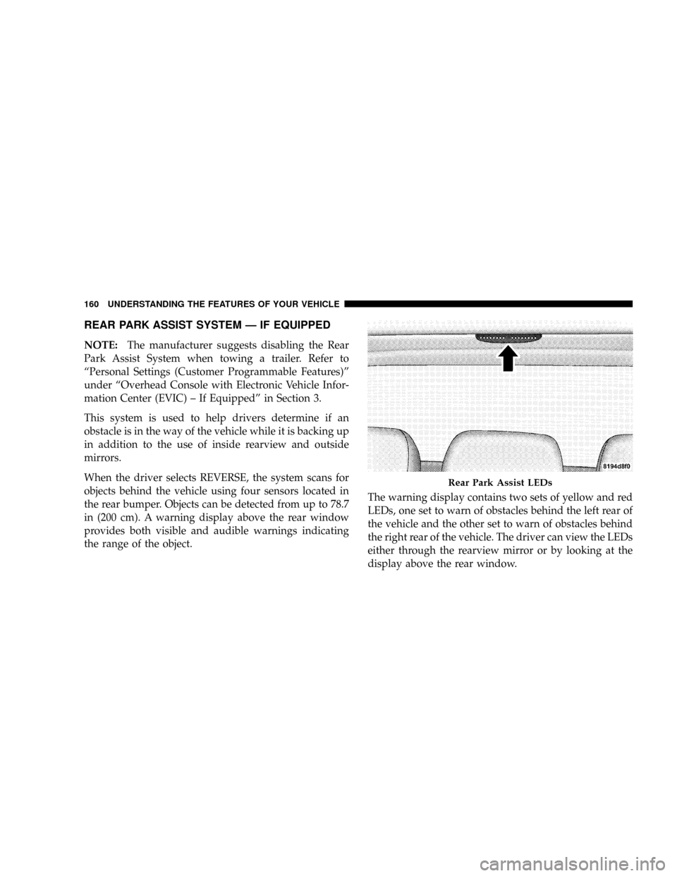
REAR PARK ASSIST SYSTEM Ð IF EQUIPPED
NOTE:The manufacturer suggests disabling the Rear
Park Assist System when towing a trailer. Refer to
ªPersonal Settings (Customer Programmable Features)º
under ªOverhead Console with Electronic Vehicle Infor-
mation Center (EVIC) ± If Equippedº in Section 3.
This system is used to help drivers determine if an
obstacle is in the way of the vehicle while it is backing up
in addition to the use of inside rearview and outside
mirrors.
When the driver selects REVERSE, the system scans for
objects behind the vehicle using four sensors located in
the rear bumper. Objects can be detected from up to 78.7
in (200 cm). A warning display above the rear window
provides both visible and audible warnings indicating
the range of the object.The warning display contains two sets of yellow and red
LEDs, one set to warn of obstacles behind the left rear of
the vehicle and the other set to warn of obstacles behind
the right rear of the vehicle. The driver can view the LEDs
either through the rearview mirror or by looking at the
display above the rear window.
Rear Park Assist LEDs
160 UNDERSTANDING THE FEATURES OF YOUR VEHICLE
Page 163 of 479
WARNING!
²Drivers must be careful when backing up, even when
using the Rear Park Assist System. Always check
carefully behind your vehicle, look behind you, and
be sure to check for pedestrians, animals, other ve-
hicles, obstructions, and blind spots before backing
up. You are responsible for safety and must continue
to pay attention to your surroundings. Failure to do so
can result in serious injury or death.
²Before using the Rear Park Assist System, it is
strongly recommended that the ball mount and hitch
ball assembly is disconnected from the vehicle when
the vehicle is not used for towing. Failure to do so can
result in injury or damage to vehicles or obstacles
because the hitch ball will be much closer to the
obstacle than the rear fascia when the warning dis-
play turns the red LEDs ON. Also, the sensors could
detect the ball mount and hitch ball assembly, de-
pending on its size and shape, giving a false indica-
tion that an obstacle is behind the vehicle.
CAUTION!
²The Rear Park Assist System is only a parking aid
and it is unable to recognize every obstacle, in-
cluding small obstacles. Parking curbs might be
temporarily detected or not detected at all. Ob-
stacles located above or below the sensors will not
be detected when they are in close proximity.
²The vehicle must be driven slowly when using the
Rear Park Assist System to be able to stop in time
when the obstacle is detected. It is recommended
that the driver look over his/her shoulder when
using the Rear Park Assist System.
162 UNDERSTANDING THE FEATURES OF YOUR VEHICLE
Page 175 of 479

Manual Compass Calibration
If the compass appears erratic and the ªCALº message
does not appear in the EVIC display, you must put the
compass into the Calibration Mode manually as follows:
1.Turn the ignition switch to the ON/RUN position.
2.Press the MENU buttonuntil ªPersonal
Settingsº is displayed.
3.Press the STEP buttonuntil ªCalibrate Compass YESº
is displayed.
4.Press and release the RESET buttonto start the
calibration. The message ªCALº will display on the
compass temperature screen in the EVIC.5.Slowly drive the vehicle at a speed of 5 mph (8 km/h)
in a complete 360Écircle, (in an area free from large
metal or metallic objects) until the ªCALº message
turns off. The compass will now function normally.
Compass Variance
Compass variance is the difference between magnetic
North and geographic North. In some areas of the
country, the difference between magnetic and geographic
North is great enough to cause the compass to give false
readings. If this occurs, the compass variance must be set
using the following procedure:
NOTE:Magnetic materials should be kept away from
the overhead console. This is where the compass sensor is
located.
174 UNDERSTANDING THE FEATURES OF YOUR VEHICLE
Page 214 of 479
tires or wheels on your vehicle to ensure that the replace-
ment or alternate tires and wheels allow the TPMS to
continue to function properly.
CAUTION!
The TPMS has been optimized for the original
equipment tires and wheels. TPMS pressures and
warning have been established for the tire size
equipped on your vehicle. Undesirable system opera-
tion or sensor damage may result when using re-
placement equipment that is not of the same size,
type, and/or style. Aftermarket wheels can cause
sensor damage. Do not use tire sealant from a can, or
balance beads if your vehicle is equipped with a
TPMS, as damage to the sensors may result.25. Airbag Indicator
The indicator lights and remains lit for six to
eight seconds when the ignition is first turned
ON. If the light does not come on when the
ignition is first turned on, or the light stays on
or comes on while driving, have the airbag system
checked by an authorized dealer.
26. 4WD Indicator
Indicates when the transfer case is in 4WD position.
27. SVC (Service) 4WD Indicator
The SVC 4WD lights will come on when the ignition key
is turned to the ON position and will stay on for two
seconds. If the light stays on or comes on during driving,
it means that the 4WD system is not functioning properly
and that service is required. See your authorized dealer
for service.
INSTRUMENT PANEL AND CONTROLS 213
4
Page 256 of 479
displayed. The ATC system uses an infrared sensor
located in the overhead console to measure the tem-
perature of the driver and passengers. Based on the
sensor input, the system will automatically control
comfort by varying the temperature, fan speed, and
mode. This maintains a comfortable temperature, even
under changing conditions. It is important that objects
are not blocking the infrared sensor. It is also impor-
tant that objects are not used that may scratch or
damage it in any way.
Level Of Automatic Control
72ÉF (22ÉC) is the recommended setting for maximum
comfort for the average person, however, this may vary.
NOTE:The temperature setting can be adjusted at any
time without affecting automatic control operation. It is
not necessary to move the temperature setting for cold orhot vehicles. The system automatically adjusts the tem-
perature, mode and fan speed to provide comfort as
quickly as possible.
NOTE:In cold weather, the fan will not turn on in Auto
mode until the engine coolant has warmed up suffi-
ciently. This is indicated by the ªWARM UP DELAYº
message on the display.
NOTE:The temperature can be displayed in U.S. or
Metric by selecting the U.S./METRIC Customer-
Programmable feature. Refer to9Overhead Console
Customer-Programmable Features9in Section 3. The
mode will also be shown in the display and will change
as required during automatic operation.
NOTE:The system can be put into recirculate mode
without affecting ATC operation. This will prevent out-
side air from entering the vehicle. Use this mode to
temporarily block out any outside odors, smoke, or dust.
INSTRUMENT PANEL AND CONTROLS 255
4
Page 299 of 479

WARNING!
Many factors, such as vehicle loading, road condi-
tions and driving conditions, influence the chance
that wheel lift or rollover may occur.
²ERM cannot prevent all wheel lift or rollovers,
especially those that involve leaving the roadway
or striking objects or other vehicles. Only a safe,
attentive, and skillful driver can prevent accidents.
²The capabilities of an ERM-equipped vehicle
must never be exploited in a reckless or dangerous
manner which could jeopardize the user's safety
or the safety of others.
Electronic Stability Program (ESP)
This system enhances directional control and stability of
the vehicle under various driving conditions. ESP cor-
rects for over/under steering of the vehicle by applying
the brake of the appropriate wheel to assist in counter-
acting the over/under steer condition. Engine power
may also be reduced to help the vehicle maintain the
desired path.
ESP uses sensors in the vehicle to determine the vehicle
path intended by the driver and compares it to the actual
path of the vehicle. When the actual path does not match
the intended path, ESP applies the brake of the appropri-
ate wheel to assist in counteracting the oversteer or
understeer condition.
²Oversteer - when the vehicle is turning more than
appropriate for the steering wheel position.
298 STARTING AND OPERATING