key CHRYSLER CARAVAN 2002 Owner's Manual
[x] Cancel search | Manufacturer: CHRYSLER, Model Year: 2002, Model line: CARAVAN, Model: CHRYSLER CARAVAN 2002Pages: 2399, PDF Size: 57.96 MB
Page 363 of 2399
(2) Turn the ignition switch on and access the
ªRead Faultº screen.
(3) Record all the DTC's and ªfreeze frameº infor-
mation shown on the DRB scan tool.
(4) To erase DTC's, use the ªErase Trouble Codeº
data screen on the DRB scan tool.Do not erase any
DTC's until problems have been investigated
and repairs have been performed.
OBTAINING DTC'S USING IGNITION KEY
(1) Cycle the ignition key On - Off - On - Off - On
within 5 seconds.
(2) The Odometer will show the P-code for the
DTC code number. Refer to the Emission section for
the DTC chart for a detailed explanation of the DTC
codes.
(3) If no DTC's are present, the cluster will display
one of two texts: ªP1684º and ªdoneº or only ªdoneº.
²P1684 is only a status and indicates that the
PCM memory has been cleared within the last 50
ignition cycles and does not indicate a problem.
²done indicates that NO DTCs are present and
the procedure is complete.
REMOVAL
(1) Disconnect the negative battery cable.
(2) Remove the battery shield, refer to the Battery
section for more information.
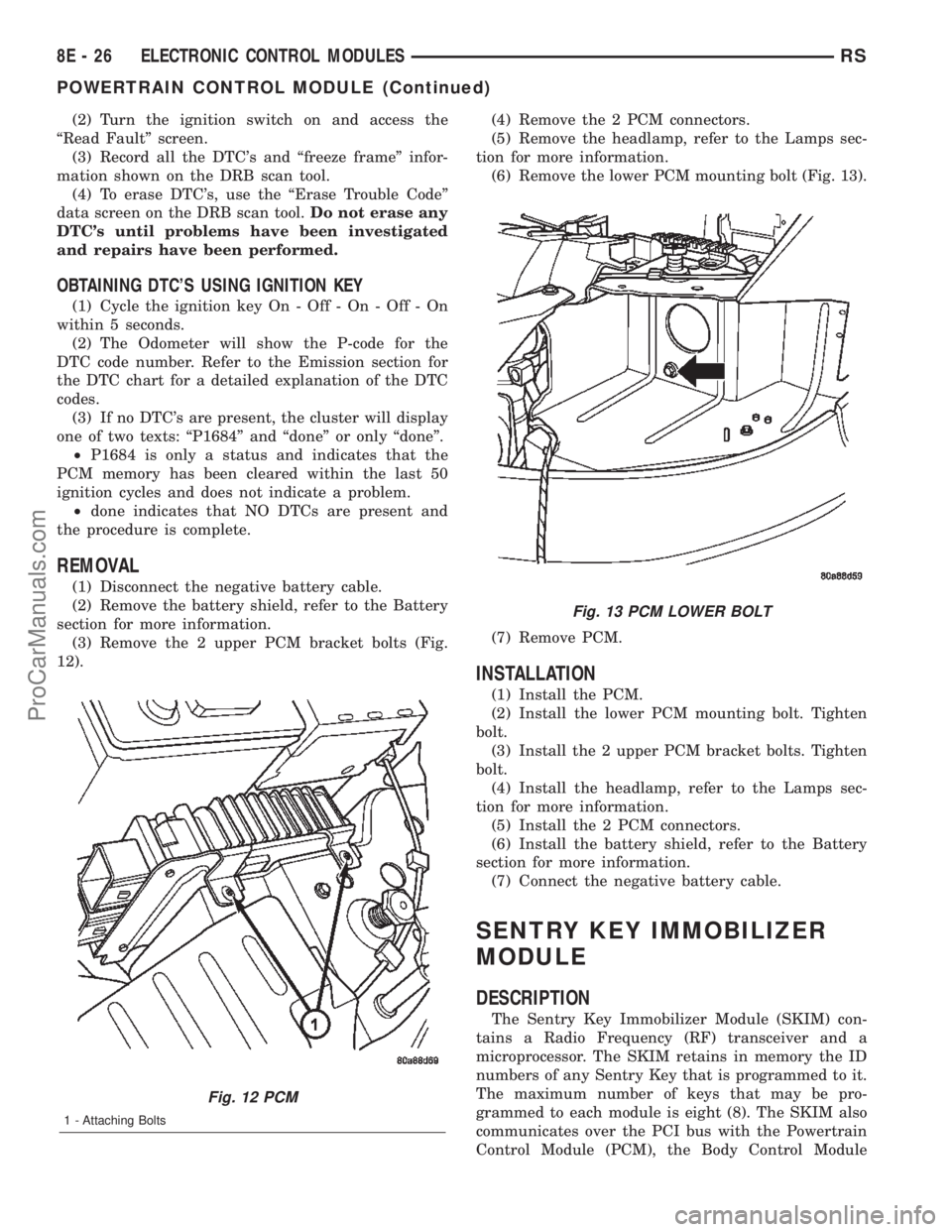
(3) Remove the 2 upper PCM bracket bolts (Fig.
12).(4) Remove the 2 PCM connectors.
(5) Remove the headlamp, refer to the Lamps sec-
tion for more information.
(6) Remove the lower PCM mounting bolt (Fig. 13).
(7) Remove PCM.
INSTALLATION
(1) Install the PCM.
(2) Install the lower PCM mounting bolt. Tighten
bolt.
(3) Install the 2 upper PCM bracket bolts. Tighten
bolt.
(4) Install the headlamp, refer to the Lamps sec-
tion for more information.
(5) Install the 2 PCM connectors.
(6) Install the battery shield, refer to the Battery
section for more information.
(7) Connect the negative battery cable.
SENTRY KEY IMMOBILIZER
MODULE
DESCRIPTION
The Sentry Key Immobilizer Module (SKIM) con-
tains a Radio Frequency (RF) transceiver and a
microprocessor. The SKIM retains in memory the ID
numbers of any Sentry Key that is programmed to it.
The maximum number of keys that may be pro-
grammed to each module is eight (8). The SKIM also
communicates over the PCI bus with the Powertrain
Control Module (PCM), the Body Control Module
Fig. 12 PCM
1 - Attaching Bolts
Fig. 13 PCM LOWER BOLT
8E - 26 ELECTRONIC CONTROL MODULESRS
POWERTRAIN CONTROL MODULE (Continued)
ProCarManuals.com
Page 364 of 2399

(BCM), and the DRB IIItscan tool. The SKIM trans-
mits and receives RF signals through a tuned
antenna enclosed within a molded plastic ring forma-
tion that is integral to the SKIM housing. When the
SKIM is properly installed on the steering column,
the antenna ring fits snugly around the circumfer-
ence of the ignition lock cylinder housing. If this ring
is not mounted properly, communication problems
may arise in the form of transponder-related faults.
For added system security, each SKIM is pro-
grammed with a unique9Secret Key9code. This code
is stored in memory and is sent over the PCI bus to
the PCM and to each key that is programmed to
work with the vehicle. The9Secret Key9code is there-
fore a common element found in all components of
the Sentry Key Immobilizer System (SKIS). In the
event that a SKIM replacement is required, the
9Secret Key9code can be restored from the PCM by
following the SKIM replacement procedure found in
the DRB IIItscan tool. Proper completion of this
task will allow the existing ignition keys to be repro-
grammed. Therefore, new keys will NOT be needed.
In the event that the original9Secret Key9code can
not be recovered, new ignition keys will be required.
The DRB IIItscan tool will alert the technician if
key replacement is necessary. Another security code,
called a PIN, is used to gain secured access to the
SKIM for service. The SKIM also stores in its mem-
ory the Vehicle Identification Number (VIN), which it
learns through a bus message from the assembly
plant tester. The SKIS scrambles the information
that is communicated between its components in
order to reduce the possibility of unauthorized SKIM
access and/or disabling.
OPERATION
When the ignition switch is moved to the RUN
position, the SKIM transmits an RF signal to the
transponder in the ignition key. The SKIM then
waits for a response RF signal from the transponder
in the key. If the response received identifies the key
as valid, the SKIM sends a9valid key9message to
the PCM over the PCI bus. If the response received
identifies the key as invalid or no response is
received from the transponder in the ignition key, the
SKIM sends an9invalid key9message to the PCM.
The PCM will enable or disable engine operation
based upon the status of the SKIM messages. It is
important to note that the default condition in the
PCM is9invalid key.9Therefore, if no response is
received by the PCM, the engine will be immobilized
after two (2) seconds of running.The SKIM also sends indicator light status mes-
sages to the BCM to operate the light. This is the
method used to turn the light ON solid or to flash it
after the indicator light test is complete to signify a
fault in the SKIS. If the light comes ON and stays
ON solid after the indicator light test, this signifies
that the SKIM has detected a system malfunction
and/or that the SKIS has become inoperative. If the
SKIM detects an invalid keyORa key-related fault
exists, the indicator light will flash following the
indicator light test. The SKIM may also request an
audible chime if the customer key programming fea-
ture is available and the procedure is being utilized
(Refer to 8 - ELECTRICAL/VEHICLE THEFT SECU-
RITY/TRANSPONDER KEY - STANDARD PROCE-
DURE).
REMOVAL
(1)Disconnect and isolate the battery negative cable.
(2) Remove Lower Instrument Panel Cover. Refer
to Body, Instrument Panel, Lower Instrument Panel
Cover, Removal.
(3) Remove the steering column upper and lower
shrouds. Refer to Steering, Column, Column Shroud,
Removal.
(4) Disengage the steering column wire harness
from the Sentry Key Immobilizer Module (SKIM).
(5) Remove the one screws securing the SKIM to
the steering column.
(6) Rotate the SKIM upwards and then to the side
away from the steering column to slide the SKIM
antenna ring from around the ignition switch lock
cylinder housing.
(7) Remove the SKIM from the vehicle.
INSTALLATION
(1) Slip the SKIM antenna ring around the igni-
tion switch lock cylinder housing. Rotate the SKIM
downwards and then towards the steering column.
(2) Install the one screws securing the SKIM to
the steering column.
(3) Engage the steering column wire harness from
the Sentry Key Immobilizer Module (SKIM).
(4) Install the steering column upper and lower
shrouds. Refer to Steering, Column, Column Shroud,
Installation.
(5) Install the Lower Instrument Panel Cover.
Refer to Body, Instrument Panel, Lower Instrument
Panel Cover, Installation.
(6) Connect the battery negative cable.
RSELECTRONIC CONTROL MODULES8E-27
SENTRY KEY IMMOBILIZER MODULE (Continued)
ProCarManuals.com
Page 373 of 2399
these sensor inputs to adjust fuel quantity and fuel
injector timing.
Limp-In Mode
If there is a fault detected with the accelerator
pedal position sensor, the ECM will set the engine
speed at 1100 RPM.
Overspeed Detection Mode
If the ECM detects engine RPM that exceeds 5200
RPM, the ECM will set a DTC in memory and illu-
minate the MIL until the DTC is cleared.
After-Run Mode
The ECM transfers RAM information to ROM and
performs an Input/Output state check.
MONITORED CIRCUITS
The ECM is able to monitor and identify most
driveability related trouble conditions. Some circuits
are directly monitored through ECM feedback cir-
cuitry. In addition, the ECM monitors the voltage
state of some circuits and compares those states with
expected values. Other systems are monitored indi-
rectly when the ECM conducts a rationality test to
identify problems. Although most subsytems of the
engine control module are either directly or indirectly
monitored, there may be occasions when diagnostic
trouble codes are not immediately identified. For a
trouble code to set, a specific set of conditions must
occur and unless these conditions occur, a DTC will
not set.
DIAGNOSTIC TROUBLE CODES
Each diagnostic trouble code (DTC) is diagnosed by
following a specific procedure. The diagnostic test
procedure contains step-by-step instruction for deter-
mining the cause of the DTC as well as no trouble
code problems. Refer to the appropriate Diesel Pow-
ertrain Diagnostic Manual for more information.
HARD CODE
A DTC that comes back within one cycle of the
ignition key is a hard code. This means that the
problem is current every time the ECM/SKIM checks
that circuit or function. Procedures in this manual
verify if the DTC is a hard code at the beginning of
each test. When the fault is not a hard code, an
intermittent test must be performed. NOTE: If the
DRBIIItdisplays faults for multiple components (i.e.
ECT, VSS, IAT sensors) identify and check the
shared circuits for possible problems before continu-
ing (i.e. sensor grounds or 5-volt supply circuits).
Refer to the appropriate schematic to identify shared
circuits. Refer to the appropriate Diesel Powertrain
Diagnostic Manual for more information.INTERMITTENT CODE
A DTC that is not current every time the ECM/
SKIM checks the circuit or function is an intermit-
tent code. Most intermittent DTCs are caused by
wiring or connector problems. Problems that come
and go like this are the most difficult to diagnose;
they must be looked for under specific conditions that
cause them.NOTE: Electromagnetic (radio)
interference can cause an intermittent system
malfunction.This interference can interrupt com-
munication between the ignition key transponder and
the SKIM. The following checks may assist you in
identifying a possible intermittent problem:
²Visually inspect the related wire harness connec-
tors. Look for broken, bent, pushed out or corroded
terminals.
²Visually inspect the related wire harness. Look
for chafed, pierced or partially broken wire.
²Refer to hotlines or technical service bulletins
that may apply. Refer to the appropriate Diesel Pow-
ertrain Diagnostic Manual for more information.
ECM DIAGNOSTIC TROUBLE CODES
IMPORTANT NOTE: Before replacing the ECM for
a failed driver, control circuit or ground circuit, be
sure to check the related component/circuit integrity
for failures not detected due to a double fault in the
circuit. Most ECM driver/control circuit failures are
caused by internal failures to components (i.e. relays
and solenoids) and shorted circuits (i.e. sensor pull-
ups, drivers and ground circuits). These faults are
difficult to detect when a double fault has occurred
and only one DTC has set. If the DRBIIItdisplays
faults for multiple components (i.e.VSS, ECT, Batt
Temp, etc.) identify and check the shared circuits for
possible problems before continuing (i.e. sensor
grounds or 5-volt supply circuits). Refer to the appro-
priate wiring diagrams to identify shared circuits.
Refer to the appropriate Diesel Powertrain Diagnos-
tic Manual for more information.
STANDARD PROCEDURE - PCM/ECM/SKIM
PROGRAMMING - DIESEL
NOTE: Before replacing the PCM/ECM for a failed
driver, control circuit or ground circuit, be sure to
check the related component/circuit integrity for
failures not detected due to a double fault in the cir-
cuit. Most PCM/ECM driver/control circuit failures
are caused by internal component failures (i.e. relay
and solenoids) and shorted circuits (i.e. pull-ups,
drivers and switched circuits). These failures are
difficult to detect when a double fault has occurred
and only one DTC has set.
8Ea - 2 ELECTRONIC CONTROL MODULESRG
ENGINE CONTROL MODULE (Continued)
ProCarManuals.com
Page 374 of 2399
PCM/SKIM PROGRAMMING
When a PCM (JTEC) and the SKIM are replaced
at the same time perform the following steps in
order:
(1) Program the new PCM (JTEC)
(2) Program the new SKIM
(3) Replace all ignition keys and program them to
the new SKIM.
ECM/SKIM PROGRAMMING
When an ECM (Bosch) and the SKIM are replaced
at the same time perform the following steps in
order:
(1) Program the new SKIM
(2) Program the new ECM (Bosch)
PROGRAMMING THE ECM (Bosch)
(1) To program the VIN, connect the DRB III and
turn the ignition on.
(2) Select Engine from the main menu. The DRB
III will require the VIN to be entered before continu-
ing.
(3) Select ENTER to update the VIN. The DRB III
will display the updated VIN.
(4) If the engine is equipped with air conditioning,
the ECM A/C function must be enabled. Enable the
ECM A/C function as follows:
²Using the DRB III select ENGINE, MISCELLA-
NEOUS, then ENABLE/DISABLE A/C
²Push 1 to enable A/C. DRB III screen should dis-
play A/C Activated.
PROGRAMMING THE PCM (JTEC)
The SKIS Secret Key is an ID code that is unique
to each SKIM. This code is programmed and stored
in the SKIM, PCM and transponder chip (ignition
keys). When replacing the PCM it is necessary to
program the secret key into the new PCM using the
DRB III. Perform the following steps to program the
secret key into the PCM.
(1) Turn the ignition switch on (transmission in
park/neutral).
(2) Use the DRB III and select THEFT ALARM,
SKIM then MISCELLANEOUS.
(3) Select PCM REPLACED (GAS ENGINE).
(4) Enter secured access mode by entering the
vehicle four-digit PIN.
(5) Select ENTER to update PCM VIN.
NOTE: If three attempts are made to enter secure
access mode using an incorrect PIN, secured
access mode will be locked out for one hour. To
exit this lockout mode, turn the ignition to the RUN
position for one hour then enter the correct PIN.
(Ensure all accessories are turned off. Also monitorthe battery state and connect a battery charger if
necessary).
(6) Press ENTER to transfer the secret key (the
SKIM will send the secret key to the PCM).
(7) Press Page Back to get to the Select System
menu and select ENGINE, JTEC (diesel only), MIS-
CELLANEOUS, and SRI MEMORY CHECK.
(8) The DRB III will ask, Is odometer reading
between XX and XX? Select the YES or NO button on
the DRB III. If NO is selected, the DRB III will read,
Enter odometer Reading
the odometer reading from the Instrument Panel and
press ENTER.
PROGRAMMING THE SKIM
(1) Turn the ignition switch on (transmission in
park/neutral).
(2) Use the DRB III and select THEFT ALARM,
SKIM then MISCELLANEOUS.
(3) Select PCM REPLACED (GAS ENGINE).
(4) Program the vehicle four-digit PIN into SKIM.
(5) Select COUNTRY CODE and enter the correct
country.
NOTE: Be sure to enter the correct country code. If
the incorrect country code is programmed into
SKIM, the SKIM must be replaced.
(6) Select YES to update VIN (the SKIM will learn
the VIN from the PCM).
(7) Press ENTER to transfer the secret key (the
PCM will send the secret key to the SKIM).
(8) Program ignition keys to SKIM.
NOTE: If the PCM and the SKIM are replaced at the
same time, all vehicle keys will need to be replaced
and programmed to the new SKIM.
PROGRAMMING IGNITION KEYS TO THE SKIM
(1) Turn the ignition switch on (transmission in
park/neutral).
(2) Use the DRB III and select THEFT ALARM,
SKIM then MISCELLANEOUS.
(3) Select PROGRAM IGNITION KEY'S.
(4) Enter secured access mode by entering the
vehicle four-digit PIN.
NOTE: A maximum of eight keys can be learned to
each SKIM. Once a key is learned to a SKIM it (the
key) cannot be transferred to another vehicle.
If ignition key programming is unsuccessful, the
DRB III will display one of the following messages:
Programming Not Attempted - The DRB III
attempts to read the programmed key status and
there are no keys programmed into SKIM memory.
RGELECTRONIC CONTROL MODULES8Ea-3
ENGINE CONTROL MODULE (Continued)
ProCarManuals.com
Page 375 of 2399
Programming Key Failed (Possible Used Key From
Wrong Vehicle) - SKIM is unable to program key due
to one of the following:
²faulty ignition key transponder
²ignition key is programmed to another vehicle.
8 Keys Already Learned, Programming Not Done -
SKIM transponder ID memory is full.
(5) Obtain ignition keys to be programmed from
customer (8 keys maximum).
(6) Using the DRB III, erase all ignition keys by
selecting MISCELLANEOUS and ERASE ALL CUR-
RENT IGN. KEYS.
(7) Program all ignition keys.
Learned Key In Ignition - Ignition key transponder
ID is currently programmed in SKIM memory.
REMOVAL
(1) Disconnect negative battery cable.
(2) Remove left front headlamp module (Refer to 8
- ELECTRICAL/LAMPS/LIGHTING - EXTERIOR/
HEADLAMP UNIT - REMOVAL).
(3) Remove lower headlamp assembly mounting
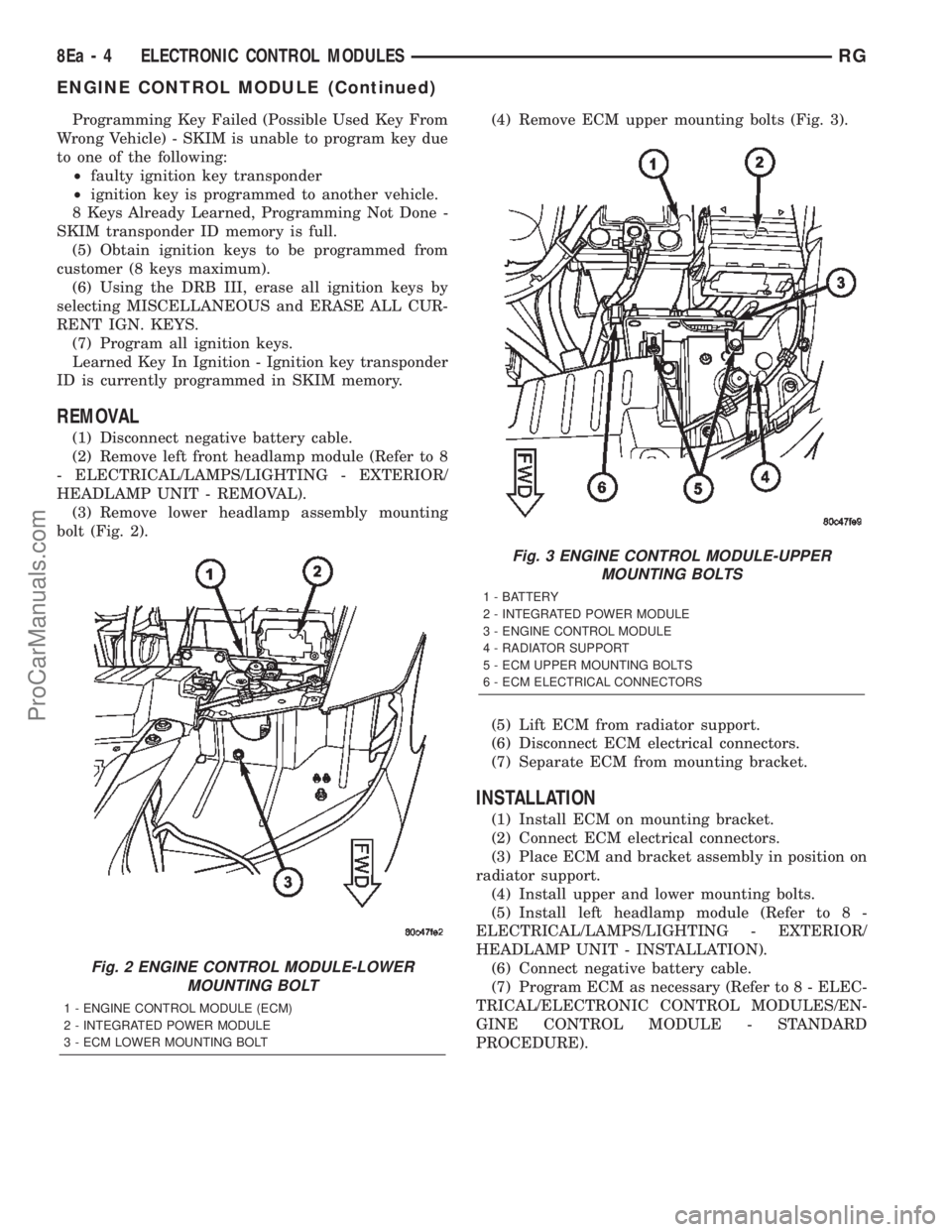
bolt (Fig. 2).(4) Remove ECM upper mounting bolts (Fig. 3).
(5) Lift ECM from radiator support.
(6) Disconnect ECM electrical connectors.
(7) Separate ECM from mounting bracket.
INSTALLATION
(1) Install ECM on mounting bracket.
(2) Connect ECM electrical connectors.
(3) Place ECM and bracket assembly in position on
radiator support.
(4) Install upper and lower mounting bolts.
(5) Install left headlamp module (Refer to 8 -
ELECTRICAL/LAMPS/LIGHTING - EXTERIOR/
HEADLAMP UNIT - INSTALLATION).
(6) Connect negative battery cable.
(7) Program ECM as necessary (Refer to 8 - ELEC-
TRICAL/ELECTRONIC CONTROL MODULES/EN-
GINE CONTROL MODULE - STANDARD
PROCEDURE).
Fig. 2 ENGINE CONTROL MODULE-LOWER
MOUNTING BOLT
1 - ENGINE CONTROL MODULE (ECM)
2 - INTEGRATED POWER MODULE
3 - ECM LOWER MOUNTING BOLT
Fig. 3 ENGINE CONTROL MODULE-UPPER
MOUNTING BOLTS
1 - BATTERY
2 - INTEGRATED POWER MODULE
3 - ENGINE CONTROL MODULE
4 - RADIATOR SUPPORT
5 - ECM UPPER MOUNTING BOLTS
6 - ECM ELECTRICAL CONNECTORS
8Ea - 4 ELECTRONIC CONTROL MODULESRG
ENGINE CONTROL MODULE (Continued)
ProCarManuals.com
Page 388 of 2399
CONVENTIONAL BATTERY CHARGING TIME TABLE
Charging
Amperage5 Amps10
Amps20 Amps
Open Circuit
VoltageHours Charging @ 21É C (70É
F)
12.25 to 12.49 6 hours 3 hours 1.5
hours
12.00 to 12.24 10 hours 5 hours 2.5
hours
10.00 to 11.99 14 hours 7 hours 3.5
hours
Below 10.00 18 hours 9 hours 4.5
hours
STANDARD PROCEDURE - OPEN-CIRCUIT
VOLTAGE TEST
A battery open-circuit voltage (no load) test will
show the approximate state-of-charge of a battery.
This test can be used if no other battery tester is
available.
Before proceeding with this test, completely charge
the battery. Refer to Standard Procedures for the
proper battery charging procedures.
(1) Before measuring the open-circuit voltage, the
surface charge must be removed from the battery.
Turn on the headlamps for fifteen seconds, then
allow up to five minutes for the battery voltage to
stabilize.
(2) Disconnect and isolate both battery cables, neg-
ative cable first.
(3) Using a voltmeter connected to the battery
posts (see the instructions provided by the manufac-
turer of the voltmeter), measure the open-circuit volt-
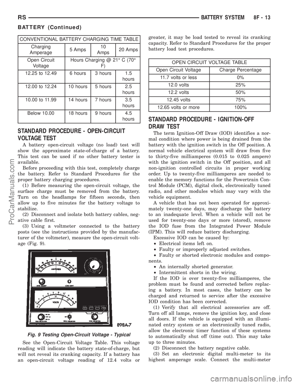
age (Fig. 9).
See the Open-Circuit Voltage Table. This voltage
reading will indicate the battery state-of-charge, but
will not reveal its cranking capacity. If a battery has
an open-circuit voltage reading of 12.4 volts orgreater, it may be load tested to reveal its cranking
capacity. Refer to Standard Procedures for the proper
battery load test procedures.
OPEN CIRCUIT VOLTAGE TABLE
Open Circuit Voltage Charge Percentage
11.7 volts or less 0%
12.0 volts 25%
12.2 volts 50%
12.45 volts 75%
12.65 volts or more 100%
STANDARD PROCEDURE - IGNITION-OFF
DRAW TEST
The term Ignition-Off Draw (IOD) identifies a nor-
mal condition where power is being drained from the
battery with the ignition switch in the Off position. A
normal vehicle electrical system will draw from five
to thirty-five milliamperes (0.015 to 0.025 ampere)
with the ignition switch in the Off position, and all
non-ignition controlled circuits in proper working
order. Up to twenty-five milliamperes are needed to
enable the memory functions for the Powertrain Con-
trol Module (PCM), digital clock, electronically tuned
radio, and other modules which may vary with the
vehicle equipment.
A vehicle that has not been operated for approxi-
mately twenty-one days, may discharge the battery
to an inadequate level. When a vehicle will not be
used for twenty-one days or more (stored), remove
the IOD fuse from the Integrated Power Module
(IPM). This will reduce battery discharging.
Excessive IOD can be caused by:
²Electrical items left on.
²Faulty or improperly adjusted switches.
²Faulty or shorted electronic modules and compo-
nents.
²An internally shorted generator.
²Intermittent shorts in the wiring.
If the IOD is over twenty-five milliamperes, the
problem must be found and corrected before replac-
ing a battery. In most cases, the battery can be
charged and returned to service after the excessive
IOD condition has been corrected.
(1) Verify that all electrical accessories are off.
Turn off all lamps, remove the ignition key, and close
all doors. If the vehicle is equipped with an illumi-
nated entry system or an electronically tuned radio,
allow the electronic timer function of these systems
to automatically shut off (time out). This may take
up to three minutes.
(2) Disconnect the battery negative cable.
(3) Set an electronic digital multi-meter to its
highest amperage scale. Connect the multi-meter
Fig. 9 Testing Open-Circuit Voltage - Typical
RSBATTERY SYSTEM8F-13
BATTERY (Continued)
ProCarManuals.com
Page 408 of 2399
tion. If that checks OK check for continuity between
PCM and the terminal 85. Repair open circuit as
required. If OK, the PCM may be defective.
SAFETY SWITCHES
For diagnostics of the Transmission Range Sensor,
refer to the Transaxle section for more information.
If equipped with Clutch Interlock/Upstop Switch,
refer to Diagnosis and Testing in the Clutch section.
IGNITION SWITCH
After testing starter solenoid and relay, test igni-
tion switch and wiring. Refer to the Ignition Section
or Wiring Diagrams for more information. Check all
wiring for opens or shorts, and all connectors for
being loose or corroded.
BATTERY
For battery diagnosis and testing, refer to the Bat-
tery section for procedures.
ALL RELATED WIRING AND CONNECTORS
Refer to Wiring Diagrams for more information.
DIAGNOSIS AND TESTING - FEED CIRCUIT
RESISTANCE TEST
Before proceeding with this operation, review Diag-
nostic Preparation and Starter Feed Circuit Tests.
The following operation will require a voltmeter,
accurate to 1/10 of a volt.
CAUTION: Ignition and Fuel systems must be dis-
abled to prevent engine start while performing the
following tests.
(1) To disable the Ignition and Fuel systems, dis-
connect the Automatic Shutdown Relay (ASD). The
ASD relay is located in the Power Distribution Cen-
ter (PDC). Refer to the PDC cover for proper relay
location.
(2) Gain access to battery terminals.
(3) With all wiring harnesses and components
properly connected, perform the following:
(a) Connect the negative lead of the voltmeter to
the battery negative post, and positive lead to the
battery negative cable clamp. Rotate and hold the
ignition switch in the START position. Observe the
voltmeter. If voltage is detected, correct poor con-
tact between cable clamp and post.
(b) Connect positive lead of the voltmeter to the
battery positive post, and negative lead to the bat-
tery positive cable clamp. Rotate and hold the igni-
tion switch key in the START position. Observe the
voltmeter. If voltage is detected, correct poor con-
tact between the cable clamp and post.(c) Connect negative lead of voltmeter to battery
negative terminal, and positive lead to engine
block near the battery cable attaching point.
Rotate and hold the ignition switch in the START
position. If voltage reads above 0.2 volt, correct
poor contact at ground cable attaching point. If
voltage reading is still above 0.2 volt after correct-
ing poor contacts, replace ground cable.
(4) Connect positive voltmeter lead to the starter
motor housing and the negative lead to the battery
negative terminal. Hold the ignition switch key in
the START position. If voltage reads above 0.2 volt,
correct poor starter to engine ground.
(a) Connect the positive voltmeter lead to the
battery positive terminal, and negative lead to bat-
tery cable terminal on starter solenoid. Rotate and
hold the ignition switch in the START position. If
voltage reads above 0.2 volt, correct poor contact at
battery cable to solenoid connection. If reading is
still above 0.2 volt after correcting poor contacts,
replace battery positive cable.
(b) If resistance tests do not detect feed circuit
failures, replace the starter motor.
DIAGNOSIS AND TESTING - FEED CIRCUIT
TEST
NOTE: The following results are based upon the
vehicle being at room temperature.
The following procedure will require a suitable
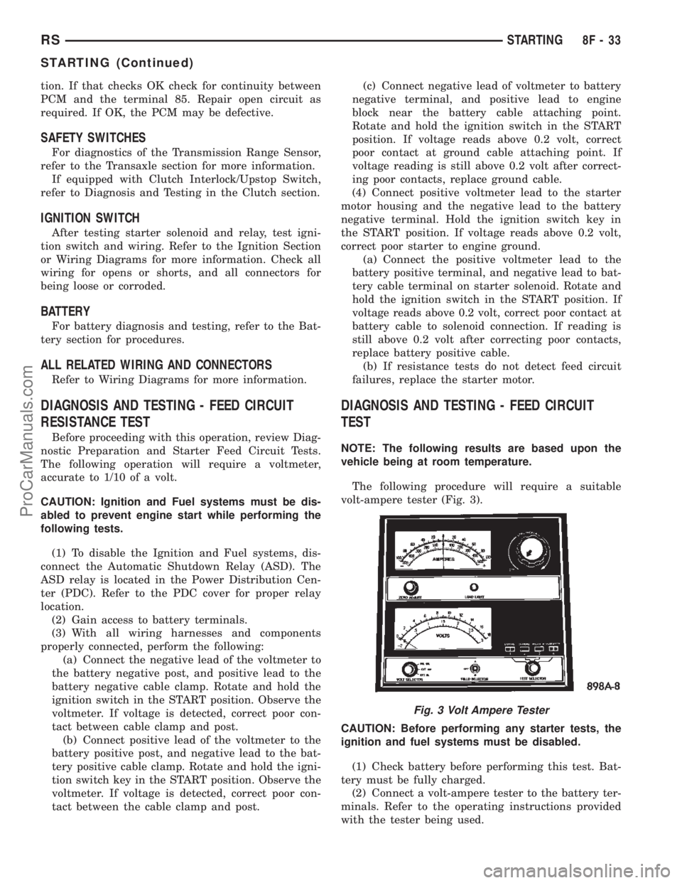
volt-ampere tester (Fig. 3).
CAUTION: Before performing any starter tests, the
ignition and fuel systems must be disabled.
(1) Check battery before performing this test. Bat-
tery must be fully charged.
(2) Connect a volt-ampere tester to the battery ter-
minals. Refer to the operating instructions provided
with the tester being used.
Fig. 3 Volt Ampere Tester
RSSTARTING8F-33
STARTING (Continued)
ProCarManuals.com
Page 425 of 2399
²Intermittent shorts in the wiring.
If the IOD is over twenty-five milliamperes, the
problem must be found and corrected before replac-
ing a battery. In most cases, the battery can be
charged and returned to service after the excessive
IOD condition has been corrected.
(1) Verify that all electrical accessories are off.
Turn off all lamps, remove the ignition key, and close
all doors. If the vehicle is equipped with an illumi-
nated entry system or an electronically tuned radio,
allow the electronic timer function of these systems
to automatically shut off (time out). This may take
up to three minutes.
(2) Disconnect the battery negative cable.
(3) Set an electronic digital multi-meter to its
highest amperage scale. Connect the multi-meter
between the disconnected battery negative cable ter-
minal clamp and the battery negative terminal post.
Make sure that the doors remain closed so that the
illuminated entry system is not activated. The multi-
meter amperage reading may remain high for up to
three minutes, or may not give any reading at all
while set in the highest amperage scale, depending
upon the electrical equipment in the vehicle. The
multi-meter leads must be securely clamped to the
battery negative cable terminal clamp and the bat-
tery negative terminal post. If continuity between the
battery negative terminal post and the negative cable
terminal clamp is lost during any part of the IOD
test, the electronic timer function will be activated
and all of the tests will have to be repeated.
(4) After about three minutes, the high-amperage
IOD reading on the multi-meter should become very
low or nonexistent, depending upon the electrical
equipment in the vehicle. If the amperage reading
remains high, remove and replace each fuse or circuit
breaker in the Integrated Power Module (IPM), one
at a time until the amperage reading becomes very
low, or nonexistent. Refer to the appropriate wiring
information in this service manual for complete Inte-
grated Power Module fuse, circuit breaker, and cir-
cuit identification. This will isolate each circuit and
identify the circuit that is the source of the high-am-
perage IOD. If the amperage reading remains high
after removing and replacing each fuse and circuit
breaker, disconnect the wire harness from the gener-
ator. If the amperage reading now becomes very low
or nonexistent, refer to Charging System for the
proper charging system diagnosis and testing proce-
dures. After the high-amperage IOD has been cor-
rected, switch the multi-meter to progressively lower
amperage scales and, if necessary, repeat the fuse
and circuit breaker remove-and-replace process to
identify and correct all sources of excessive IOD. It is
now safe to select the lowest milliampere scale of the
multi-meter to check the low-amperage IOD.CAUTION: Do not open any doors, or turn on any
electrical accessories with the lowest milliampere
scale selected, or the multi-meter may be damaged.
(5) Allow twenty minutes for the IOD to stabilize
and observe the multi-meter reading. The low-amper-
age IOD should not exceed twenty-five milliamperes
(0.025 ampere). If the current draw exceeds twenty-
five milliamperes, isolate each circuit using the fuse
and circuit breaker remove-and-replace process in
Step 4. The multi-meter reading will drop to within
the acceptable limit when the source of the excessive
current draw is disconnected. Repair this circuit as
required; whether a wiring short, incorrect switch
adjustment, or a component failure is at fault.
STANDARD PROCEDURE - CHECKING BATTERY
ELECTROLYTE LEVEL
The following procedure can be used to check the
electrolyte level in a low-maintenance lead-acid bat-
tery.
(1) Unscrew and remove the battery cell caps with
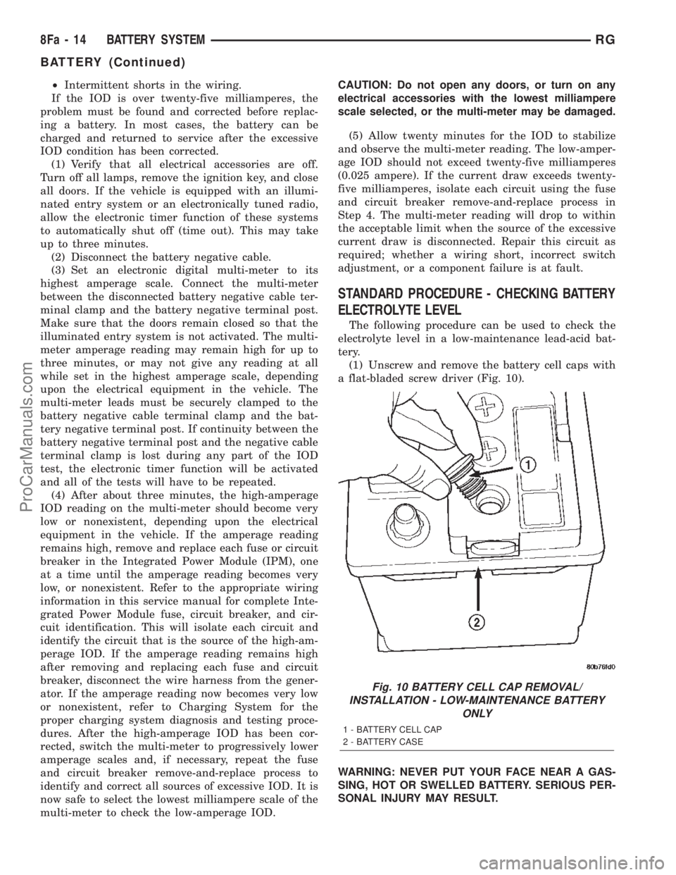
a flat-bladed screw driver (Fig. 10).
WARNING: NEVER PUT YOUR FACE NEAR A GAS-
SING, HOT OR SWELLED BATTERY. SERIOUS PER-
SONAL INJURY MAY RESULT.
Fig. 10 BATTERY CELL CAP REMOVAL/
INSTALLATION - LOW-MAINTENANCE BATTERY
ONLY
1 - BATTERY CELL CAP
2 - BATTERY CASE
8Fa - 14 BATTERY SYSTEMRG
BATTERY (Continued)
ProCarManuals.com
Page 447 of 2399
tion. If that checks OK check for continuity between
PCM and the terminal 85. Repair open circuit as
required. If OK, the PCM may be defective.
SAFETY SWITCHES
For diagnostics of the Transmission Range Sensor,
refer to the Transaxle section for more information.
If equipped with Clutch Interlock/Upstop Switch,
refer to Diagnosis and Testing in the Clutch section.
IGNITION SWITCH
After testing starter solenoid and relay, test igni-
tion switch and wiring. Refer to the Ignition Section
or Wiring Diagrams for more information. Check all
wiring for opens or shorts, and all connectors for
being loose or corroded.
BATTERY
For battery diagnosis and testing, refer to the Bat-
tery section for procedures.
ALL RELATED WIRING AND CONNECTORS
Refer to Wiring Diagrams for more information.
DIAGNOSIS AND TESTING - FEED CIRCUIT
RESISTANCE TEST
Before proceeding with this operation, review Diag-
nostic Preparation and Starter Feed Circuit Tests.
The following operation will require a voltmeter,
accurate to 1/10 of a volt.
CAUTION: Ignition and Fuel systems must be dis-
abled to prevent engine start while performing the
following tests.
(1) To disable the Ignition and Fuel systems, dis-
connect the Automatic Shutdown Relay (ASD). The
ASD relay is located in the Power Distribution Cen-
ter (PDC). Refer to the PDC cover for proper relay
location.
(2) Gain access to battery terminals.
(3) With all wiring harnesses and components
properly connected, perform the following:
(a) Connect the negative lead of the voltmeter to
the battery negative post, and positive lead to the
battery negative cable clamp. Rotate and hold the
ignition switch in the START position. Observe the
voltmeter. If voltage is detected, correct poor con-
tact between cable clamp and post.
(b) Connect positive lead of the voltmeter to the
battery positive post, and negative lead to the bat-
tery positive cable clamp. Rotate and hold the igni-
tion switch key in the START position. Observe the
voltmeter. If voltage is detected, correct poor con-
tact between the cable clamp and post.(c) Connect negative lead of voltmeter to battery
negative terminal, and positive lead to engine
block near the battery cable attaching point.
Rotate and hold the ignition switch in the START
position. If voltage reads above 0.2 volt, correct
poor contact at ground cable attaching point. If
voltage reading is still above 0.2 volt after correct-
ing poor contacts, replace ground cable.
(4) Connect positive voltmeter lead to the starter
motor housing and the negative lead to the battery
negative terminal. Hold the ignition switch key in
the START position. If voltage reads above 0.2 volt,
correct poor starter to engine ground.
(a) Connect the positive voltmeter lead to the
battery positive terminal, and negative lead to bat-
tery cable terminal on starter solenoid. Rotate and
hold the ignition switch in the START position. If
voltage reads above 0.2 volt, correct poor contact at
battery cable to solenoid connection. If reading is
still above 0.2 volt after correcting poor contacts,
replace battery positive cable.
(b) If resistance tests do not detect feed circuit
failures, replace the starter motor.
DIAGNOSIS AND TESTING - FEED CIRCUIT
TEST
NOTE: The following results are based upon the
vehicle being at room temperature.
The following procedure will require a suitable
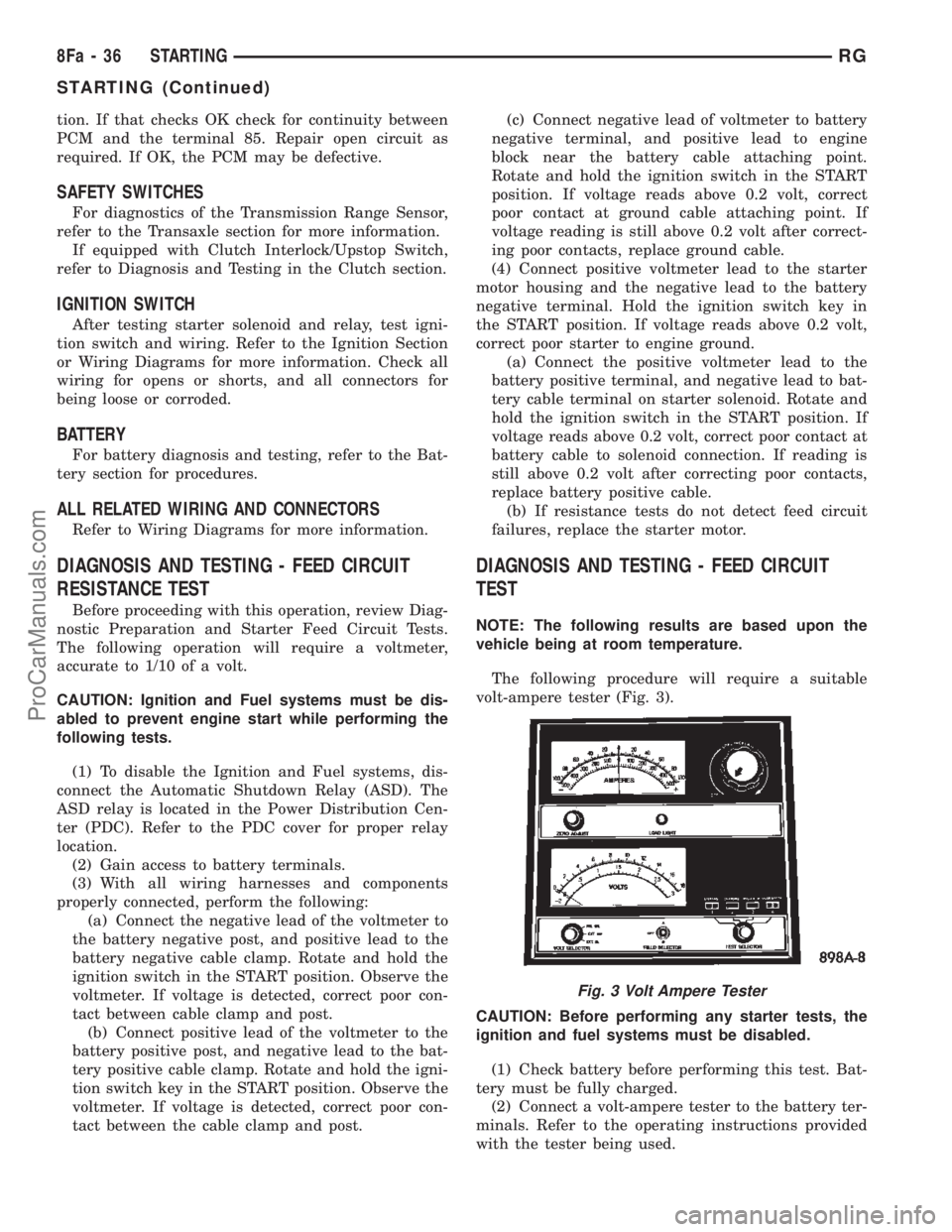
volt-ampere tester (Fig. 3).
CAUTION: Before performing any starter tests, the
ignition and fuel systems must be disabled.
(1) Check battery before performing this test. Bat-
tery must be fully charged.
(2) Connect a volt-ampere tester to the battery ter-
minals. Refer to the operating instructions provided
with the tester being used.
Fig. 3 Volt Ampere Tester
8Fa - 36 STARTINGRG
STARTING (Continued)
ProCarManuals.com
Page 483 of 2399
INSTALLATION - 3.3/3.8L
(1) Install coil over studs on bracket.
(2) Install 2 bolts to ignition coil.
(3) Install 2 nuts to the ignition coil studs. Tighten
nuts and bolts.
(4) Connect the electrical connector to the ignition
coil.
(5) Install the ignition cables to the ignition coil.
(6) Reposition the Power steering reservoir. Slide
bracket over the mounting stud (Fig. 11).
(7) Install 2 bolts to the Power steering reservoir
to intake manifold.
(8) Tighten the lower nut to stud on ignition coil
bracket.
(9) Install the throttle and speed control cables to
clip.
(10) Connect the negative battery cable.
KNOCK SENSOR
DESCRIPTION
The knock sensor threads into the cylinder block.
The knock sensor is designed to detect engine vibra-
tion that is caused by detonation.
OPERATION
When the knock sensor detects a knock in one of
the cylinders, it sends an input signal to the PCM. In
response, the PCM retards ignition timing for all cyl-
inders by a scheduled amount.
Knock sensors contain a piezoelectric material
which constantly vibrates and sends an input voltage
(signal) to the PCM while the engine operates. As the
intensity of the crystal's vibration increases, the
knock sensor output voltage also increases.
The voltage signal produced by the knock sensor
increases with the amplitude of vibration. The PCM
receives as an input the knock sensor voltage signal.
If the signal rises above a predetermined level, the
PCM will store that value in memory and retard
ignition timing to reduce engine knock. If the knock
sensor voltage exceeds a preset value, the PCM
retards ignition timing for all cylinders. It is not a
selective cylinder retard.
The PCM ignores knock sensor input during engine
idle conditions. Once the engine speed exceeds a
specified value, knock retard is allowed.
Knock retard uses its own short term and long
term memory program.
Long term memory stores previous detonation
information in its battery-backed RAM. The maxi-
mum authority that long term memory has over tim-
ing retard can be calibrated.
Short term memory is allowed to retard timing up
to a preset amount under all operating conditions (aslong as rpm is above the minimum rpm) except WOT.
The PCM, using short term memory, can respond
quickly to retard timing when engine knock is
detected. Short term memory is lost any time the
ignition key is turned off.
NOTE: Over or under tightening affects knock sen-
sor performance, possibly causing improper spark
control.
REMOVAL
REMOVAL - 2.4L
The knock sensor threads into the side of the cyl-
inder block in front of the starter (Fig. 12).
(1) Disconnect electrical connector from knock sen-
sor.
(2) Use a crow foot socket to remove the knock
sensors.
REMOVAL - 3.8L
The knock sensor threads into the side of the cyl-
inder block in the rear.
(1) Disconnect the negative battery cable.
(2) Raise vehicle and support.
(3) On All Wheel Drive vehicles remove the PTU
(Power Transfer Unit), refer to the Transmission sec-
tion for more information.
(4) Disconnect electrical connector from knock sen-
sor.
(5) Use a crow foot socket to remove the knock
sensor.
INSTALLATION
INSTALLATION - 2.4L
The knock sensor threads into the side of the cyl-
inder block in front of the starter (Fig. 12).
(1) Install knock sensor. Tighten knock sensor to
10 N´m (7 ft. lbs.) torque.Over or under tighten-
ing effects knock sensor performance, possibly
causing improper spark control.
(2) Attach electrical connector to knock sensor.
INSTALLATION - 3.8L
The knock sensor threads into the side of the cyl-
inder block in the rear.
(1) Install knock sensor. Tighten knock sensor to
10 N´m (7 ft. lbs.) torque.Over or under tighten-
ing effects knock sensor performance, possibly
causing improper spark control.
(2) Attach electrical connector to knock sensor.
8I - 8 IGNITION CONTROLRS
IGNITION COIL (Continued)
ProCarManuals.com