radiator CHRYSLER CARAVAN 2002 Workshop Manual
[x] Cancel search | Manufacturer: CHRYSLER, Model Year: 2002, Model line: CARAVAN, Model: CHRYSLER CARAVAN 2002Pages: 2399, PDF Size: 57.96 MB
Page 318 of 2399
RADIATOR FAN RELAY
DESCRIPTION
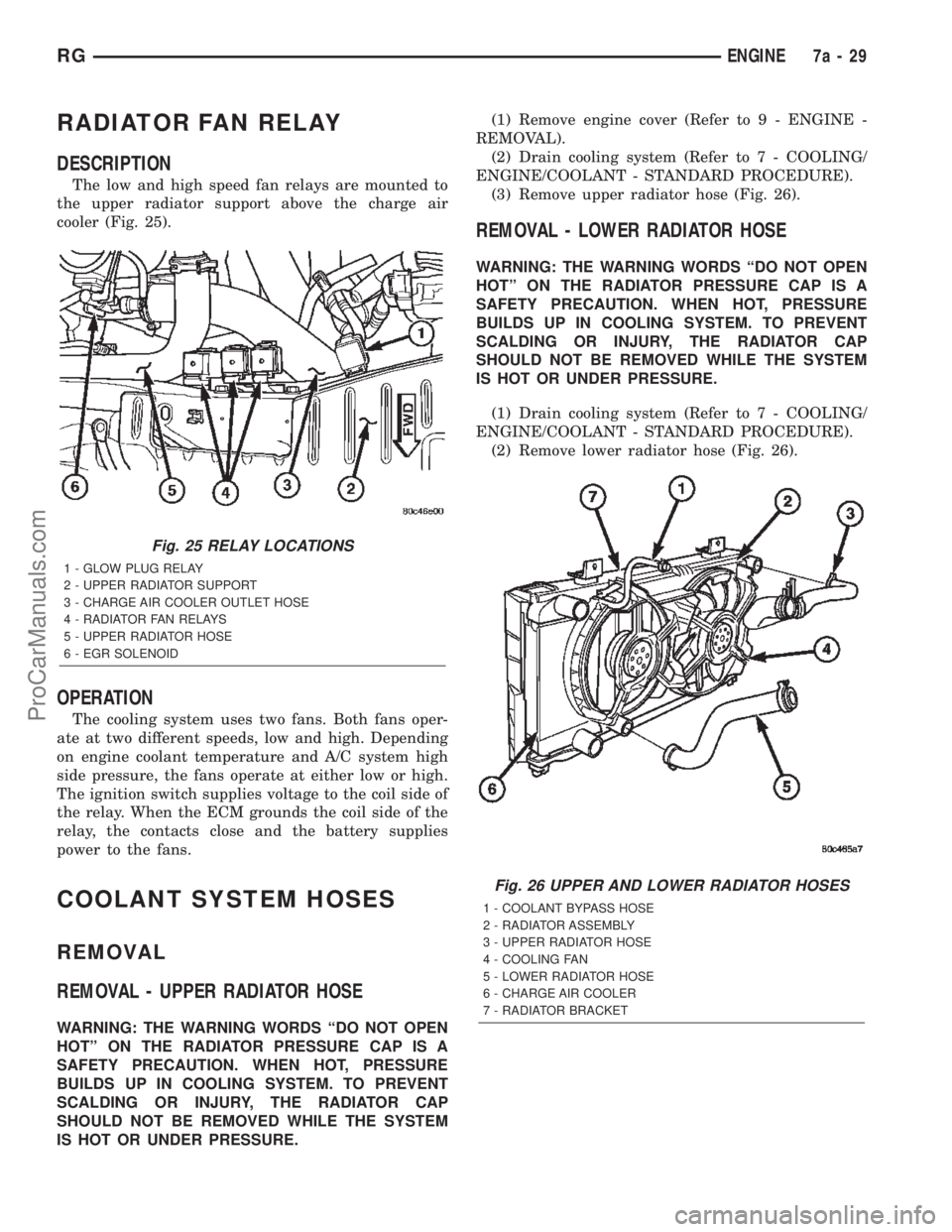
The low and high speed fan relays are mounted to
the upper radiator support above the charge air
cooler (Fig. 25).
OPERATION
The cooling system uses two fans. Both fans oper-
ate at two different speeds, low and high. Depending
on engine coolant temperature and A/C system high
side pressure, the fans operate at either low or high.
The ignition switch supplies voltage to the coil side of
the relay. When the ECM grounds the coil side of the
relay, the contacts close and the battery supplies
power to the fans.
COOLANT SYSTEM HOSES
REMOVAL
REMOVAL - UPPER RADIATOR HOSE
WARNING: THE WARNING WORDS ªDO NOT OPEN
HOTº ON THE RADIATOR PRESSURE CAP IS A
SAFETY PRECAUTION. WHEN HOT, PRESSURE
BUILDS UP IN COOLING SYSTEM. TO PREVENT
SCALDING OR INJURY, THE RADIATOR CAP
SHOULD NOT BE REMOVED WHILE THE SYSTEM
IS HOT OR UNDER PRESSURE.(1) Remove engine cover (Refer to 9 - ENGINE -
REMOVAL).
(2) Drain cooling system (Refer to 7 - COOLING/
ENGINE/COOLANT - STANDARD PROCEDURE).
(3) Remove upper radiator hose (Fig. 26).
REMOVAL - LOWER RADIATOR HOSE
WARNING: THE WARNING WORDS ªDO NOT OPEN
HOTº ON THE RADIATOR PRESSURE CAP IS A
SAFETY PRECAUTION. WHEN HOT, PRESSURE
BUILDS UP IN COOLING SYSTEM. TO PREVENT
SCALDING OR INJURY, THE RADIATOR CAP
SHOULD NOT BE REMOVED WHILE THE SYSTEM
IS HOT OR UNDER PRESSURE.
(1) Drain cooling system (Refer to 7 - COOLING/
ENGINE/COOLANT - STANDARD PROCEDURE).
(2) Remove lower radiator hose (Fig. 26).
Fig. 25 RELAY LOCATIONS
1 - GLOW PLUG RELAY
2 - UPPER RADIATOR SUPPORT
3 - CHARGE AIR COOLER OUTLET HOSE
4 - RADIATOR FAN RELAYS
5 - UPPER RADIATOR HOSE
6 - EGR SOLENOID
Fig. 26 UPPER AND LOWER RADIATOR HOSES
1 - COOLANT BYPASS HOSE
2 - RADIATOR ASSEMBLY
3 - UPPER RADIATOR HOSE
4 - COOLING FAN
5 - LOWER RADIATOR HOSE
6 - CHARGE AIR COOLER
7 - RADIATOR BRACKET
RGENGINE7a-29
ProCarManuals.com
Page 319 of 2399
REMOVAL - COOLANT BYPASS HOSE
WARNING: THE WARNING WORDS ªDO NOT OPEN
HOTº ON THE RADIATOR PRESSURE CAP IS A
SAFETY PRECAUTION. WHEN HOT, PRESSURE
BUILDS UP IN COOLING SYSTEM. TO PREVENT
SCALDING OR INJURY, THE RADIATOR CAP
SHOULD NOT BE REMOVED WHILE THE SYSTEM
IS HOT OR UNDER PRESSURE.
(1) Drain cooling system (Refer to 7 - COOLING/
ENGINE/COOLANT - STANDARD PROCEDURE).
(2) Remove the coolant bypass hose (Fig. 26).
INSTALLATION
INSTALLATION - UPPER RADIATOR HOSE
(1) Install upper radiator hose (Fig. 26).(2) Refill cooling system (Refer to 7 - COOLING/
ENGINE/COOLANT - STANDARD PROCEDURE).
(3) Install engine cover (Refer to 9 - ENGINE -
INSTALLATION).
INSTALLATION - LOWER RADIATOR HOSE
(1) Install lower radiator hose (Fig. 26).
(2) Refill cooling system (Refer to 7 - COOLING/
ENGINE/COOLANT - STANDARD PROCEDURE).
INSTALLATION - COOLANT BYPASS HOSE
(1) Install cooling system bypass hose (Fig. 26).
(2) Refill cooling system (Refer to 7 - COOLING/
ENGINE/COOLANT - STANDARD PROCEDURE).
7a - 30 ENGINERG
COOLANT SYSTEM HOSES (Continued)
ProCarManuals.com
Page 358 of 2399
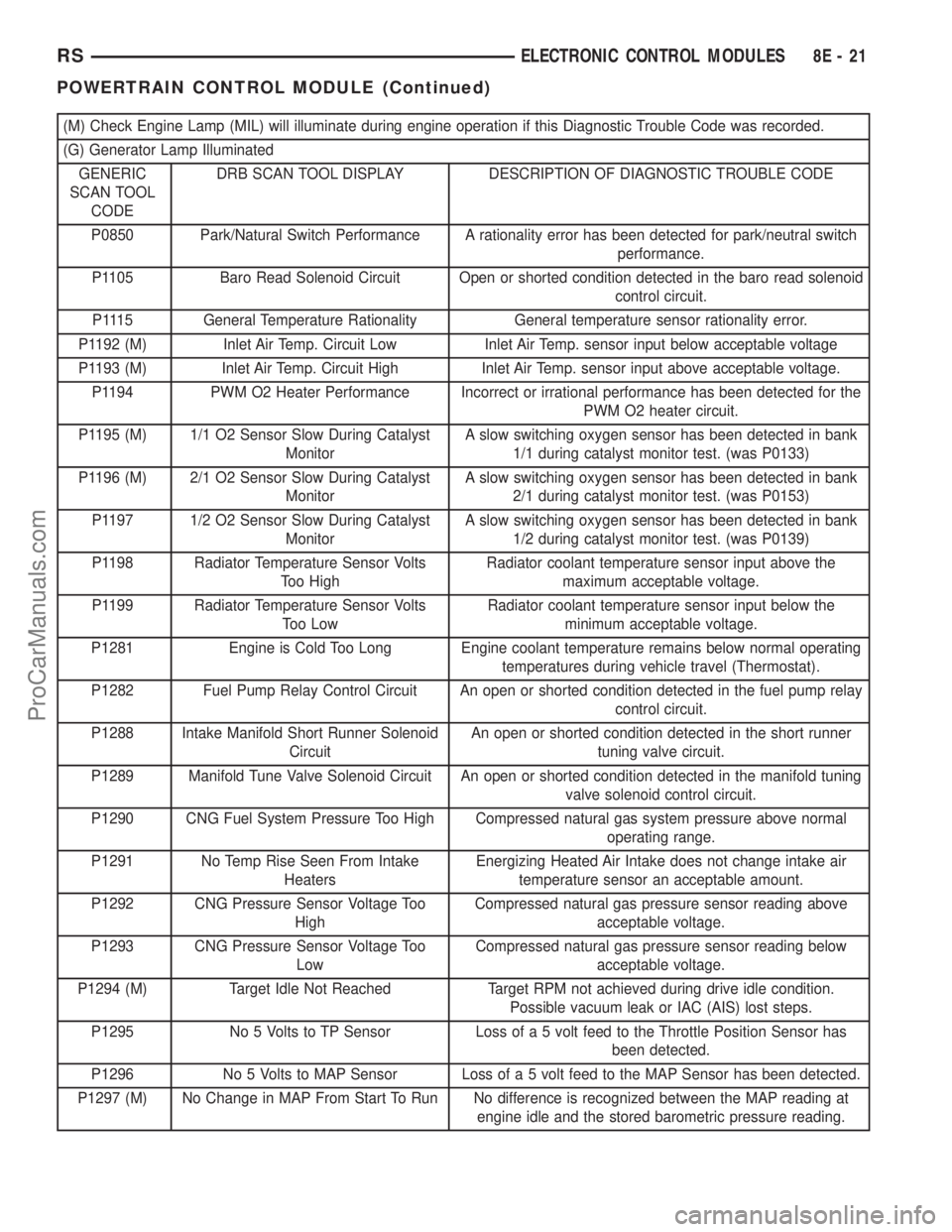
(M) Check Engine Lamp (MIL) will illuminate during engine operation if this Diagnostic Trouble Code was recorded.
(G) Generator Lamp Illuminated
GENERIC
SCAN TOOL
CODEDRB SCAN TOOL DISPLAY DESCRIPTION OF DIAGNOSTIC TROUBLE CODE
P0850 Park/Natural Switch Performance A rationality error has been detected for park/neutral switch
performance.
P1105 Baro Read Solenoid Circuit Open or shorted condition detected in the baro read solenoid
control circuit.
P1115 General Temperature Rationality General temperature sensor rationality error.
P1192 (M) Inlet Air Temp. Circuit Low Inlet Air Temp. sensor input below acceptable voltage
P1193 (M) Inlet Air Temp. Circuit High Inlet Air Temp. sensor input above acceptable voltage.
P1194 PWM O2 Heater Performance Incorrect or irrational performance has been detected for the
PWM O2 heater circuit.
P1195 (M) 1/1 O2 Sensor Slow During Catalyst
MonitorA slow switching oxygen sensor has been detected in bank
1/1 during catalyst monitor test. (was P0133)
P1196 (M) 2/1 O2 Sensor Slow During Catalyst
MonitorA slow switching oxygen sensor has been detected in bank
2/1 during catalyst monitor test. (was P0153)
P1197 1/2 O2 Sensor Slow During Catalyst
MonitorA slow switching oxygen sensor has been detected in bank
1/2 during catalyst monitor test. (was P0139)
P1198 Radiator Temperature Sensor Volts
Too HighRadiator coolant temperature sensor input above the
maximum acceptable voltage.
P1199 Radiator Temperature Sensor Volts
Too LowRadiator coolant temperature sensor input below the
minimum acceptable voltage.
P1281 Engine is Cold Too Long Engine coolant temperature remains below normal operating
temperatures during vehicle travel (Thermostat).
P1282 Fuel Pump Relay Control Circuit An open or shorted condition detected in the fuel pump relay
control circuit.
P1288 Intake Manifold Short Runner Solenoid
CircuitAn open or shorted condition detected in the short runner
tuning valve circuit.
P1289 Manifold Tune Valve Solenoid Circuit An open or shorted condition detected in the manifold tuning
valve solenoid control circuit.
P1290 CNG Fuel System Pressure Too High Compressed natural gas system pressure above normal
operating range.
P1291 No Temp Rise Seen From Intake
HeatersEnergizing Heated Air Intake does not change intake air
temperature sensor an acceptable amount.
P1292 CNG Pressure Sensor Voltage Too
HighCompressed natural gas pressure sensor reading above
acceptable voltage.
P1293 CNG Pressure Sensor Voltage Too
LowCompressed natural gas pressure sensor reading below
acceptable voltage.
P1294 (M) Target Idle Not Reached Target RPM not achieved during drive idle condition.
Possible vacuum leak or IAC (AIS) lost steps.
P1295 No 5 Volts to TP Sensor Loss of a 5 volt feed to the Throttle Position Sensor has
been detected.
P1296 No 5 Volts to MAP Sensor Loss of a 5 volt feed to the MAP Sensor has been detected.
P1297 (M) No Change in MAP From Start To Run No difference is recognized between the MAP reading at
engine idle and the stored barometric pressure reading.
RSELECTRONIC CONTROL MODULES8E-21
POWERTRAIN CONTROL MODULE (Continued)
ProCarManuals.com
Page 359 of 2399
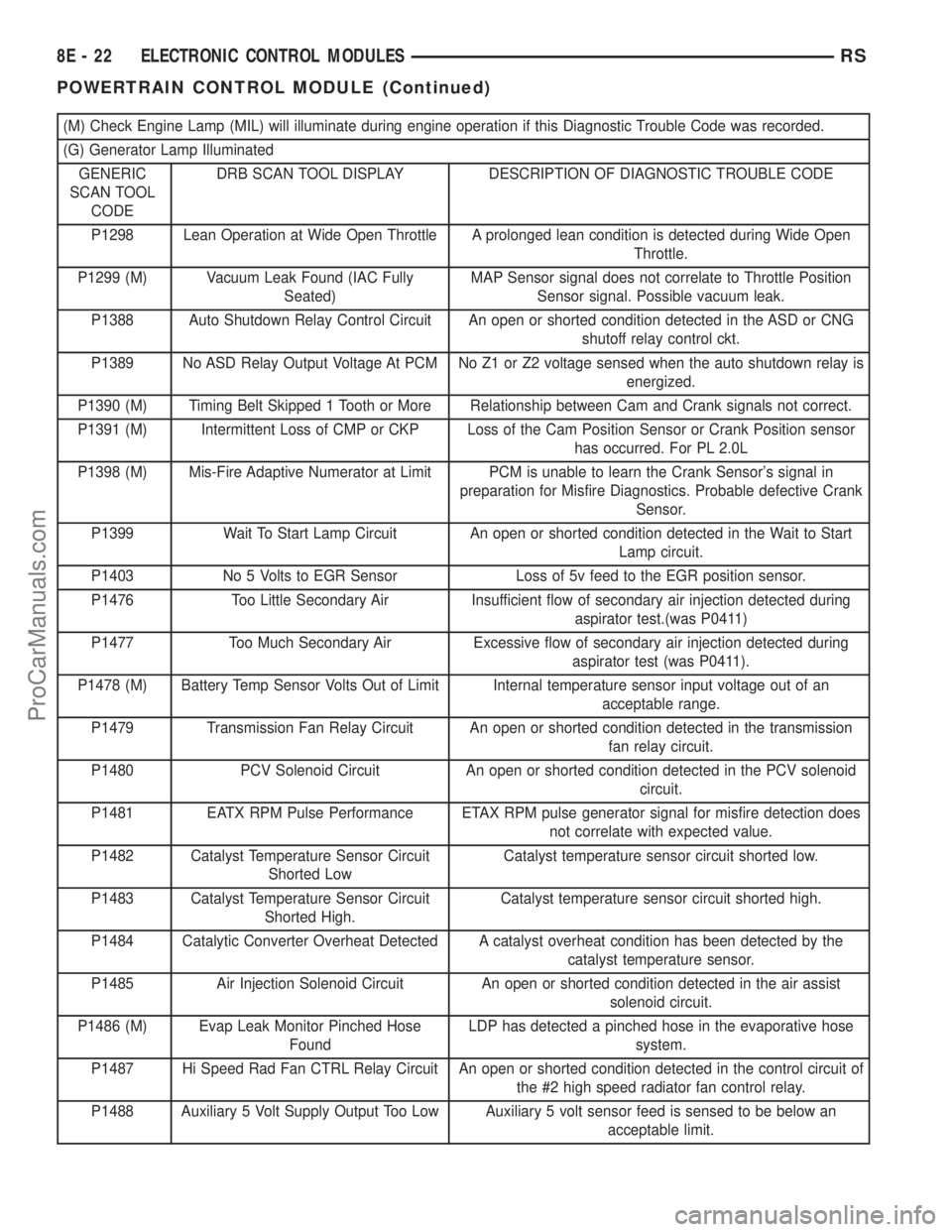
(M) Check Engine Lamp (MIL) will illuminate during engine operation if this Diagnostic Trouble Code was recorded.
(G) Generator Lamp Illuminated
GENERIC
SCAN TOOL
CODEDRB SCAN TOOL DISPLAY DESCRIPTION OF DIAGNOSTIC TROUBLE CODE
P1298 Lean Operation at Wide Open Throttle A prolonged lean condition is detected during Wide Open
Throttle.
P1299 (M) Vacuum Leak Found (IAC Fully
Seated)MAP Sensor signal does not correlate to Throttle Position
Sensor signal. Possible vacuum leak.
P1388 Auto Shutdown Relay Control Circuit An open or shorted condition detected in the ASD or CNG
shutoff relay control ckt.
P1389 No ASD Relay Output Voltage At PCM No Z1 or Z2 voltage sensed when the auto shutdown relay is
energized.
P1390 (M) Timing Belt Skipped 1 Tooth or More Relationship between Cam and Crank signals not correct.
P1391 (M) Intermittent Loss of CMP or CKP Loss of the Cam Position Sensor or Crank Position sensor
has occurred. For PL 2.0L
P1398 (M) Mis-Fire Adaptive Numerator at Limit PCM is unable to learn the Crank Sensor's signal in
preparation for Misfire Diagnostics. Probable defective Crank
Sensor.
P1399 Wait To Start Lamp Circuit An open or shorted condition detected in the Wait to Start
Lamp circuit.
P1403 No 5 Volts to EGR Sensor Loss of 5v feed to the EGR position sensor.
P1476 Too Little Secondary Air Insufficient flow of secondary air injection detected during
aspirator test.(was P0411)
P1477 Too Much Secondary Air Excessive flow of secondary air injection detected during
aspirator test (was P0411).
P1478 (M) Battery Temp Sensor Volts Out of Limit Internal temperature sensor input voltage out of an
acceptable range.
P1479 Transmission Fan Relay Circuit An open or shorted condition detected in the transmission
fan relay circuit.
P1480 PCV Solenoid Circuit An open or shorted condition detected in the PCV solenoid
circuit.
P1481 EATX RPM Pulse Performance ETAX RPM pulse generator signal for misfire detection does
not correlate with expected value.
P1482 Catalyst Temperature Sensor Circuit
Shorted LowCatalyst temperature sensor circuit shorted low.
P1483 Catalyst Temperature Sensor Circuit
Shorted High.Catalyst temperature sensor circuit shorted high.
P1484 Catalytic Converter Overheat Detected A catalyst overheat condition has been detected by the
catalyst temperature sensor.
P1485 Air Injection Solenoid Circuit An open or shorted condition detected in the air assist
solenoid circuit.
P1486 (M) Evap Leak Monitor Pinched Hose
FoundLDP has detected a pinched hose in the evaporative hose
system.
P1487 Hi Speed Rad Fan CTRL Relay Circuit An open or shorted condition detected in the control circuit of
the #2 high speed radiator fan control relay.
P1488 Auxiliary 5 Volt Supply Output Too Low Auxiliary 5 volt sensor feed is sensed to be below an
acceptable limit.
8E - 22 ELECTRONIC CONTROL MODULESRS
POWERTRAIN CONTROL MODULE (Continued)
ProCarManuals.com
Page 360 of 2399
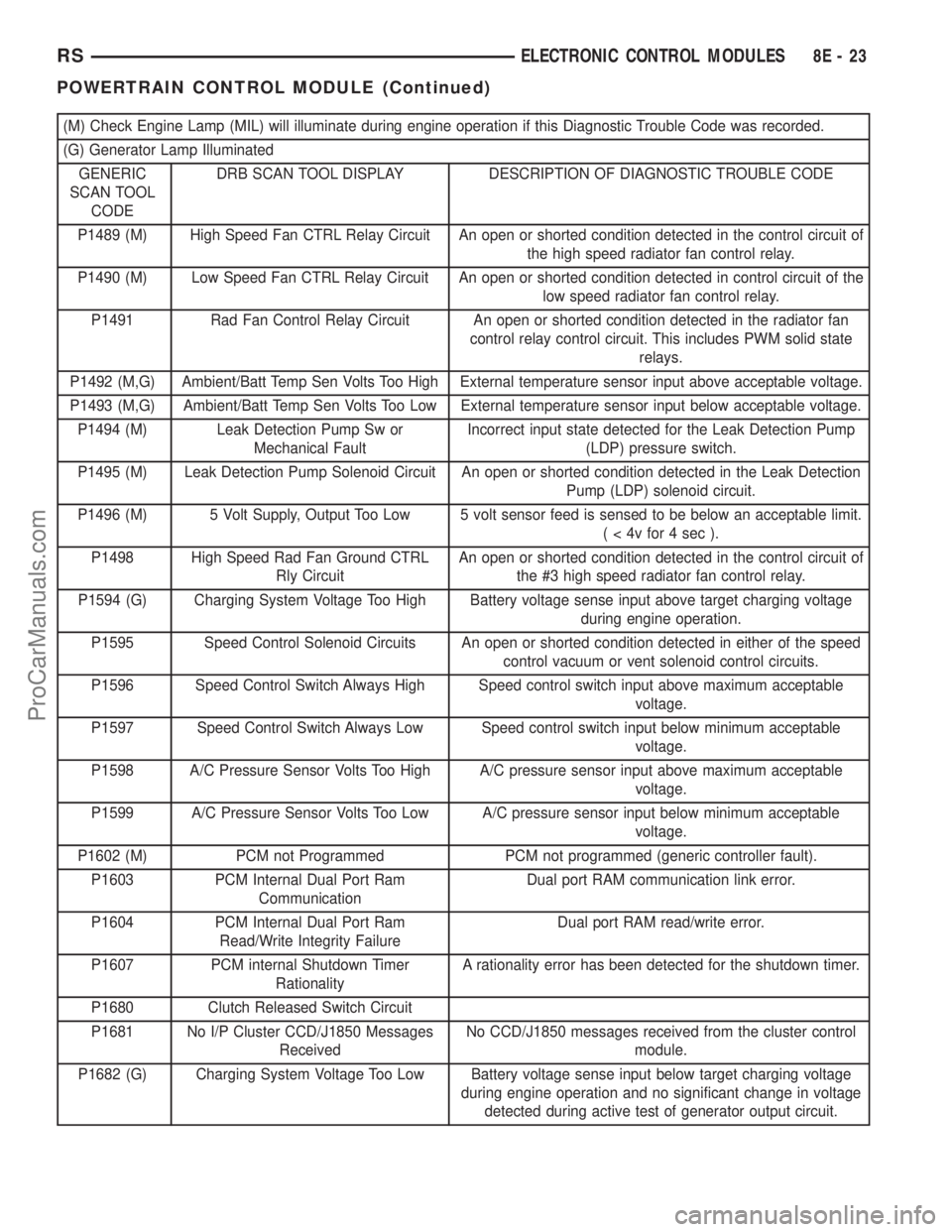
(M) Check Engine Lamp (MIL) will illuminate during engine operation if this Diagnostic Trouble Code was recorded.
(G) Generator Lamp Illuminated
GENERIC
SCAN TOOL
CODEDRB SCAN TOOL DISPLAY DESCRIPTION OF DIAGNOSTIC TROUBLE CODE
P1489 (M) High Speed Fan CTRL Relay Circuit An open or shorted condition detected in the control circuit of
the high speed radiator fan control relay.
P1490 (M) Low Speed Fan CTRL Relay Circuit An open or shorted condition detected in control circuit of the
low speed radiator fan control relay.
P1491 Rad Fan Control Relay Circuit An open or shorted condition detected in the radiator fan
control relay control circuit. This includes PWM solid state
relays.
P1492 (M,G) Ambient/Batt Temp Sen Volts Too High External temperature sensor input above acceptable voltage.
P1493 (M,G) Ambient/Batt Temp Sen Volts Too Low External temperature sensor input below acceptable voltage.
P1494 (M) Leak Detection Pump Sw or
Mechanical FaultIncorrect input state detected for the Leak Detection Pump
(LDP) pressure switch.
P1495 (M) Leak Detection Pump Solenoid Circuit An open or shorted condition detected in the Leak Detection
Pump (LDP) solenoid circuit.
P1496 (M) 5 Volt Supply, Output Too Low 5 volt sensor feed is sensed to be below an acceptable limit.
( < 4v for 4 sec ).
P1498 High Speed Rad Fan Ground CTRL
Rly CircuitAn open or shorted condition detected in the control circuit of
the #3 high speed radiator fan control relay.
P1594 (G) Charging System Voltage Too High Battery voltage sense input above target charging voltage
during engine operation.
P1595 Speed Control Solenoid Circuits An open or shorted condition detected in either of the speed
control vacuum or vent solenoid control circuits.
P1596 Speed Control Switch Always High Speed control switch input above maximum acceptable
voltage.
P1597 Speed Control Switch Always Low Speed control switch input below minimum acceptable
voltage.
P1598 A/C Pressure Sensor Volts Too High A/C pressure sensor input above maximum acceptable
voltage.
P1599 A/C Pressure Sensor Volts Too Low A/C pressure sensor input below minimum acceptable
voltage.
P1602 (M) PCM not Programmed PCM not programmed (generic controller fault).
P1603 PCM Internal Dual Port Ram
CommunicationDual port RAM communication link error.
P1604 PCM Internal Dual Port Ram
Read/Write Integrity FailureDual port RAM read/write error.
P1607 PCM internal Shutdown Timer
RationalityA rationality error has been detected for the shutdown timer.
P1680 Clutch Released Switch Circuit
P1681 No I/P Cluster CCD/J1850 Messages
ReceivedNo CCD/J1850 messages received from the cluster control
module.
P1682 (G) Charging System Voltage Too Low Battery voltage sense input below target charging voltage
during engine operation and no significant change in voltage
detected during active test of generator output circuit.
RSELECTRONIC CONTROL MODULES8E-23
POWERTRAIN CONTROL MODULE (Continued)
ProCarManuals.com
Page 372 of 2399
ELECTRONIC CONTROL MODULES
TABLE OF CONTENTS
page page
ENGINE CONTROL MODULE
DESCRIPTION..........................1
OPERATION............................1
STANDARD PROCEDURE - PCM/ECM/SKIM
PROGRAMMING - DIESEL...............2REMOVAL.............................4
INSTALLATION..........................4
ENGINE CONTROL MODULE
DESCRIPTION
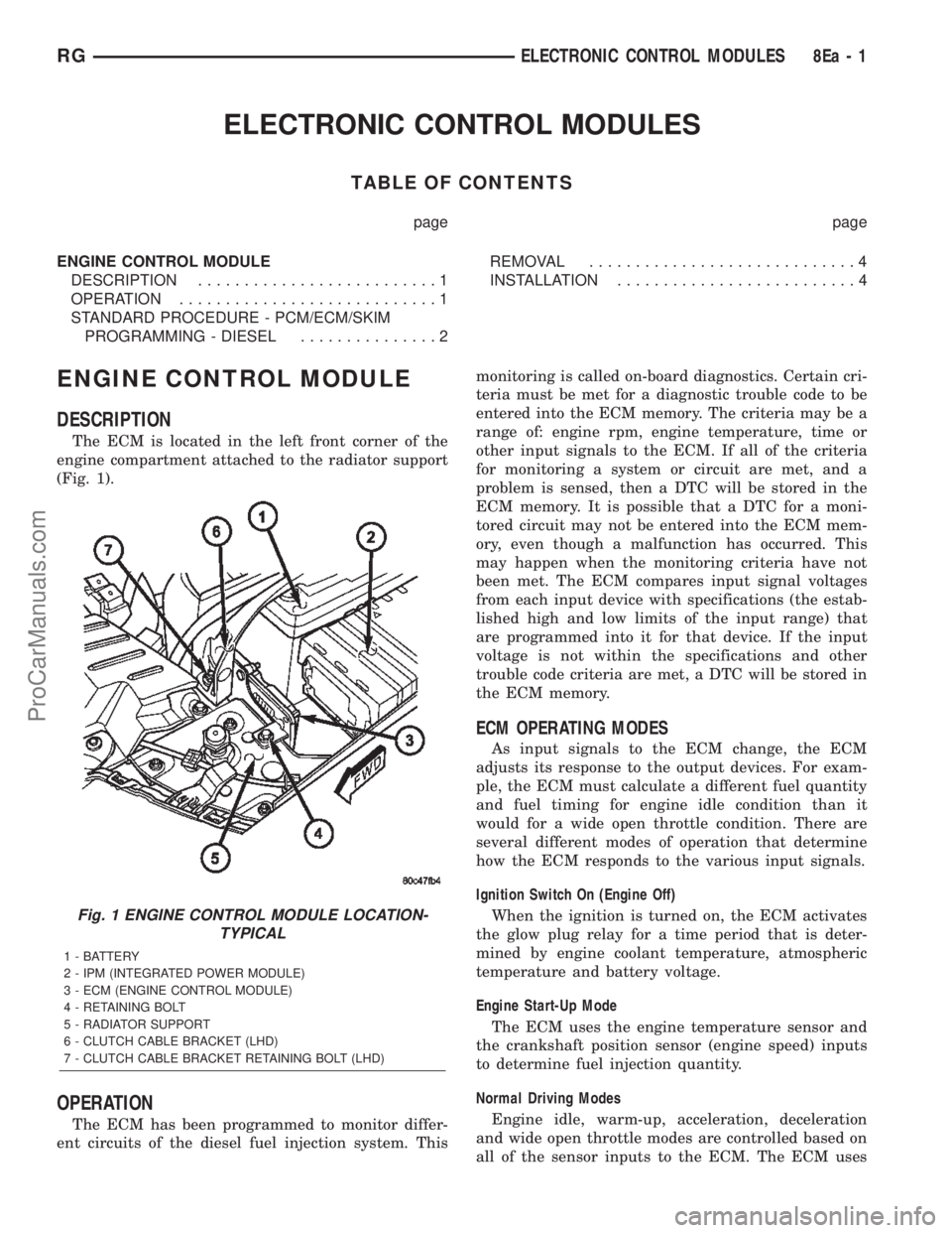
The ECM is located in the left front corner of the
engine compartment attached to the radiator support
(Fig. 1).
OPERATION
The ECM has been programmed to monitor differ-
ent circuits of the diesel fuel injection system. Thismonitoring is called on-board diagnostics. Certain cri-
teria must be met for a diagnostic trouble code to be
entered into the ECM memory. The criteria may be a
range of: engine rpm, engine temperature, time or
other input signals to the ECM. If all of the criteria
for monitoring a system or circuit are met, and a
problem is sensed, then a DTC will be stored in the
ECM memory. It is possible that a DTC for a moni-
tored circuit may not be entered into the ECM mem-
ory, even though a malfunction has occurred. This
may happen when the monitoring criteria have not
been met. The ECM compares input signal voltages
from each input device with specifications (the estab-
lished high and low limits of the input range) that
are programmed into it for that device. If the input
voltage is not within the specifications and other
trouble code criteria are met, a DTC will be stored in
the ECM memory.
ECM OPERATING MODES
As input signals to the ECM change, the ECM
adjusts its response to the output devices. For exam-
ple, the ECM must calculate a different fuel quantity
and fuel timing for engine idle condition than it
would for a wide open throttle condition. There are
several different modes of operation that determine
how the ECM responds to the various input signals.
Ignition Switch On (Engine Off)
When the ignition is turned on, the ECM activates
the glow plug relay for a time period that is deter-
mined by engine coolant temperature, atmospheric
temperature and battery voltage.
Engine Start-Up Mode
The ECM uses the engine temperature sensor and
the crankshaft position sensor (engine speed) inputs
to determine fuel injection quantity.
Normal Driving Modes
Engine idle, warm-up, acceleration, deceleration
and wide open throttle modes are controlled based on
all of the sensor inputs to the ECM. The ECM uses
Fig. 1 ENGINE CONTROL MODULE LOCATION-
TYPICAL
1 - BATTERY
2 - IPM (INTEGRATED POWER MODULE)
3 - ECM (ENGINE CONTROL MODULE)
4 - RETAINING BOLT
5 - RADIATOR SUPPORT
6 - CLUTCH CABLE BRACKET (LHD)
7 - CLUTCH CABLE BRACKET RETAINING BOLT (LHD)
RGELECTRONIC CONTROL MODULES8Ea-1
ProCarManuals.com
Page 375 of 2399
Programming Key Failed (Possible Used Key From
Wrong Vehicle) - SKIM is unable to program key due
to one of the following:
²faulty ignition key transponder
²ignition key is programmed to another vehicle.
8 Keys Already Learned, Programming Not Done -
SKIM transponder ID memory is full.
(5) Obtain ignition keys to be programmed from
customer (8 keys maximum).
(6) Using the DRB III, erase all ignition keys by
selecting MISCELLANEOUS and ERASE ALL CUR-
RENT IGN. KEYS.
(7) Program all ignition keys.
Learned Key In Ignition - Ignition key transponder
ID is currently programmed in SKIM memory.
REMOVAL
(1) Disconnect negative battery cable.
(2) Remove left front headlamp module (Refer to 8
- ELECTRICAL/LAMPS/LIGHTING - EXTERIOR/
HEADLAMP UNIT - REMOVAL).
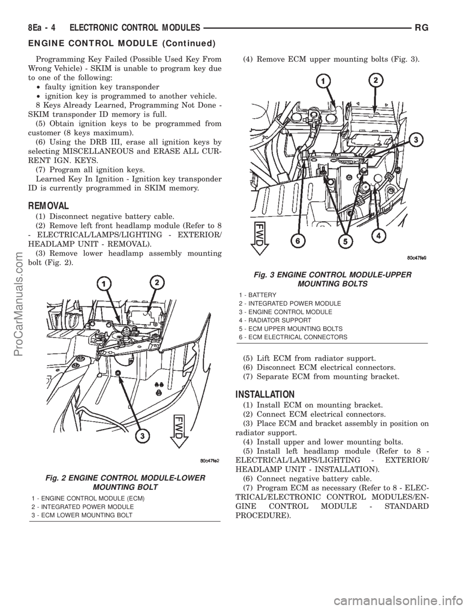
(3) Remove lower headlamp assembly mounting
bolt (Fig. 2).(4) Remove ECM upper mounting bolts (Fig. 3).
(5) Lift ECM from radiator support.
(6) Disconnect ECM electrical connectors.
(7) Separate ECM from mounting bracket.
INSTALLATION
(1) Install ECM on mounting bracket.
(2) Connect ECM electrical connectors.
(3) Place ECM and bracket assembly in position on
radiator support.
(4) Install upper and lower mounting bolts.
(5) Install left headlamp module (Refer to 8 -
ELECTRICAL/LAMPS/LIGHTING - EXTERIOR/
HEADLAMP UNIT - INSTALLATION).
(6) Connect negative battery cable.
(7) Program ECM as necessary (Refer to 8 - ELEC-
TRICAL/ELECTRONIC CONTROL MODULES/EN-
GINE CONTROL MODULE - STANDARD
PROCEDURE).
Fig. 2 ENGINE CONTROL MODULE-LOWER
MOUNTING BOLT
1 - ENGINE CONTROL MODULE (ECM)
2 - INTEGRATED POWER MODULE
3 - ECM LOWER MOUNTING BOLT
Fig. 3 ENGINE CONTROL MODULE-UPPER
MOUNTING BOLTS
1 - BATTERY
2 - INTEGRATED POWER MODULE
3 - ENGINE CONTROL MODULE
4 - RADIATOR SUPPORT
5 - ECM UPPER MOUNTING BOLTS
6 - ECM ELECTRICAL CONNECTORS
8Ea - 4 ELECTRONIC CONTROL MODULESRG
ENGINE CONTROL MODULE (Continued)
ProCarManuals.com
Page 473 of 2399
FUSE BLOWN
(1) Verify condition of battery terminals and volt-
age, (Refer to 8 - ELECTRICAL/BATTERY SYSTEM
- DIAGNOSIS AND TESTING). If battery connec-
tions and battery charge is OK proceed to Step 2.
(2) Using a voltmeter, test for battery voltage at
both sides of horn fuse 7. If voltage is OK, on both
sides of fuse, proceed to Fuse OK. If voltage is OK,
on one side of fuse, the fuse is blown, proceed to Step
3.
(3) Using a suitable ammeter in place of the fuse,
test amperage draw of the horn circuit. If amperage
draw is greater than 20 amps without the horn
switch depressed, a grounded circuit exists between
the fuse and the horn relay. Proceed to Step 4. If
amperage draw is greater than 20 amps with the
horn switch depressed, a grounded circuit exists
between the horn relay and the horn. Proceed to step
Step 5.
(4) Remove the horn relay from the IPM. If the
amperage draw drops to 0 amps, the horn switch or
circuit is shorted. If the amperage draw does not
drop to 0 amps, repair short at the IPM.
(5) Disengage a wire connector from one of the
horns. If amperage drops and the connected horn
sounds, replace the faulty horn. If amperage does not
drop with both horns disconnected and the horn
switch depressed, proceed to Step 6.
(6) Using a continuity tester, with the horns dis-
connected test continuity of the X2 cavity of the horn
relay to ground. If continuity is detected, the circuit
is grounded between the Junction Block and the
horns. Locate and repair pinched harness.
FUSE OK
(1) Remove the horn relay from the intelligent
power module.
(2) Using a continuity tester, Depress horn switch
and test continuity from the X3 cavity of the horn
relay to ground.
(a) If continuity is detected, proceed to Step 3.
(b) If NO continuity, proceed to Step 4.
(3) Using a suitable jumper wire, jump across the
fuse F62 cavity and the X2 cavity of the horn relay in
the Junction Block.
(a) If the horn sounds, replace the horn relay.
(b) If the horn does not sound, proceed to Step 4.
(4) Remove airbag trim cover from steering wheel.
Refer to ELECTRICAL, RESTRAINTS.
(5) Test continuity across horn switch connectors
with horn switch depressed.
(a) If continuity is detected, repair open circuit
between the relay and the horn switch.(b) If NO continuity, replace airbag trim cover.
(6) Install horn relay into intelligent power mod-
ule.
(7) Disengage wire connectors from horns.
(8) Using a voltmeter, with the horn switch
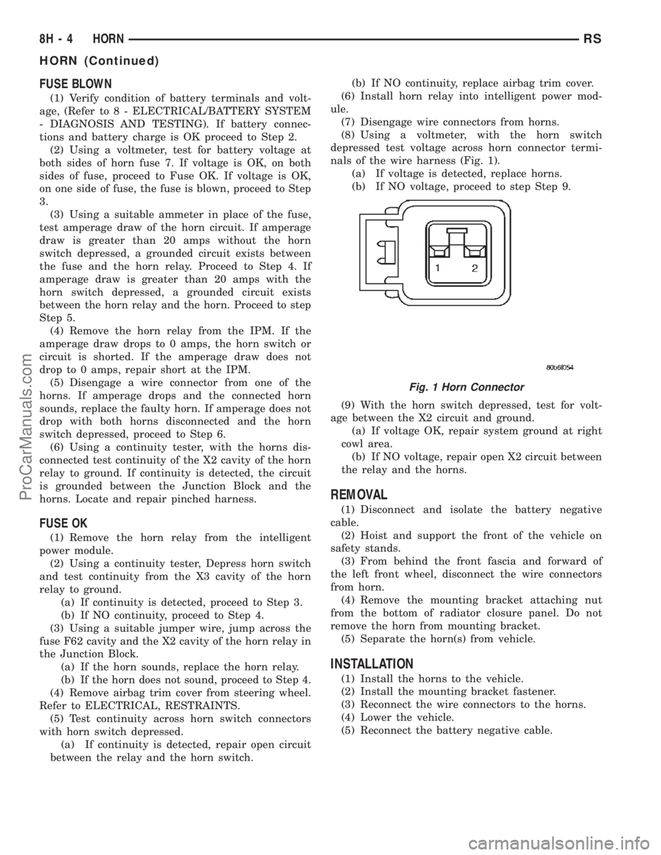
depressed test voltage across horn connector termi-
nals of the wire harness (Fig. 1).
(a) If voltage is detected, replace horns.
(b) If NO voltage, proceed to step Step 9.
(9) With the horn switch depressed, test for volt-
age between the X2 circuit and ground.
(a) If voltage OK, repair system ground at right
cowl area.
(b) If NO voltage, repair open X2 circuit between
the relay and the horns.
REMOVAL
(1) Disconnect and isolate the battery negative
cable.
(2) Hoist and support the front of the vehicle on
safety stands.
(3) From behind the front fascia and forward of
the left front wheel, disconnect the wire connectors
from horn.
(4) Remove the mounting bracket attaching nut
from the bottom of radiator closure panel. Do not
remove the horn from mounting bracket.
(5) Separate the horn(s) from vehicle.
INSTALLATION
(1) Install the horns to the vehicle.
(2) Install the mounting bracket fastener.
(3) Reconnect the wire connectors to the horns.
(4) Lower the vehicle.
(5) Reconnect the battery negative cable.
Fig. 1 Horn Connector
8H - 4 HORNRS
HORN (Continued)
ProCarManuals.com
Page 486 of 2399
IGNITION CONTROL
TABLE OF CONTENTS
page page
GLOW PLUG
DESCRIPTION..........................1
OPERATION............................1
GLOW PLUG RELAY
DESCRIPTION..........................1
OPERATION............................1CAMSHAFT POSITION SENSOR
DESCRIPTION..........................2
OPERATION............................2
REMOVAL.............................2
INSTALLATION..........................2
GLOW PLUG
DESCRIPTION
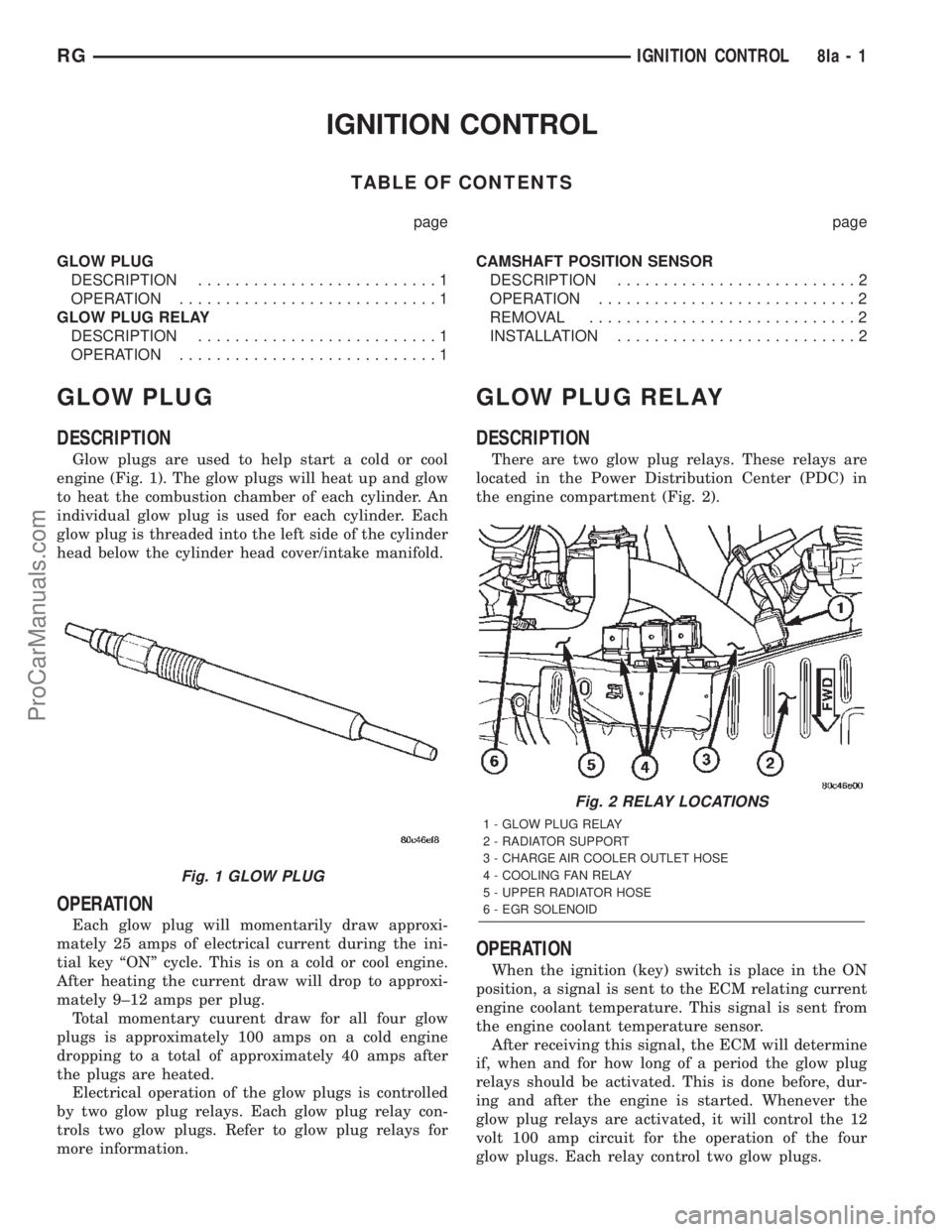
Glow plugs are used to help start a cold or cool
engine (Fig. 1). The glow plugs will heat up and glow
to heat the combustion chamber of each cylinder. An
individual glow plug is used for each cylinder. Each
glow plug is threaded into the left side of the cylinder
head below the cylinder head cover/intake manifold.
OPERATION
Each glow plug will momentarily draw approxi-
mately 25 amps of electrical current during the ini-
tial key ªONº cycle. This is on a cold or cool engine.
After heating the current draw will drop to approxi-
mately 9±12 amps per plug.
Total momentary cuurent draw for all four glow
plugs is approximately 100 amps on a cold engine
dropping to a total of approximately 40 amps after
the plugs are heated.
Electrical operation of the glow plugs is controlled
by two glow plug relays. Each glow plug relay con-
trols two glow plugs. Refer to glow plug relays for
more information.
GLOW PLUG RELAY
DESCRIPTION
There are two glow plug relays. These relays are
located in the Power Distribution Center (PDC) in
the engine compartment (Fig. 2).
OPERATION
When the ignition (key) switch is place in the ON
position, a signal is sent to the ECM relating current
engine coolant temperature. This signal is sent from
the engine coolant temperature sensor.
After receiving this signal, the ECM will determine
if, when and for how long of a period the glow plug
relays should be activated. This is done before, dur-
ing and after the engine is started. Whenever the
glow plug relays are activated, it will control the 12
volt 100 amp circuit for the operation of the four
glow plugs. Each relay control two glow plugs.
Fig. 1 GLOW PLUG
Fig. 2 RELAY LOCATIONS
1 - GLOW PLUG RELAY
2 - RADIATOR SUPPORT
3 - CHARGE AIR COOLER OUTLET HOSE
4 - COOLING FAN RELAY
5 - UPPER RADIATOR HOSE
6 - EGR SOLENOID
RGIGNITION CONTROL8Ia-1
ProCarManuals.com
Page 539 of 2399
ules push buttons located just rearward of the dis-
play screen in the overhead console. The three
universal transmitter push buttons are identified
with one, two or three light indicators so that they be
easily identified by sight or by feel.
Each of the three universal transmitter push but-
tons controls an independent radio transmitter chan-
nel. Each of these three channels can be trained to
transmit a different radio frequency signal for the
remote operation of garage door openers, motorized
gate openers, home or office lighting, security sys-
tems or just about any other device that can be
equipped with a radio receiver in the 286 to 399
MegaHertz (MHz) frequency range for remote opera-
tion. The universal transmitter is capable of operat-
ing systems using either rolling code or non-rolling
code technology.
The electronics module displays messages and a
small house-shaped icon with one, two or three dots
corresponding to the three transmitter buttons to
indicate the status of the universal transmitter. The
EVIC messages are:
²Cleared Channels- Indicates that all of the
transmitter codes stored in the universal transmitter
have been successfully cleared.
²Training- Indicates that the universal trans-
mitter is in its transmitter learning mode.
²Trained- Indicates that the universal transmit-
ter has successfully acquired a new transmitter code.
²Transmit- Indicates that a trained universal
transmitter button has been depressed and that the
universal transmitter is transmitting.
The universal transmitter cannot be repaired, and
is available for service only as a unit with the EVIC
or CMTC modules. If any of these components is
faulty or damaged, the complete EVIC or CMTC
module must be replaced.
OPERATION
The universal transmitter operates on a non-
switched source of battery current so the unit will
remain functional, regardless of the ignition switch
position. For more information on the features, pro-
gramming procedures and operation of the universal
transmitter, see the owner's manual in the vehicle
glove box.
DIAGNOSIS AND TESTING - UNIVERSAL
TRANSMITTER
If the universal transmitter is inoperative, but the
Electronic Vehicle Information Center (EVIC) or
Compass Mini-Trip Computer is operating normally,
see the owner's manual in the vehicle glove box for
instructions on training the universal transmitter.
Retrain the universal transmitter with a known good
transmitter as instructed in the owner's manual andtest the universal transmitter operation again. If the
unit is still inoperative, replace the faulty universal
transmitter and EVIC/CMTC module as a unit. If
both the universal transmitter and the EVIC/CMTC
module are inoperative, refer toOverhead Console
Diagnosis and Testingearlier in this group for fur-
ther diagnosis. For complete circuit diagrams, refer
toOverhead Consolein Wiring Diagrams.
AMBIENT TEMP SENSOR
DESCRIPTION
Ambient air temperature is monitored by the over-
head console through ambient temperature messages
received from the Front Control Module (FCM) over
the Programmable Communications Interface (PCI)
J1850 data bus circuit. The FCM receives a hard
wired input from the ambient temperature sensor.
The ambient temperature sensor is a variable resis-
tor mounted to a bracket that is secured with a screw
to the right side of the headlamp mounting module
grille opening, behind the radiator grille and in front
of the engine compartment.
Refer toFront Control Modulein Electronic
Control Modules. For complete circuit diagrams, refer
to the appropriate wiring information. The ambient
temperature sensor cannot be adjusted or repaired
and, if faulty or damaged, it must be replaced.
OPERATION
The ambient temperature sensor is a variable
resistor that operates on a five-volt reference signal
sent to it by the Front Control Module. The resis-
tance in the sensor changes as temperature changes,
changing the temperature sensor signal circuit volt-
age to the Front Control Module. Based upon the
resistance in the sensor, the Front Control Module
senses a specific voltage on the temperature sensor
signal circuit, which it is programmed to correspond
to a specific temperature. The Front Control Module
then sends the proper ambient temperature mes-
sages to the EVIC, CMTC over the PCI J1850 data
bus.
The thermometer function is supported by the
ambient temperature sensor, a wiring circuit, the
Front Control Module, the Programmable Communi-
cations Interface (PCI) data bus, and a portion of the
Electronics module. If any portion of the ambient
temperature sensor circuit fails, the Front Control
Module will self-diagnose the circuit.
The ambient temperature sensor circuit can also be
diagnosed by referring toDiagnosis and Testing -
Ambient Temperature Sensor, and Diagnosis
and Testing - Ambient Temperature Sensor Cir-
cuit. If the temperature sensor and circuit are con-
8M - 10 MESSAGE SYSTEMSRS
UNIVERSAL TRANSMITTER (Continued)
ProCarManuals.com