differential CHRYSLER CARAVAN 2002 Manual Online
[x] Cancel search | Manufacturer: CHRYSLER, Model Year: 2002, Model line: CARAVAN, Model: CHRYSLER CARAVAN 2002Pages: 2399, PDF Size: 57.96 MB
Page 1799 of 2399
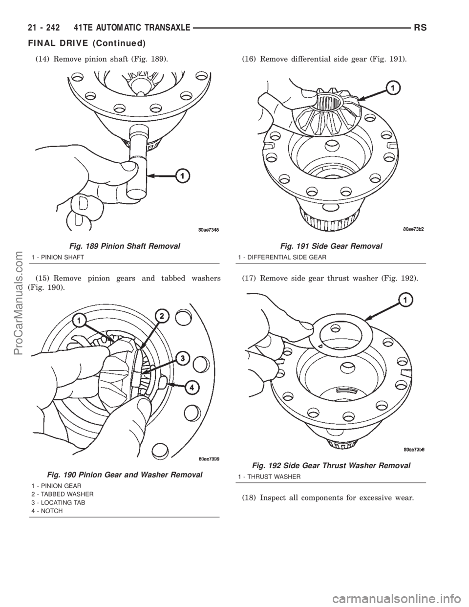
(14) Remove pinion shaft (Fig. 189).
(15) Remove pinion gears and tabbed washers
(Fig. 190).(16) Remove differential side gear (Fig. 191).
(17) Remove side gear thrust washer (Fig. 192).
(18) Inspect all components for excessive wear.
Fig. 189 Pinion Shaft Removal
1 - PINION SHAFT
Fig. 190 Pinion Gear and Washer Removal
1 - PINION GEAR
2 - TABBED WASHER
3 - LOCATING TAB
4 - NOTCH
Fig. 191 Side Gear Removal
1 - DIFFERENTIAL SIDE GEAR
Fig. 192 Side Gear Thrust Washer Removal
1 - THRUST WASHER
21 - 242 41TE AUTOMATIC TRANSAXLERS
FINAL DRIVE (Continued)
ProCarManuals.com
Page 1800 of 2399
ASSEMBLY
NOTE: The differential is serviced as an assembly.
Differential service is limited to bearing cups and
cones. Any other differential component failure
must be remedied by differential assembly and
transfer shaft replacement.
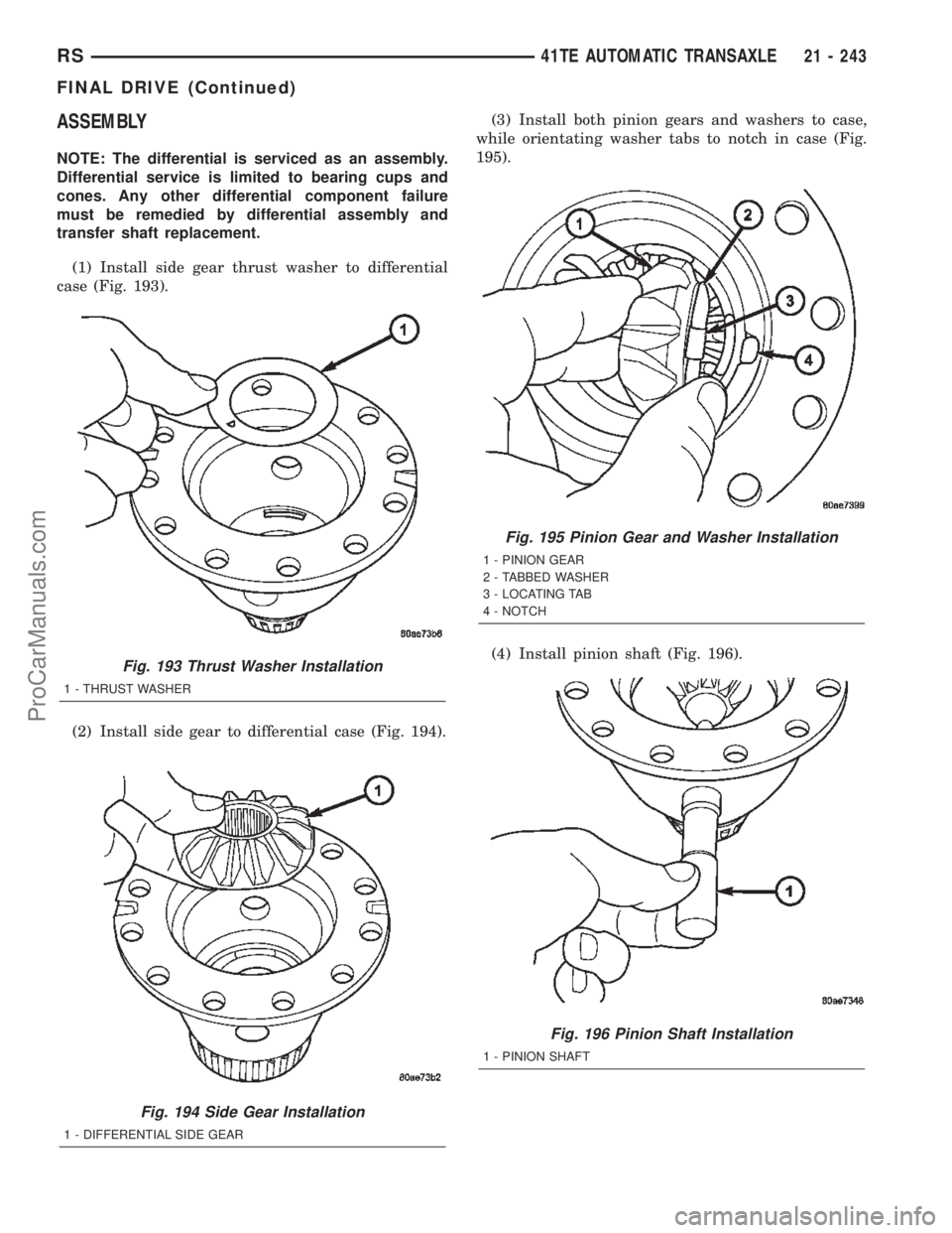
(1) Install side gear thrust washer to differential
case (Fig. 193).
(2) Install side gear to differential case (Fig. 194).(3) Install both pinion gears and washers to case,
while orientating washer tabs to notch in case (Fig.
195).
(4) Install pinion shaft (Fig. 196).
Fig. 193 Thrust Washer Installation
1 - THRUST WASHER
Fig. 194 Side Gear Installation
1 - DIFFERENTIAL SIDE GEAR
Fig. 195 Pinion Gear and Washer Installation
1 - PINION GEAR
2 - TABBED WASHER
3 - LOCATING TAB
4 - NOTCH
Fig. 196 Pinion Shaft Installation
1 - PINION SHAFT
RS41TE AUTOMATIC TRANSAXLE21 - 243
FINAL DRIVE (Continued)
ProCarManuals.com
Page 1801 of 2399
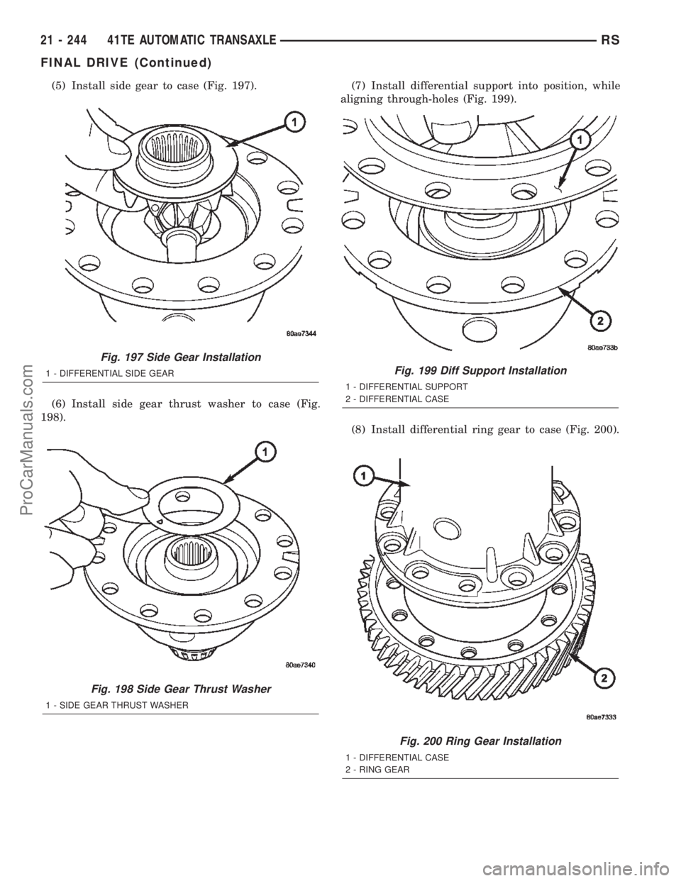
(5) Install side gear to case (Fig. 197).
(6) Install side gear thrust washer to case (Fig.
198).(7) Install differential support into position, while
aligning through-holes (Fig. 199).
(8) Install differential ring gear to case (Fig. 200).
Fig. 197 Side Gear Installation
1 - DIFFERENTIAL SIDE GEAR
Fig. 198 Side Gear Thrust Washer
1 - SIDE GEAR THRUST WASHER
Fig. 199 Diff Support Installation
1 - DIFFERENTIAL SUPPORT
2 - DIFFERENTIAL CASE
Fig. 200 Ring Gear Installation
1 - DIFFERENTIAL CASE
2 - RING GEAR
21 - 244 41TE AUTOMATIC TRANSAXLERS
FINAL DRIVE (Continued)
ProCarManuals.com
Page 1802 of 2399
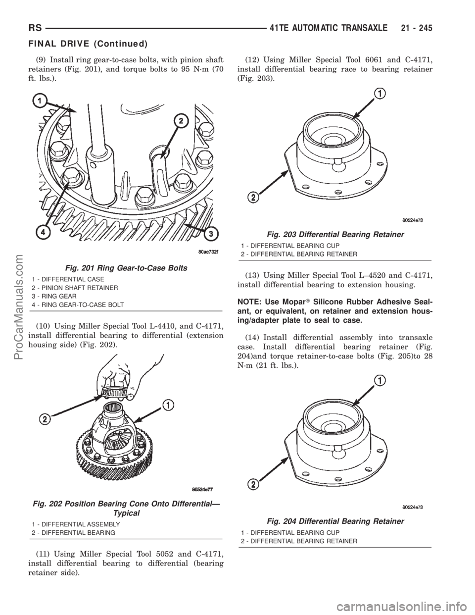
(9) Install ring gear-to-case bolts, with pinion shaft
retainers (Fig. 201), and torque bolts to 95 N´m (70
ft. lbs.).
(10) Using Miller Special Tool L-4410, and C-4171,
install differential bearing to differential (extension
housing side) (Fig. 202).
(11) Using Miller Special Tool 5052 and C-4171,
install differential bearing to differential (bearing
retainer side).(12) Using Miller Special Tool 6061 and C-4171,
install differential bearing race to bearing retainer
(Fig. 203).
(13) Using Miller Special Tool L±4520 and C-4171,
install differential bearing to extension housing.
NOTE: Use MoparTSilicone Rubber Adhesive Seal-
ant, or equivalent, on retainer and extension hous-
ing/adapter plate to seal to case.
(14) Install differential assembly into transaxle
case. Install differential bearing retainer (Fig.
204)and torque retainer-to-case bolts (Fig. 205)to 28
N´m (21 ft. lbs.).
Fig. 201 Ring Gear-to-Case Bolts
1 - DIFFERENTIAL CASE
2 - PINION SHAFT RETAINER
3 - RING GEAR
4 - RING GEAR-TO-CASE BOLT
Fig. 202 Position Bearing Cone Onto DifferentialÐ
Typical
1 - DIFFERENTIAL ASSEMBLY
2 - DIFFERENTIAL BEARING
Fig. 203 Differential Bearing Retainer
1 - DIFFERENTIAL BEARING CUP
2 - DIFFERENTIAL BEARING RETAINER
Fig. 204 Differential Bearing Retainer
1 - DIFFERENTIAL BEARING CUP
2 - DIFFERENTIAL BEARING RETAINER
RS41TE AUTOMATIC TRANSAXLE21 - 245
FINAL DRIVE (Continued)
ProCarManuals.com
Page 1803 of 2399
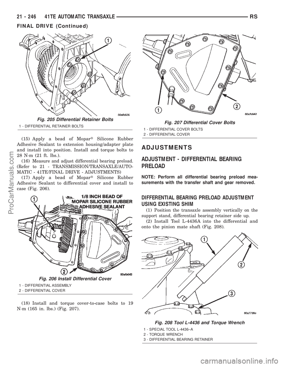
(15) Apply a bead of MopartSilicone Rubber
Adhesive Sealant to extension housing/adapter plate
and install into position. Install and torque bolts to
28 N´m (21 ft. lbs.).
(16)
Measure and adjust differential bearing preload.
(Refer to 21 - TRANSMISSION/TRANSAXLE/AUTO-
MATIC - 41TE/FINAL DRIVE - ADJUSTMENTS)
(17) Apply a bead of MopartSilicone Rubber
Adhesive Sealant to differential cover and install to
case (Fig. 206).
(18) Install and torque cover-to-case bolts to 19
N´m (165 in. lbs.) (Fig. 207).
ADJUSTMENTS
ADJUSTMENT - DIFFERENTIAL BEARING
PRELOAD
NOTE: Perform all differential bearing preload mea-
surements with the transfer shaft and gear removed.
DIFFERENTIAL BEARING PRELOAD ADJUSTMENT
USING EXISTING SHIM
(1)Position the transaxle assembly vertically on the
support stand, differential bearing retainer side up.
(2) Install Tool L-4436A into the differential and
onto the pinion mate shaft (Fig. 208).
Fig. 205 Differential Retainer Bolts
1 - DIFFERENTIAL RETAINER BOLTS
Fig. 206 Install Differential Cover
1 - DIFFERENTIAL ASSEMBLY
2 - DIFFERENTIAL COVER
Fig. 207 Differential Cover Bolts
1 - DIFFERENTIAL COVER BOLTS
2 - DIFFERENTIAL COVER
Fig. 208 Tool L-4436 and Torque Wrench
1 - SPECIAL TOOL L-4436±A
2 - TORQUE WRENCH
3 - DIFFERENTIAL BEARING RETAINER
21 - 246 41TE AUTOMATIC TRANSAXLERS
FINAL DRIVE (Continued)
ProCarManuals.com
Page 1804 of 2399
(3) Rotate the differential at least one full revolu-
tion to ensure the tapered roller bearings are fully
seated.
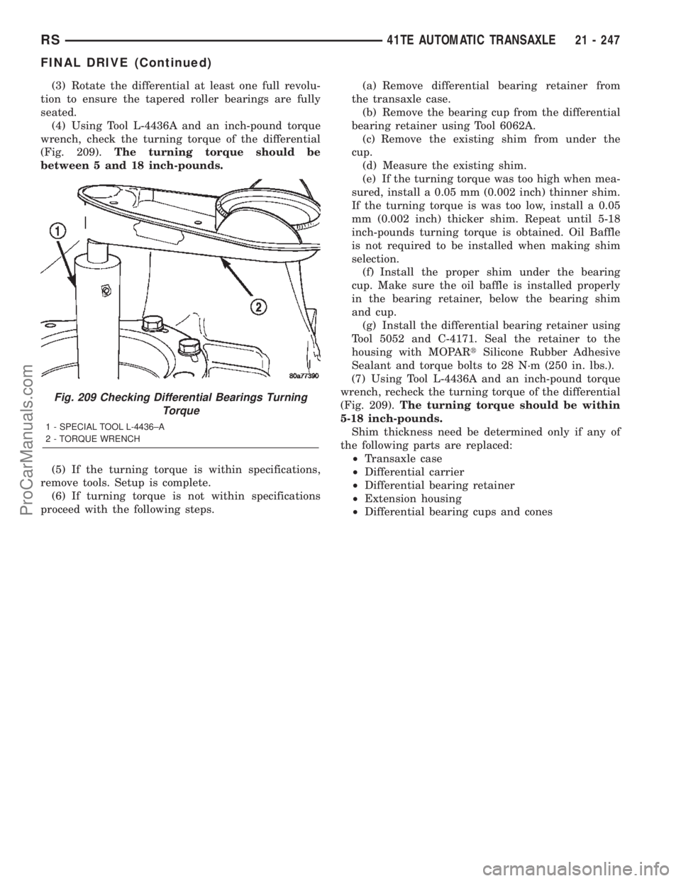
(4) Using Tool L-4436A and an inch-pound torque
wrench, check the turning torque of the differential
(Fig. 209).The turning torque should be
between 5 and 18 inch-pounds.
(5) If the turning torque is within specifications,
remove tools. Setup is complete.
(6) If turning torque is not within specifications
proceed with the following steps.(a) Remove differential bearing retainer from
the transaxle case.
(b) Remove the bearing cup from the differential
bearing retainer using Tool 6062A.
(c) Remove the existing shim from under the
cup.
(d) Measure the existing shim.
(e) If the turning torque was too high when mea-
sured, install a 0.05 mm (0.002 inch) thinner shim.
If the turning torque is was too low, install a 0.05
mm (0.002 inch) thicker shim. Repeat until 5-18
inch-pounds turning torque is obtained. Oil Baffle
is not required to be installed when making shim
selection.
(f) Install the proper shim under the bearing
cup. Make sure the oil baffle is installed properly
in the bearing retainer, below the bearing shim
and cup.
(g) Install the differential bearing retainer using
Tool 5052 and C-4171. Seal the retainer to the
housing with MOPARtSilicone Rubber Adhesive
Sealant and torque bolts to 28 N´m (250 in. lbs.).
(7) Using Tool L-4436A and an inch-pound torque
wrench, recheck the turning torque of the differential
(Fig. 209).The turning torque should be within
5-18 inch-pounds.
Shim thickness need be determined only if any of
the following parts are replaced:
²Transaxle case
²Differential carrier
²Differential bearing retainer
²Extension housing
²Differential bearing cups and cones
Fig. 209 Checking Differential Bearings Turning
Torque
1 - SPECIAL TOOL L-4436±A
2 - TORQUE WRENCH
RS41TE AUTOMATIC TRANSAXLE21 - 247
FINAL DRIVE (Continued)
ProCarManuals.com
Page 1805 of 2399
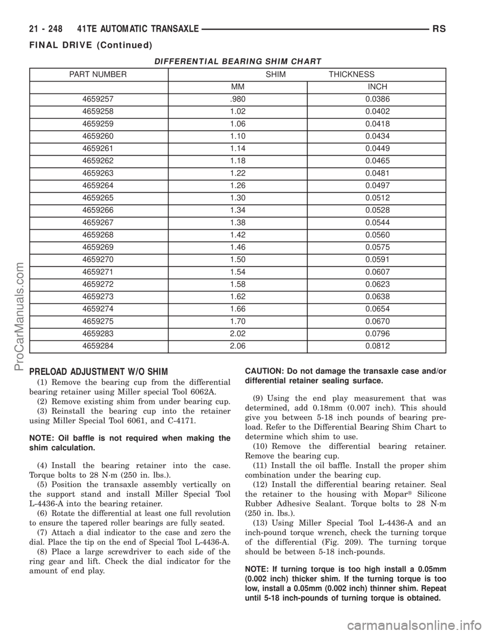
DIFFERENTIAL BEARING SHIM CHART
PART NUMBER SHIM THICKNESS
MM INCH
4659257 .980 0.0386
4659258 1.02 0.0402
4659259 1.06 0.0418
4659260 1.10 0.0434
4659261 1.14 0.0449
4659262 1.18 0.0465
4659263 1.22 0.0481
4659264 1.26 0.0497
4659265 1.30 0.0512
4659266 1.34 0.0528
4659267 1.38 0.0544
4659268 1.42 0.0560
4659269 1.46 0.0575
4659270 1.50 0.0591
4659271 1.54 0.0607
4659272 1.58 0.0623
4659273 1.62 0.0638
4659274 1.66 0.0654
4659275 1.70 0.0670
4659283 2.02 0.0796
4659284 2.06 0.0812
PRELOAD ADJUSTMENT W/O SHIM
(1) Remove the bearing cup from the differential
bearing retainer using Miller special Tool 6062A.
(2) Remove existing shim from under bearing cup.
(3) Reinstall the bearing cup into the retainer
using Miller Special Tool 6061, and C-4171.
NOTE: Oil baffle is not required when making the
shim calculation.
(4) Install the bearing retainer into the case.
Torque bolts to 28 N´m (250 in. lbs.).
(5) Position the transaxle assembly vertically on
the support stand and install Miller Special Tool
L-4436-A into the bearing retainer.
(6)
Rotate the differential at least one full revolution
to ensure the tapered roller bearings are fully seated.
(7)Attach a dial indicator to the case and zero the
dial. Place the tip on the end of Special Tool L-4436-A.
(8) Place a large screwdriver to each side of the
ring gear and lift. Check the dial indicator for the
amount of end play.CAUTION: Do not damage the transaxle case and/or
differential retainer sealing surface.
(9) Using the end play measurement that was
determined, add 0.18mm (0.007 inch). This should
give you between 5-18 inch pounds of bearing pre-
load. Refer to the Differential Bearing Shim Chart to
determine which shim to use.
(10) Remove the differential bearing retainer.
Remove the bearing cup.
(11) Install the oil baffle. Install the proper shim
combination under the bearing cup.
(12) Install the differential bearing retainer. Seal
the retainer to the housing with MopartSilicone
Rubber Adhesive Sealant. Torque bolts to 28 N´m
(250 in. lbs.).
(13) Using Miller Special Tool L-4436-A and an
inch-pound torque wrench, check the turning torque
of the differential (Fig. 209). The turning torque
should be between 5-18 inch-pounds.
NOTE: If turning torque is too high install a 0.05mm
(0.002 inch) thicker shim. If the turning torque is too
low, install a 0.05mm (0.002 inch) thinner shim. Repeat
until 5-18 inch-pounds of turning torque is obtained.
21 - 248 41TE AUTOMATIC TRANSAXLERS
FINAL DRIVE (Continued)
ProCarManuals.com
Page 1865 of 2399
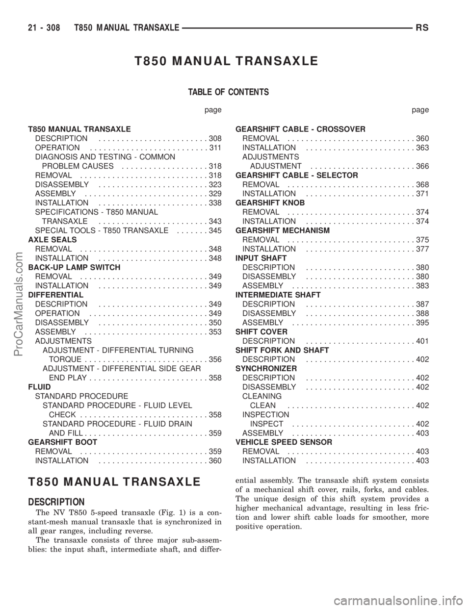
T850 MANUAL TRANSAXLE
TABLE OF CONTENTS
page page
T850 MANUAL TRANSAXLE
DESCRIPTION........................308
OPERATION..........................311
DIAGNOSIS AND TESTING - COMMON
PROBLEM CAUSES...................318
REMOVAL............................318
DISASSEMBLY........................323
ASSEMBLY...........................329
INSTALLATION........................338
SPECIFICATIONS - T850 MANUAL
TRANSAXLE........................343
SPECIAL TOOLS - T850 TRANSAXLE.......345
AXLE SEALS
REMOVAL............................348
INSTALLATION........................348
BACK-UP LAMP SWITCH
REMOVAL............................349
INSTALLATION........................349
DIFFERENTIAL
DESCRIPTION........................349
OPERATION..........................349
DISASSEMBLY........................350
ASSEMBLY...........................353
ADJUSTMENTS
ADJUSTMENT - DIFFERENTIAL TURNING
TORQUE...........................356
ADJUSTMENT - DIFFERENTIAL SIDE GEAR
ENDPLAY..........................358
FLUID
STANDARD PROCEDURE
STANDARD PROCEDURE - FLUID LEVEL
CHECK............................358
STANDARD PROCEDURE - FLUID DRAIN
AND FILL...........................359
GEARSHIFT BOOT
REMOVAL............................359
INSTALLATION........................360GEARSHIFT CABLE - CROSSOVER
REMOVAL............................360
INSTALLATION........................363
ADJUSTMENTS
ADJUSTMENT.......................366
GEARSHIFT CABLE - SELECTOR
REMOVAL............................368
INSTALLATION........................371
GEARSHIFT KNOB
REMOVAL............................374
INSTALLATION........................374
GEARSHIFT MECHANISM
REMOVAL............................375
INSTALLATION........................377
INPUT SHAFT
DESCRIPTION........................380
DISASSEMBLY........................380
ASSEMBLY...........................383
INTERMEDIATE SHAFT
DESCRIPTION........................387
DISASSEMBLY........................388
ASSEMBLY...........................395
SHIFT COVER
DESCRIPTION........................401
SHIFT FORK AND SHAFT
DESCRIPTION........................402
SYNCHRONIZER
DESCRIPTION........................402
DISASSEMBLY........................402
CLEANING
CLEAN............................402
INSPECTION
INSPECT...........................402
ASSEMBLY...........................403
VEHICLE SPEED SENSOR
REMOVAL............................403
INSTALLATION........................403
T850 MANUAL TRANSAXLE
DESCRIPTION
The NV T850 5-speed transaxle (Fig. 1) is a con-
stant-mesh manual transaxle that is synchronized in
all gear ranges, including reverse.
The transaxle consists of three major sub-assem-
blies: the input shaft, intermediate shaft, and differ-ential assembly. The transaxle shift system consists
of a mechanical shift cover, rails, forks, and cables.
The unique design of this shift system provides a
higher mechanical advantage, resulting in less fric-
tion and lower shift cable loads for smoother, more
positive operation.
21 - 308 T850 MANUAL TRANSAXLERS
ProCarManuals.com
Page 1866 of 2399
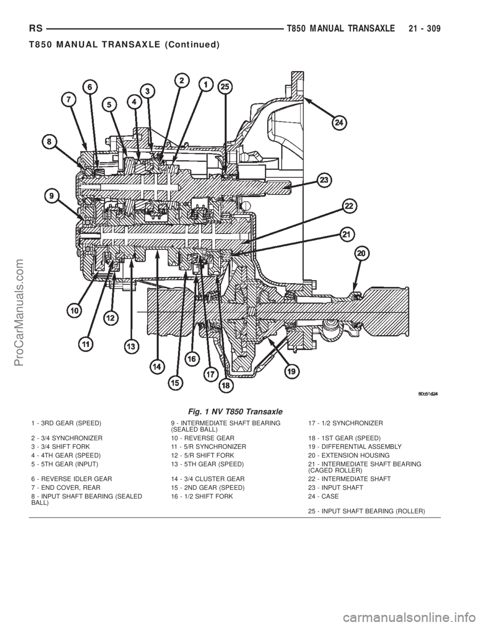
Fig. 1 NV T850 Transaxle
1 - 3RD GEAR (SPEED) 9 - INTERMEDIATE SHAFT BEARING
(SEALED BALL)17 - 1/2 SYNCHRONIZER
2 - 3/4 SYNCHRONIZER 10 - REVERSE GEAR 18 - 1ST GEAR (SPEED)
3 - 3/4 SHIFT FORK 11 - 5/R SYNCHRONIZER 19 - DIFFERENTIAL ASSEMBLY
4 - 4TH GEAR (SPEED) 12 - 5/R SHIFT FORK 20 - EXTENSION HOUSING
5 - 5TH GEAR (INPUT) 13 - 5TH GEAR (SPEED) 21 - INTERMEDIATE SHAFT BEARING
(CAGED ROLLER)
6 - REVERSE IDLER GEAR 14 - 3/4 CLUSTER GEAR 22 - INTERMEDIATE SHAFT
7 - END COVER, REAR 15 - 2ND GEAR (SPEED) 23 - INPUT SHAFT
8 - INPUT SHAFT BEARING (SEALED
BALL)16 - 1/2 SHIFT FORK 24 - CASE
25 - INPUT SHAFT BEARING (ROLLER)
RST850 MANUAL TRANSAXLE21 - 309
T850 MANUAL TRANSAXLE (Continued)
ProCarManuals.com
Page 1868 of 2399
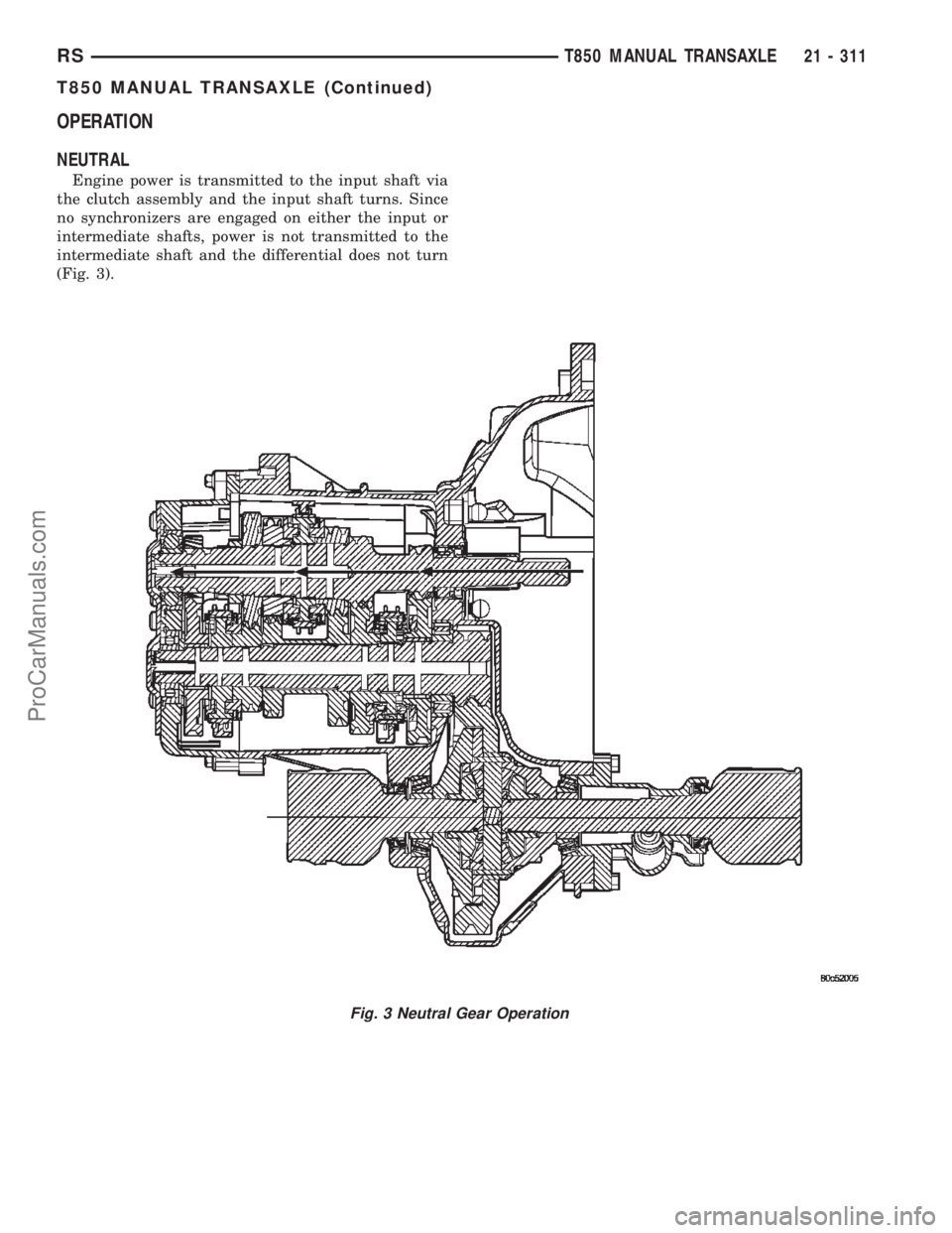
OPERATION
NEUTRAL
Engine power is transmitted to the input shaft via
the clutch assembly and the input shaft turns. Since
no synchronizers are engaged on either the input or
intermediate shafts, power is not transmitted to the
intermediate shaft and the differential does not turn
(Fig. 3).
Fig. 3 Neutral Gear Operation
RST850 MANUAL TRANSAXLE21 - 311
T850 MANUAL TRANSAXLE (Continued)
ProCarManuals.com