tow CHRYSLER CARAVAN 2003 Service Manual
[x] Cancel search | Manufacturer: CHRYSLER, Model Year: 2003, Model line: CARAVAN, Model: CHRYSLER CARAVAN 2003Pages: 2177, PDF Size: 59.81 MB
Page 1473 of 2177
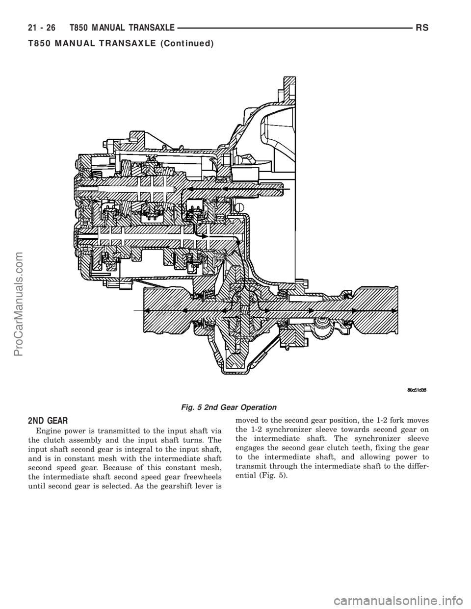
2ND GEAR
Engine power is transmitted to the input shaft via
the clutch assembly and the input shaft turns. The
input shaft second gear is integral to the input shaft,
and is in constant mesh with the intermediate shaft
second speed gear. Because of this constant mesh,
the intermediate shaft second speed gear freewheels
until second gear is selected. As the gearshift lever ismoved to the second gear position, the 1-2 fork moves
the 1-2 synchronizer sleeve towards second gear on
the intermediate shaft. The synchronizer sleeve
engages the second gear clutch teeth, fixing the gear
to the intermediate shaft, and allowing power to
transmit through the intermediate shaft to the differ-
ential (Fig. 5).
Fig. 5 2nd Gear Operation
21 - 26 T850 MANUAL TRANSAXLERS
T850 MANUAL TRANSAXLE (Continued)
ProCarManuals.com
Page 1474 of 2177
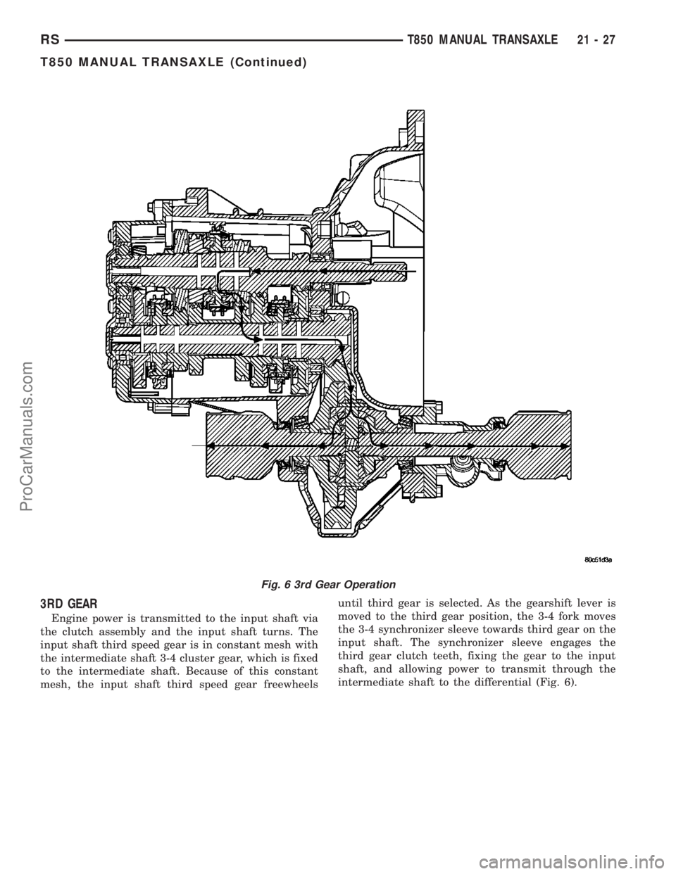
3RD GEAR
Engine power is transmitted to the input shaft via
the clutch assembly and the input shaft turns. The
input shaft third speed gear is in constant mesh with
the intermediate shaft 3-4 cluster gear, which is fixed
to the intermediate shaft. Because of this constant
mesh, the input shaft third speed gear freewheelsuntil third gear is selected. As the gearshift lever is
moved to the third gear position, the 3-4 fork moves
the 3-4 synchronizer sleeve towards third gear on the
input shaft. The synchronizer sleeve engages the
third gear clutch teeth, fixing the gear to the input
shaft, and allowing power to transmit through the
intermediate shaft to the differential (Fig. 6).
Fig. 6 3rd Gear Operation
RST850 MANUAL TRANSAXLE21-27
T850 MANUAL TRANSAXLE (Continued)
ProCarManuals.com
Page 1475 of 2177
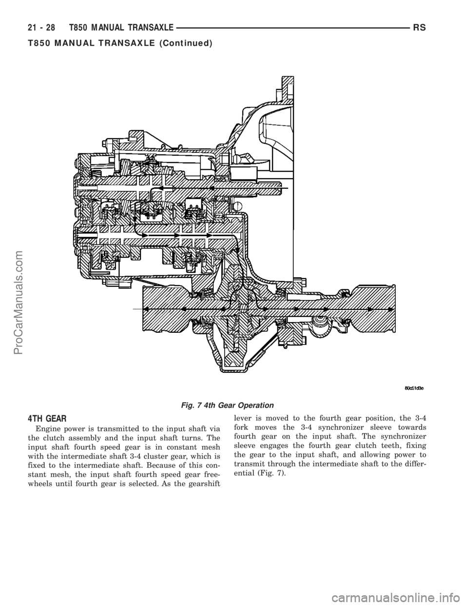
4TH GEAR
Engine power is transmitted to the input shaft via
the clutch assembly and the input shaft turns. The
input shaft fourth speed gear is in constant mesh
with the intermediate shaft 3-4 cluster gear, which is
fixed to the intermediate shaft. Because of this con-
stant mesh, the input shaft fourth speed gear free-
wheels until fourth gear is selected. As the gearshiftlever is moved to the fourth gear position, the 3-4
fork moves the 3-4 synchronizer sleeve towards
fourth gear on the input shaft. The synchronizer
sleeve engages the fourth gear clutch teeth, fixing
the gear to the input shaft, and allowing power to
transmit through the intermediate shaft to the differ-
ential (Fig. 7).
Fig. 7 4th Gear Operation
21 - 28 T850 MANUAL TRANSAXLERS
T850 MANUAL TRANSAXLE (Continued)
ProCarManuals.com
Page 1476 of 2177
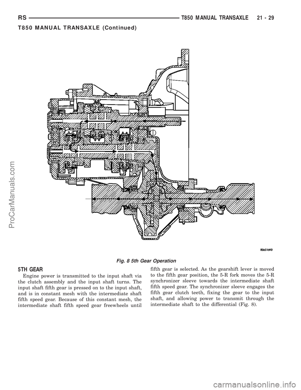
5TH GEAR
Engine power is transmitted to the input shaft via
the clutch assembly and the input shaft turns. The
input shaft fifth gear is pressed on to the input shaft,
and is in constant mesh with the intermediate shaft
fifth speed gear. Because of this constant mesh, the
intermediate shaft fifth speed gear freewheels untilfifth gear is selected. As the gearshift lever is moved
to the fifth gear position, the 5-R fork moves the 5-R
synchronizer sleeve towards the intermediate shaft
fifth speed gear. The synchronizer sleeve engages the
fifth gear clutch teeth, fixing the gear to the input
shaft, and allowing power to transmit through the
intermediate shaft to the differential (Fig. 8).
Fig. 8 5th Gear Operation
RST850 MANUAL TRANSAXLE21-29
T850 MANUAL TRANSAXLE (Continued)
ProCarManuals.com
Page 1477 of 2177
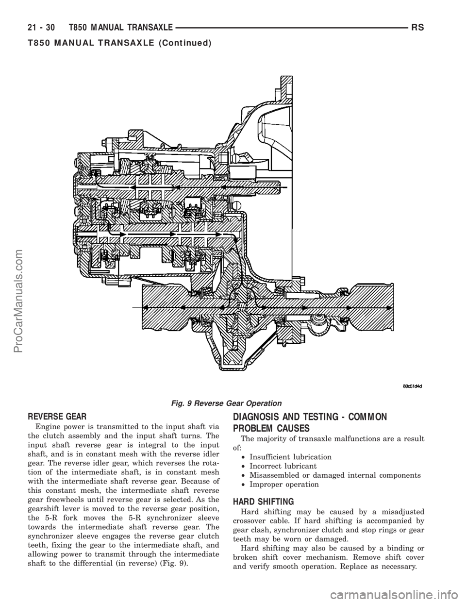
REVERSE GEAR
Engine power is transmitted to the input shaft via
the clutch assembly and the input shaft turns. The
input shaft reverse gear is integral to the input
shaft, and is in constant mesh with the reverse idler
gear. The reverse idler gear, which reverses the rota-
tion of the intermediate shaft, is in constant mesh
with the intermediate shaft reverse gear. Because of
this constant mesh, the intermediate shaft reverse
gear freewheels until reverse gear is selected. As the
gearshift lever is moved to the reverse gear position,
the 5-R fork moves the 5-R synchronizer sleeve
towards the intermediate shaft reverse gear. The
synchronizer sleeve engages the reverse gear clutch
teeth, fixing the gear to the intermediate shaft, and
allowing power to transmit through the intermediate
shaft to the differential (in reverse) (Fig. 9).
DIAGNOSIS AND TESTING - COMMON
PROBLEM CAUSES
The majority of transaxle malfunctions are a result
of:
²Insufficient lubrication
²Incorrect lubricant
²Misassembled or damaged internal components
²Improper operation
HARD SHIFTING
Hard shifting may be caused by a misadjusted
crossover cable. If hard shifting is accompanied by
gear clash, synchronizer clutch and stop rings or gear
teeth may be worn or damaged.
Hard shifting may also be caused by a binding or
broken shift cover mechanism. Remove shift cover
and verify smooth operation. Replace as necessary.
Fig. 9 Reverse Gear Operation
21 - 30 T850 MANUAL TRANSAXLERS
T850 MANUAL TRANSAXLE (Continued)
ProCarManuals.com
Page 1479 of 2177
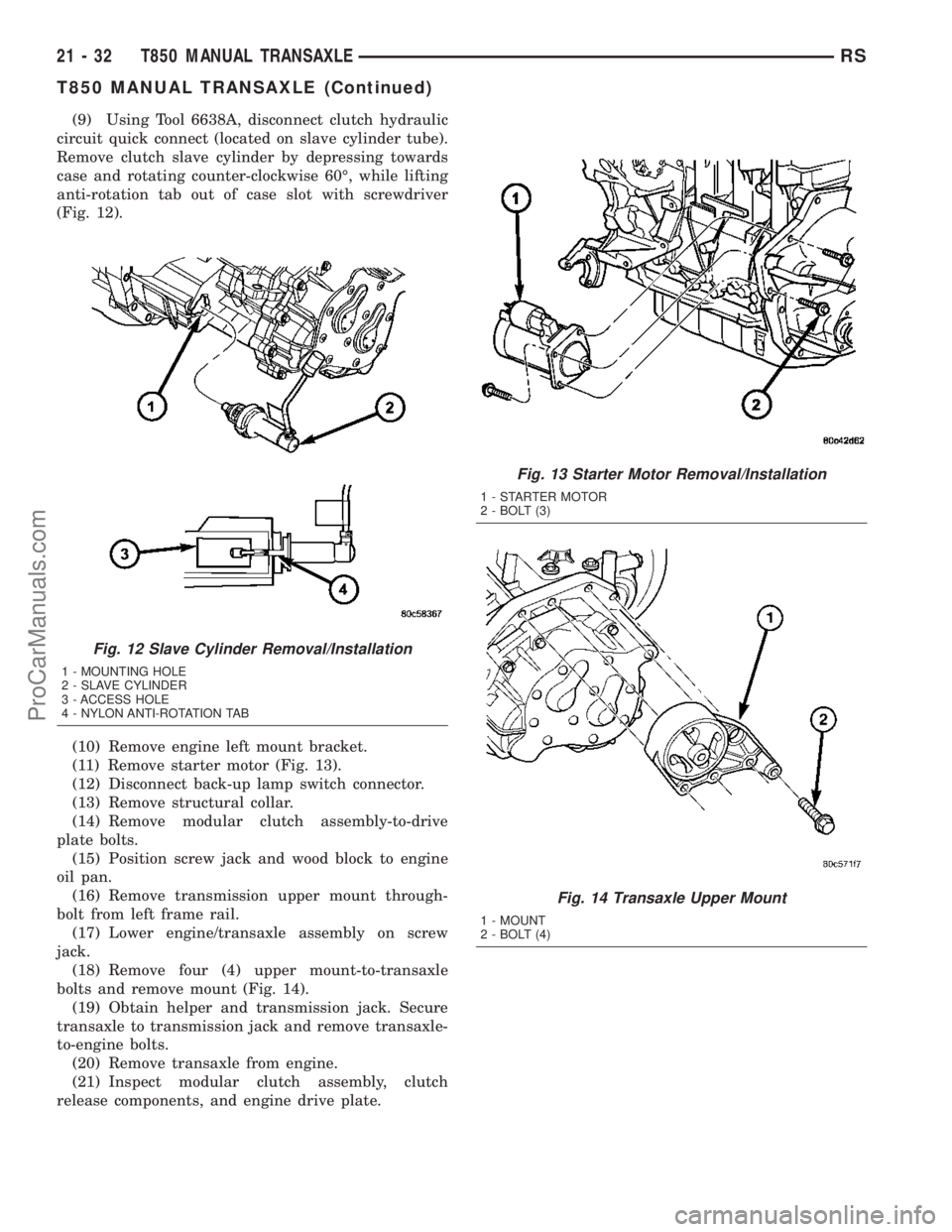
(9) Using Tool 6638A, disconnect clutch hydraulic
circuit quick connect (located on slave cylinder tube).
Remove clutch slave cylinder by depressing towards
case and rotating counter-clockwise 60É, while lifting
anti-rotation tab out of case slot with screwdriver
(Fig. 12).
(10) Remove engine left mount bracket.
(11) Remove starter motor (Fig. 13).
(12) Disconnect back-up lamp switch connector.
(13) Remove structural collar.
(14) Remove modular clutch assembly-to-drive
plate bolts.
(15) Position screw jack and wood block to engine
oil pan.
(16) Remove transmission upper mount through-
bolt from left frame rail.
(17) Lower engine/transaxle assembly on screw
jack.
(18) Remove four (4) upper mount-to-transaxle
bolts and remove mount (Fig. 14).
(19) Obtain helper and transmission jack. Secure
transaxle to transmission jack and remove transaxle-
to-engine bolts.
(20) Remove transaxle from engine.
(21) Inspect modular clutch assembly, clutch
release components, and engine drive plate.
Fig. 12 Slave Cylinder Removal/Installation
1 - MOUNTING HOLE
2 - SLAVE CYLINDER
3 - ACCESS HOLE
4 - NYLON ANTI-ROTATION TAB
Fig. 13 Starter Motor Removal/Installation
1 - STARTER MOTOR
2 - BOLT (3)
Fig. 14 Transaxle Upper Mount
1 - MOUNT
2 - BOLT (4)
21 - 32 T850 MANUAL TRANSAXLERS
T850 MANUAL TRANSAXLE (Continued)
ProCarManuals.com
Page 1481 of 2177
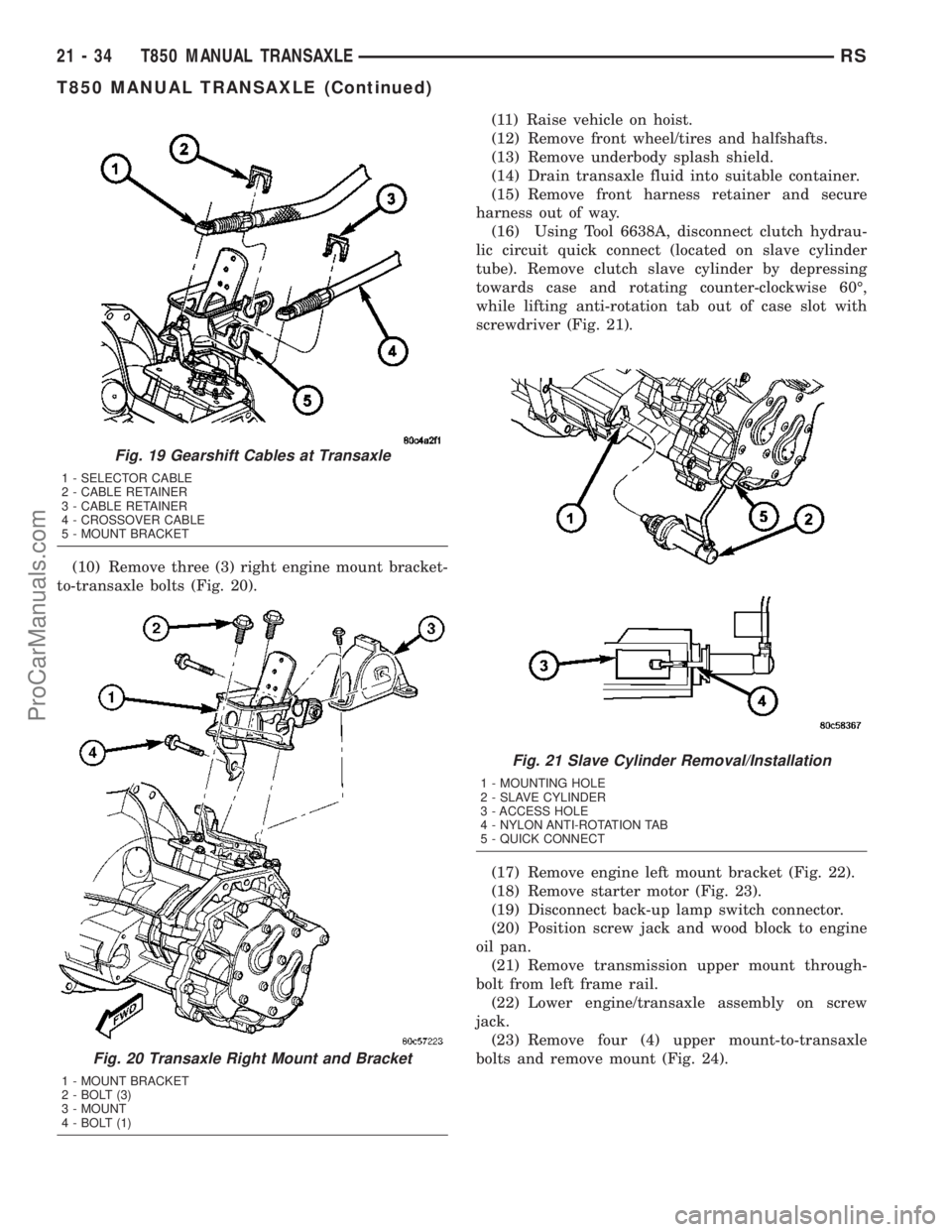
(10) Remove three (3) right engine mount bracket-
to-transaxle bolts (Fig. 20).(11) Raise vehicle on hoist.
(12) Remove front wheel/tires and halfshafts.
(13) Remove underbody splash shield.
(14) Drain transaxle fluid into suitable container.
(15) Remove front harness retainer and secure
harness out of way.
(16) Using Tool 6638A, disconnect clutch hydrau-
lic circuit quick connect (located on slave cylinder
tube). Remove clutch slave cylinder by depressing
towards case and rotating counter-clockwise 60É,
while lifting anti-rotation tab out of case slot with
screwdriver (Fig. 21).
(17) Remove engine left mount bracket (Fig. 22).
(18) Remove starter motor (Fig. 23).
(19) Disconnect back-up lamp switch connector.
(20) Position screw jack and wood block to engine
oil pan.
(21) Remove transmission upper mount through-
bolt from left frame rail.
(22) Lower engine/transaxle assembly on screw
jack.
(23) Remove four (4) upper mount-to-transaxle
bolts and remove mount (Fig. 24).
Fig. 19 Gearshift Cables at Transaxle
1 - SELECTOR CABLE
2 - CABLE RETAINER
3 - CABLE RETAINER
4 - CROSSOVER CABLE
5 - MOUNT BRACKET
Fig. 20 Transaxle Right Mount and Bracket
1 - MOUNT BRACKET
2 - BOLT (3)
3 - MOUNT
4 - BOLT (1)
Fig. 21 Slave Cylinder Removal/Installation
1 - MOUNTING HOLE
2 - SLAVE CYLINDER
3 - ACCESS HOLE
4 - NYLON ANTI-ROTATION TAB
5 - QUICK CONNECT
21 - 34 T850 MANUAL TRANSAXLERS
T850 MANUAL TRANSAXLE (Continued)
ProCarManuals.com
Page 1561 of 2177
SYNCHRONIZER
DESCRIPTION
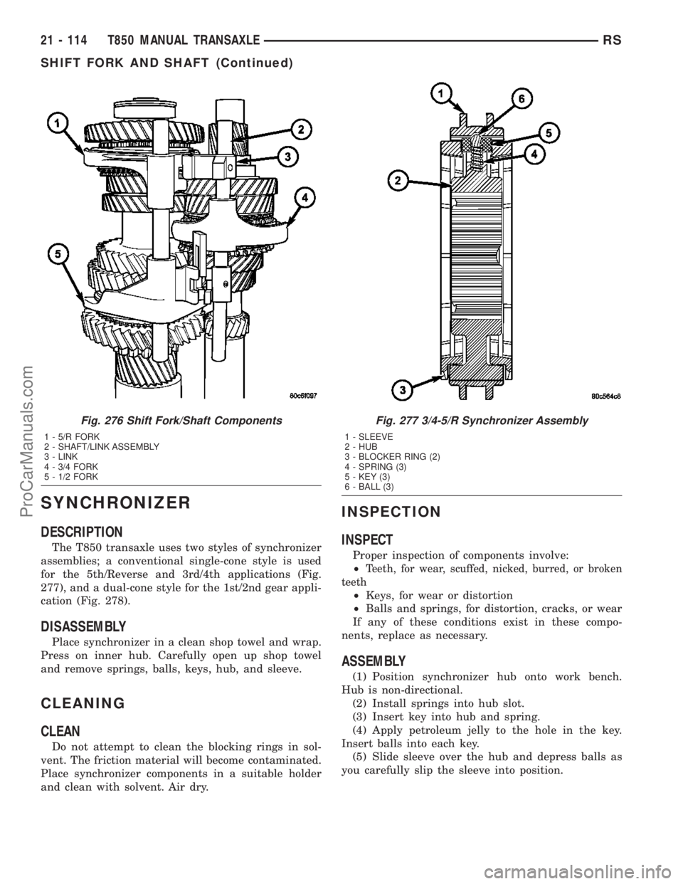
The T850 transaxle uses two styles of synchronizer
assemblies; a conventional single-cone style is used
for the 5th/Reverse and 3rd/4th applications (Fig.
277), and a dual-cone style for the 1st/2nd gear appli-
cation (Fig. 278).
DISASSEMBLY
Place synchronizer in a clean shop towel and wrap.
Press on inner hub. Carefully open up shop towel
and remove springs, balls, keys, hub, and sleeve.
CLEANING
CLEAN
Do not attempt to clean the blocking rings in sol-
vent. The friction material will become contaminated.
Place synchronizer components in a suitable holder
and clean with solvent. Air dry.
INSPECTION
INSPECT
Proper inspection of components involve:
²
Teeth, for wear, scuffed, nicked, burred, or broken
teeth
²Keys, for wear or distortion
²Balls and springs, for distortion, cracks, or wear
If any of these conditions exist in these compo-
nents, replace as necessary.
ASSEMBLY
(1) Position synchronizer hub onto work bench.
Hub is non-directional.
(2) Install springs into hub slot.
(3) Insert key into hub and spring.
(4) Apply petroleum jelly to the hole in the key.
Insert balls into each key.
(5) Slide sleeve over the hub and depress balls as
you carefully slip the sleeve into position.
Fig. 276 Shift Fork/Shaft Components
1 - 5/R FORK
2 - SHAFT/LINK ASSEMBLY
3 - LINK
4 - 3/4 FORK
5 - 1/2 FORK
Fig. 277 3/4-5/R Synchronizer Assembly
1 - SLEEVE
2 - HUB
3 - BLOCKER RING (2)
4 - SPRING (3)
5 - KEY (3)
6 - BALL (3)
21 - 114 T850 MANUAL TRANSAXLERS
SHIFT FORK AND SHAFT (Continued)
ProCarManuals.com
Page 1609 of 2177
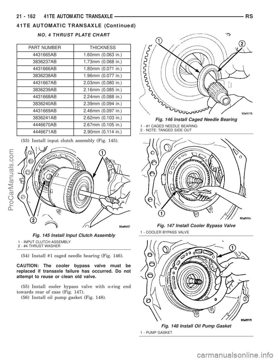
NO. 4 THRUST PLATE CHART
PART NUMBER THICKNESS
4431665AB 1.60mm (0.063 in.)
3836237AB 1.73mm (0.068 in.)
4431666AB 1.80mm (0.071 in.)
3836238AB 1.96mm (0.077 in.)
4431667AB 2.03mm (0.080 in.)
3836239AB 2.16mm (0.085 in.)
4431668AB 2.24mm (0.088 in.)
3836240AB 2.39mm (0.094 in.)
4431669AB 2.46mm (0.097 in.)
3836241AB 2.62mm (0.103 in.)
4446670AB 2.67mm (0.105 in.)
4446671AB 2.90mm (0.114 in.)
(53) Install input clutch assembly (Fig. 145).
(54) Install #1 caged needle bearing (Fig. 146).
CAUTION: The cooler bypass valve must be
replaced if transaxle failure has occurred. Do not
attempt to reuse or clean old valve.
(55) Install cooler bypass valve with o-ring end
towards rear of case (Fig. 147).
(56) Install oil pump gasket (Fig. 148).
Fig. 145 Install Input Clutch Assembly
1 - INPUT CLUTCH ASSEMBLY
2 - #4 THRUST WASHER
Fig. 146 Install Caged Needle Bearing
1 - #1 CAGED NEEDLE BEARING
2 - NOTE: TANGED SIDE OUT
Fig. 147 Install Cooler Bypass Valve
1 - COOLER BYPASS VALVE
Fig. 148 Install Oil Pump Gasket
1 - PUMP GASKET
21 - 162 41TE AUTOMATIC TRANSAXLERS
41TE AUTOMATIC TRANSAXLE (Continued)
ProCarManuals.com
Page 1671 of 2177
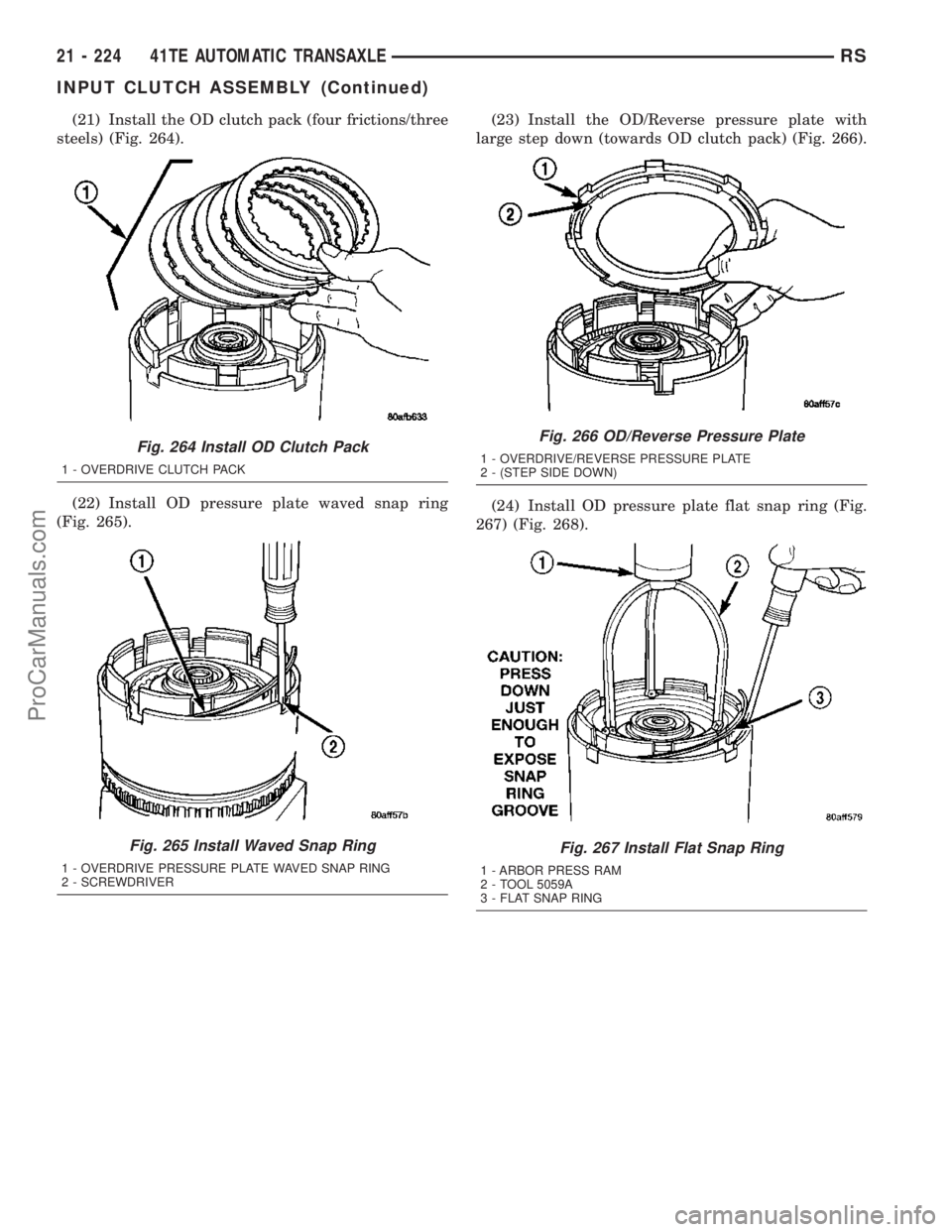
(21) Install the OD clutch pack (four frictions/three
steels) (Fig. 264).
(22) Install OD pressure plate waved snap ring
(Fig. 265).(23) Install the OD/Reverse pressure plate with
large step down (towards OD clutch pack) (Fig. 266).
(24) Install OD pressure plate flat snap ring (Fig.
267) (Fig. 268).
Fig. 264 Install OD Clutch Pack
1 - OVERDRIVE CLUTCH PACK
Fig. 265 Install Waved Snap Ring
1 - OVERDRIVE PRESSURE PLATE WAVED SNAP RING
2 - SCREWDRIVER
Fig. 266 OD/Reverse Pressure Plate
1 - OVERDRIVE/REVERSE PRESSURE PLATE
2 - (STEP SIDE DOWN)
Fig. 267 Install Flat Snap Ring
1 - ARBOR PRESS RAM
2 - TOOL 5059A
3 - FLAT SNAP RING
21 - 224 41TE AUTOMATIC TRANSAXLERS
INPUT CLUTCH ASSEMBLY (Continued)
ProCarManuals.com