light CHRYSLER CARAVAN 2003 User Guide
[x] Cancel search | Manufacturer: CHRYSLER, Model Year: 2003, Model line: CARAVAN, Model: CHRYSLER CARAVAN 2003Pages: 2177, PDF Size: 59.81 MB
Page 74 of 2177
constant speed, swerve the vehicle back and forth
from the left and to the right. This will load and
unload the bearings and change the noise level.
When bearing damage is slight, the noise is some-
times noticeable at lower speeds and at other times
is more noticeable at speeds above 105 km/h (65
mph).
REMOVAL
FRONT-WHEEL-DRIVE VEHICLES
(1) Raise vehicle. (Refer to LUBRICATION &
MAINTENANCE/HOISTING - STANDARD PROCE-
DURE)
(2) Remove wheel and tire. (Refer to 22 - TIRES/
WHEELS - REMOVAL)
(3) Remove brake drum or disc brake caliper and
rotor from hub and bearing. (Refer to 5 - BRAKES/
HYDRAULIC/MECHANICAL/DRUM - REMOVAL-
)(Refer to 5 - BRAKES/HYDRAULIC/MECHANICAL/
ROTOR - REMOVAL)
(4) If equipped with antilock brakes, perform the
following:
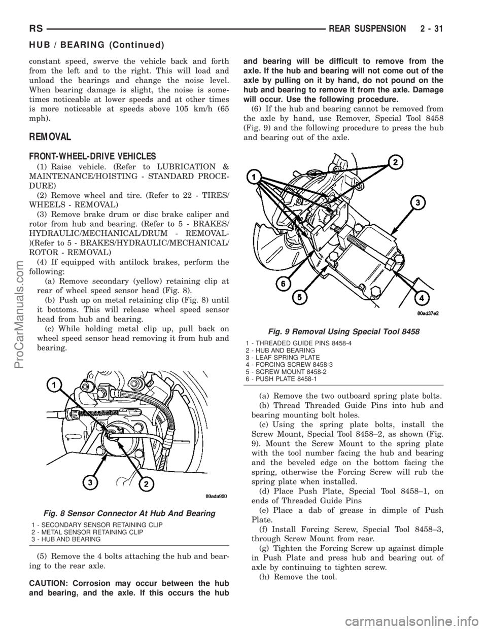
(a) Remove secondary (yellow) retaining clip at
rear of wheel speed sensor head (Fig. 8).
(b) Push up on metal retaining clip (Fig. 8) until
it bottoms. This will release wheel speed sensor
head from hub and bearing.
(c) While holding metal clip up, pull back on
wheel speed sensor head removing it from hub and
bearing.
(5) Remove the 4 bolts attaching the hub and bear-
ing to the rear axle.
CAUTION: Corrosion may occur between the hub
and bearing, and the axle. If this occurs the huband bearing will be difficult to remove from the
axle. If the hub and bearing will not come out of the
axle by pulling on it by hand, do not pound on the
hub and bearing to remove it from the axle. Damage
will occur. Use the following procedure.
(6) If the hub and bearing cannot be removed from
the axle by hand, use Remover, Special Tool 8458
(Fig. 9) and the following procedure to press the hub
and bearing out of the axle.
(a) Remove the two outboard spring plate bolts.
(b) Thread Threaded Guide Pins into hub and
bearing mounting bolt holes.
(c) Using the spring plate bolts, install the
Screw Mount, Special Tool 8458±2, as shown (Fig.
9). Mount the Screw Mount to the spring plate
with the tool number facing the hub and bearing
and the beveled edge on the bottom facing the
spring, otherwise the Forcing Screw will rub the
spring plate when installed.
(d) Place Push Plate, Special Tool 8458±1, on
ends of Threaded Guide Pins
(e) Place a dab of grease in dimple of Push
Plate.
(f) Install Forcing Screw, Special Tool 8458±3,
through Screw Mount from rear.
(g) Tighten the Forcing Screw up against dimple
in Push Plate and press hub and bearing out of
axle by continuing to tighten screw.
(h) Remove the tool.
Fig. 8 Sensor Connector At Hub And Bearing
1 - SECONDARY SENSOR RETAINING CLIP
2 - METAL SENSOR RETAINING CLIP
3 - HUB AND BEARING
Fig. 9 Removal Using Special Tool 8458
1 - THREADED GUIDE PINS 8458-4
2 - HUB AND BEARING
3 - LEAF SPRING PLATE
4 - FORCING SCREW 8458-3
5 - SCREW MOUNT 8458-2
6 - PUSH PLATE 8458-1
RSREAR SUSPENSION2-31
HUB / BEARING (Continued)
ProCarManuals.com
Page 75 of 2177
(i) Reinstall the two outboard spring plate bolts.
Tighten the bolts to 102 N´m (75 ft. lbs.) torque.
(7) Remove the hub/bearing from the rear axle and
brake support plate.
ALL-WHEEL-DRIVE VEHICLES
(1) Set the parking brake.The parking brake is
set to keep the hub and bearing, and axle shaft
from rotating when loosening the hub nut.
(2) Raise vehicle. (Refer to LUBRICATION &
MAINTENANCE/HOISTING - STANDARD PROCE-
DURE)
(3) Remove the wheel/tire assembly. (Refer to 22 -
TIRES/WHEELS - REMOVAL)
(4) Remove the cotter pin and nut retainer (Fig.
18) from the stub shaft of the outer C/V joint.
(5) Remove the spring washer (Fig. 17) from the
stub shaft of the outer C/V joint.
(6) Remove the hub nut and washer (Fig. 16) from
the stub shaft of the outer C/V joint.
(7) Remove the 6 bolts mounting the driveshaft
inner joint to the output shaft of the rear drive line
module.
(8) Remove the rear wheel speed sensor (Fig. 19)
from the rear hub/bearing.
(9) Release the parking brake.
(10) Remove the disc brake caliper to adapter
guide pin bolts (Fig. 15).
(11) Remove rear caliper from adapter using the
following procedure. First rotate front of caliper up
from the adapter. Then pull the rear of the caliper
and the outboard brake shoe anti-rattle clip out from
under the rear abutment on the adapter (Fig. 14).
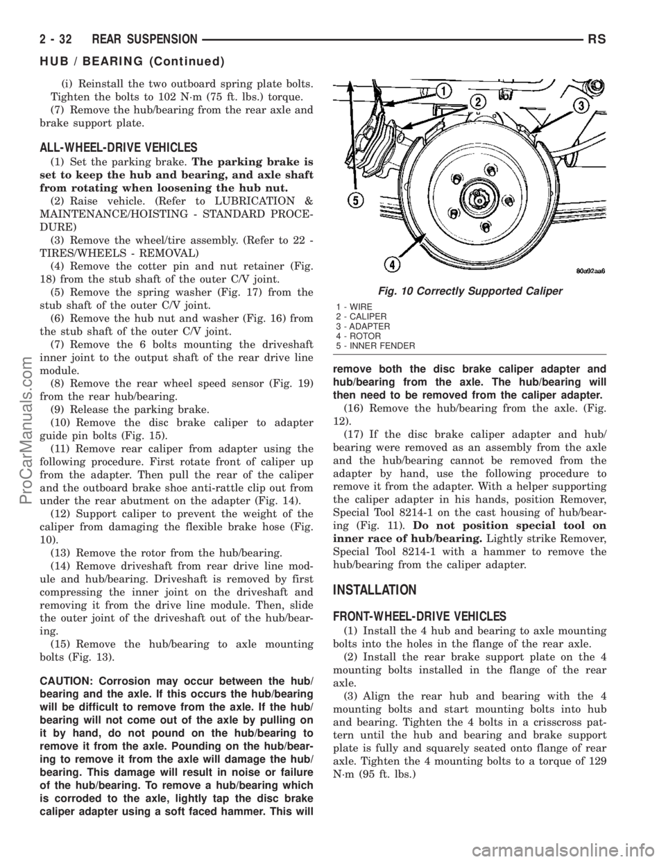
(12) Support caliper to prevent the weight of the
caliper from damaging the flexible brake hose (Fig.
10).
(13) Remove the rotor from the hub/bearing.
(14) Remove driveshaft from rear drive line mod-
ule and hub/bearing. Driveshaft is removed by first
compressing the inner joint on the driveshaft and
removing it from the drive line module. Then, slide
the outer joint of the driveshaft out of the hub/bear-
ing.
(15) Remove the hub/bearing to axle mounting
bolts (Fig. 13).
CAUTION: Corrosion may occur between the hub/
bearing and the axle. If this occurs the hub/bearing
will be difficult to remove from the axle. If the hub/
bearing will not come out of the axle by pulling on
it by hand, do not pound on the hub/bearing to
remove it from the axle. Pounding on the hub/bear-
ing to remove it from the axle will damage the hub/
bearing. This damage will result in noise or failure
of the hub/bearing. To remove a hub/bearing which
is corroded to the axle, lightly tap the disc brake
caliper adapter using a soft faced hammer. This willremove both the disc brake caliper adapter and
hub/bearing from the axle. The hub/bearing will
then need to be removed from the caliper adapter.
(16) Remove the hub/bearing from the axle. (Fig.
12).
(17) If the disc brake caliper adapter and hub/
bearing were removed as an assembly from the axle
and the hub/bearing cannot be removed from the
adapter by hand, use the following procedure to
remove it from the adapter. With a helper supporting
the caliper adapter in his hands, position Remover,
Special Tool 8214-1 on the cast housing of hub/bear-
ing (Fig. 11).Do not position special tool on
inner race of hub/bearing.Lightly strike Remover,
Special Tool 8214-1 with a hammer to remove the
hub/bearing from the caliper adapter.
INSTALLATION
FRONT-WHEEL-DRIVE VEHICLES
(1) Install the 4 hub and bearing to axle mounting
bolts into the holes in the flange of the rear axle.
(2) Install the rear brake support plate on the 4
mounting bolts installed in the flange of the rear
axle.
(3) Align the rear hub and bearing with the 4
mounting bolts and start mounting bolts into hub
and bearing. Tighten the 4 bolts in a crisscross pat-
tern until the hub and bearing and brake support
plate is fully and squarely seated onto flange of rear
axle. Tighten the 4 mounting bolts to a torque of 129
N´m (95 ft. lbs.)
Fig. 10 Correctly Supported Caliper
1 - WIRE
2 - CALIPER
3 - ADAPTER
4 - ROTOR
5 - INNER FENDER
2 - 32 REAR SUSPENSIONRS
HUB / BEARING (Continued)
ProCarManuals.com
Page 85 of 2177
SPRING MOUNTS - FRONT
REMOVAL
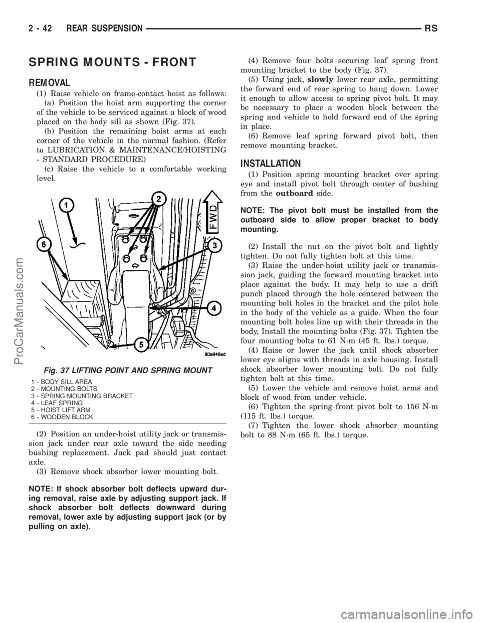
(1) Raise vehicle on frame-contact hoist as follows:
(a) Position the hoist arm supporting the corner
of the vehicle to be serviced against a block of wood
placed on the body sill as shown (Fig. 37).
(b) Position the remaining hoist arms at each
corner of the vehicle in the normal fashion. (Refer
to LUBRICATION & MAINTENANCE/HOISTING
- STANDARD PROCEDURE)
(c) Raise the vehicle to a comfortable working
level.
(2) Position an under-hoist utility jack or transmis-
sion jack under rear axle toward the side needing
bushing replacement. Jack pad should just contact
axle.
(3) Remove shock absorber lower mounting bolt.
NOTE: If shock absorber bolt deflects upward dur-
ing removal, raise axle by adjusting support jack. If
shock absorber bolt deflects downward during
removal, lower axle by adjusting support jack (or by
pulling on axle).(4) Remove four bolts securing leaf spring front
mounting bracket to the body (Fig. 37).
(5) Using jack,slowlylower rear axle, permitting
the forward end of rear spring to hang down. Lower
it enough to allow access to spring pivot bolt. It may
be necessary to place a wooden block between the
spring and vehicle to hold forward end of the spring
in place.
(6) Remove leaf spring forward pivot bolt, then
remove mounting bracket.
INSTALLATION
(1) Position spring mounting bracket over spring
eye and install pivot bolt through center of bushing
from theoutboardside.
NOTE: The pivot bolt must be installed from the
outboard side to allow proper bracket to body
mounting.
(2) Install the nut on the pivot bolt and lightly
tighten. Do not fully tighten bolt at this time.
(3) Raise the under-hoist utility jack or transmis-
sion jack, guiding the forward mounting bracket into
place against the body. It may help to use a drift
punch placed through the hole centered between the
mounting bolt holes in the bracket and the pilot hole
in the body of the vehicle as a guide. When the four
mounting bolt holes line up with their threads in the
body, Install the mounting bolts (Fig. 37). Tighten the
four mounting bolts to 61 N´m (45 ft. lbs.) torque.
(4) Raise or lower the jack until shock absorber
lower eye aligns with threads in axle housing. Install
shock absorber lower mounting bolt. Do not fully
tighten bolt at this time.
(5) Lower the vehicle and remove hoist arms and
block of wood from under vehicle.
(6) Tighten the spring front pivot bolt to 156 N´m
(115 ft. lbs.) torque.
(7) Tighten the lower shock absorber mounting
bolt to 88 N´m (65 ft. lbs.) torque.
Fig. 37 LIFTING POINT AND SPRING MOUNT
1 - BODY SILL AREA
2 - MOUNTING BOLTS
3 - SPRING MOUNTING BRACKET
4 - LEAF SPRING
5 - HOIST LIFT ARM
6 - WOODEN BLOCK
2 - 42 REAR SUSPENSIONRS
ProCarManuals.com
Page 103 of 2177
(12) Pull steering knuckle assembly down and
away from the outer C/V joint of the half shaft
assembly while pulling the joint out of the hub bear-
ing.
(13) Support the outer end of the half shaft assem-
bly. Insert a pry bar between inner tripod joint and
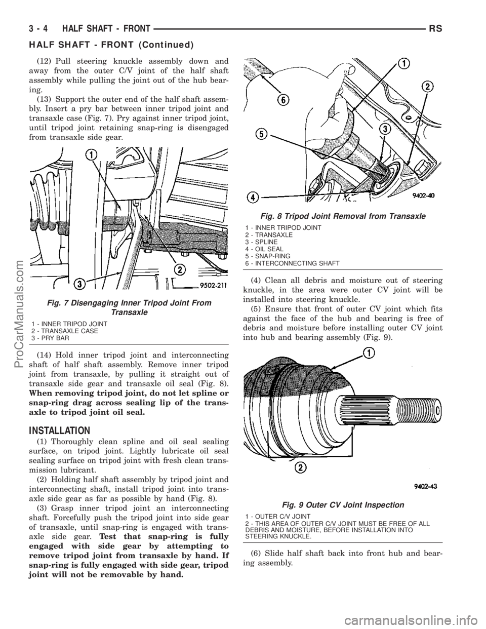
transaxle case (Fig. 7). Pry against inner tripod joint,
until tripod joint retaining snap-ring is disengaged
from transaxle side gear.
(14) Hold inner tripod joint and interconnecting
shaft of half shaft assembly. Remove inner tripod
joint from transaxle, by pulling it straight out of
transaxle side gear and transaxle oil seal (Fig. 8).
When removing tripod joint, do not let spline or
snap-ring drag across sealing lip of the trans-
axle to tripod joint oil seal.
INSTALLATION
(1) Thoroughly clean spline and oil seal sealing
surface, on tripod joint. Lightly lubricate oil seal
sealing surface on tripod joint with fresh clean trans-
mission lubricant.
(2) Holding half shaft assembly by tripod joint and
interconnecting shaft, install tripod joint into trans-
axle side gear as far as possible by hand (Fig. 8).
(3) Grasp inner tripod joint an interconnecting
shaft. Forcefully push the tripod joint into side gear
of transaxle, until snap-ring is engaged with trans-
axle side gear.Test that snap-ring is fully
engaged with side gear by attempting to
remove tripod joint from transaxle by hand. If
snap-ring is fully engaged with side gear, tripod
joint will not be removable by hand.(4) Clean all debris and moisture out of steering
knuckle, in the area were outer CV joint will be
installed into steering knuckle.
(5) Ensure that front of outer CV joint which fits
against the face of the hub and bearing is free of
debris and moisture before installing outer CV joint
into hub and bearing assembly (Fig. 9).
(6) Slide half shaft back into front hub and bear-
ing assembly.
Fig. 7 Disengaging Inner Tripod Joint From
Transaxle
1 - INNER TRIPOD JOINT
2 - TRANSAXLE CASE
3-PRYBAR
Fig. 8 Tripod Joint Removal from Transaxle
1 - INNER TRIPOD JOINT
2 - TRANSAXLE
3 - SPLINE
4 - OIL SEAL
5 - SNAP-RING
6 - INTERCONNECTING SHAFT
Fig. 9 Outer CV Joint Inspection
1 - OUTER C/V JOINT
2 - THIS AREA OF OUTER C/V JOINT MUST BE FREE OF ALL
DEBRIS AND MOISTURE, BEFORE INSTALLATION INTO
STEERING KNUCKLE.
3 - 4 HALF SHAFT - FRONTRS
HALF SHAFT - FRONT (Continued)
ProCarManuals.com
Page 113 of 2177
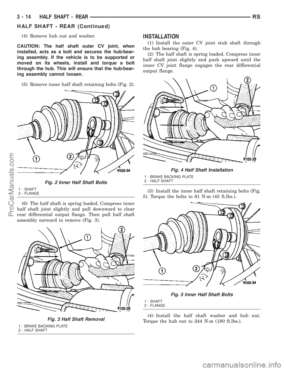
(4) Remove hub nut and washer.
CAUTION: The half shaft outer CV joint, when
installed, acts as a bolt and secures the hub/bear-
ing assembly. If the vehicle is to be supported or
moved on its wheels, install and torque a bolt
through the hub. This will ensure that the hub/bear-
ing assembly cannot loosen.
(5) Remove inner half shaft retaining bolts (Fig. 2).
(6) The half shaft is spring loaded. Compress inner
half shaft joint slightly and pull downward to clear
rear differential output flange. Then pull half shaft
assembly outward to remove (Fig. 3).INSTALLATION
(1) Install the outer CV joint stub shaft through
the hub bearing (Fig. 4).
(2) The half shaft is spring loaded. Compress inner
half shaft joint slightly and push upward until the
inner CV joint flange engages the rear differential
output flange.
(3) Install the inner half shaft retaining bolts (Fig.
5). Torque the bolts to 61 N´m (45 ft.lbs.).
(4) Install the half shaft washer and hub nut.
Torque the hub nut to 244 N´m (180 ft.lbs.).
Fig. 2 Inner Half Shaft Bolts
1 - SHAFT
2 - FLANGE
Fig. 3 Half Shaft Removal
1 - BRAKE BACKING PLATE
2 - HALF SHAFT
Fig. 4 Half Shaft Installation
1 - BRAKE BACKING PLATE
2 - HALF SHAFT
Fig. 5 Inner Half Shaft Bolts
1 - SHAFT
2 - FLANGE
3 - 14 HALF SHAFT - REARRS
HALF SHAFT - REAR (Continued)
ProCarManuals.com
Page 124 of 2177
²Engine
²Transmission
²Exhaust
²Propeller shaft (vibration)
²Vehicle body (drumming)
Driveline module noises are normally divided into
two categories: gear noise or bearing noise. A thor-
ough and careful inspection should be completed to
determine the actual source of the noise before
replacing the driveline module.
The rubber mounting bushings help to dampen-out
driveline module noise when properly installed.
Inspect to confirm that no metal contact exists
between the driveline module case and the body. The
complete isolation of noise to one area requires
expertise and experience. Identifying certain types of
vehicle noise baffles even the most capable techni-
cians. Often such practices as:
²Increase tire inflation pressure to eliminate tire
noise.
²Listen for noise at varying speeds with different
driveline load conditions
²Swerving the vehicle from left to right to detect
wheel bearing noise.
All driveline module assemblies produce noise to a
certain extent. Slight carrier noise that is noticeable
only at certain speeds or isolated situations should be
considered normal. Carrier noise tends to peak at a
variety of vehicle speeds. Noise isNOT ALWAYSan
indication of a problem within the carrier.
TIRE NOISE
Tire noise is often mistaken for driveline module
noise. Tires that are unbalanced, worn unevenly or
are worn in a saw-tooth manner are usually noisy.
They often produce a noise that appears to originate
in the driveline module.
Tire noise changes with different road surfaces, but
driveline module noise does not. Inflate all four tires
with approximately 20 psi (138 kPa) more than the
recommended inflation pressure (for test purposes
only). This will alter noise caused by tires, but will
not affect noise caused by the differential. Rear axle
noise usually ceases when coasting at speeds less
than 30 mph (48 km/h); however, tire noise contin-
ues, but at a lower frequency, as the speed is
reduced.
After test has been completed lower tire pressure
back to recommended pressure.
GEAR NOISE (DRIVE PINION AND RING GEAR)
Abnormal gear noise is rare and is usually caused
by scoring on the ring gear and drive pinion. Scoring
is the result of insufficient or incorrect lubricant in
the carrier housing.Abnormal gear noise can be easily recognized. It
produces a cycling tone that will be very pronounced
within a given speed range. The noise can occur dur-
ing one or more of the following drive conditions:
²Drive
²Road load
²Float
²Coast
Abnormal gear noise usually tends to peak within
a narrow vehicle speed range or ranges. It is usually
more pronounced between 30 to 40 mph (48 to 64
km/h) and 50 to 60 mph (80 to 96 km/h). When objec-
tionable gear noise occurs, note the driving condi-
tions and the speed range.
BEARING NOISE (DRIVE PINION AND
DIFFERENTIAL)
Defective bearings produce a rough growl that is
constant in pitch and varies with the speed of vehi-
cle. Being aware of this will enable a technician to
separate bearing noise from gear noise.
Drive pinion bearing noise that results from defec-
tive or damaged bearings can usually be identified by
its constant, rough sound. Drive pinion front bearing
is usually more pronounced during a coast condition.
Drive pinion rear bearing noise is more pronounced
during a drive condition. The drive pinion bearings
are rotating at a higher rate of speed than either the
differential side bearings or the axle shaft bearing.
Differential side bearing noise will usually produce
a constant, rough sound. The sound is much lower in
frequency than the noise caused by drive pinion bear-
ings.
Bearing noise can best be detected by road testing
the vehicle on a smooth road (black top). However, it
is easy to mistake tire noise for bearing noise. If a
doubt exists, the tire treads should be examined for
irregularities that often causes a noise that resem-
bles bearing noise.
ENGINE AND TRANSMISSION NOISE
Sometimes noise that appears to be in the driv-
eline module assembly is actually caused by the
engine or the transmission. To identify the true
source of the noise, note the approximate vehicle
speed and/or RPM when the noise is most noticeable.
Stop the vehicle next to a flat brick or cement wall
(this will help reflect the sound). Place the transaxle
inNEUTRAL. Accelerate the engine slowly up
through the engine speed that matches the vehicle
speed noted when the noise occurred. If the same
noise is produced, it usually indicates that the noise
is being caused by the engine or transaxle.
RSREAR DRIVELINE MODULE3-25
REAR DRIVELINE MODULE (Continued)
ProCarManuals.com
Page 150 of 2177
CABLES - PARKING BRAKE
REMOVAL
REMOVAL - PARKING BRAKE CABLE
(FRONT)............................59
REMOVAL - PARKING BRAKE CABLE
(INTERMEDIATE)......................60
REMOVAL - PARKING BRAKE CABLE
(RIGHT REAR)........................60
REMOVAL - PARKING BRAKE CABLE (LEFT
REAR)..............................62
INSTALLATION
INSTALLATION - PARKING BRAKE CABLE
(FRONT)............................63
INSTALLATION - PARKING BRAKE CABLE
(INTERMEDIATE)......................63
INSTALLATION - PARKING BRAKE CABLE
(RIGHT REAR)........................63
INSTALLATION - PARKING BRAKE CABLE
(LEFT REAR).........................64ADJUSTMENTS
ADJUSTMENT - PARKING BRAKE CABLES . 64
CABLES - PARKING BRAKE (EXPORT)
REMOVAL - FRONT CABLE...............64
INSTALLATION - FRONT CABLE............64
LEVER - PARKING BRAKE
REMOVAL.............................64
INSTALLATION.........................65
LEVER - PARKING BRAKE (EXPORT)
REMOVAL - PARKING BRAKE LEVER AND
FRONT CABLE.......................65
INSTALLATION - PARKING BRAKE LEVER
AND FRONT CABLE...................66
SHOES - PARKING BRAKE
REMOVAL.............................67
INSTALLATION.........................72
ADJUSTMENTS
ADJUSTMENT - PARKING BRAKE SHOES . . 73
BRAKES - BASE
DESCRIPTION
DESCRIPTION - BASE BRAKES
The base brake system consists of the following
components:
²Brake pedal
²Power brake booster
²Master cylinder
²Brake tubes and hoses
²Proportioning valve (non-ABS vehicles only)
²Disc brakes
²Drum brakes
²Brake lamp switch
²Brake fluid level switch
²Parking brakes
Front disc brakes control the braking of the front
wheels; rear braking is controlled by rear drum
brakes or rear disc brakes depending on options.
The hydraulic brake system is diagonally split on
both the non-antilock braking systems and antilock
braking systems. That means the left front and right
rear brakes are on one hydraulic circuit and the right
front and left rear are on the other.
For information on the brake lamp switch, (Refer
to 8 - ELECTRICAL/LAMPS/LIGHTING - EXTERI-
OR/BRAKE LAMP SWITCH - DESCRIPTION)Vehicles equipped with the optional antilock brake
system (ABS) use a system designated Mark 20e. It
is available with or without traction control. This
system shares most base brake hardware used on
vehicles without ABS. ABS components are described
in detail in ANTILOCK BRAKE SYSTEM.DESCRIPTION - BASE BRAKES (EXPORT)
Four-Wheel Disc Antilock Brakes are standard on
all models.
OPERATION - BASE BRAKES
When a vehicle needs to be stopped, the driver
applies the brake pedal. The brake pedal pushes the
input rod of the power brake booster into the booster.
The booster uses vacuum to ease pedal effort as force
is transferred through the booster to the master cyl-
inder. The booster's output rod pushes in the master
cylinder's primary and secondary pistons applying
hydraulic pressure through the chassis brake tubes
to the brakes at each tire and wheel assembly.
The parking brakes are foot-operated. When
applied, the parking brake lever pulls on cables that
actuate brake shoes at each rear wheel. These shoes
come in contact with a hub mounted drum (drum for
disc/drum brakes or drum-in-hat for disc/disc brakes)
and hold it in place.
RSBRAKES - BASE5-3
ProCarManuals.com
Page 152 of 2177
RED BRAKE WARNING INDICATOR LAMP
CONDITION POSSIBLE CAUSES CORRECTION
RED BRAKE WARNING
LAMP ON1. Parking brake lever not fully
released.1. Release parking brake lever.
2. Parking brake warning lamp
switch on parking brake lever.2. Inspect and replace switch as necessary.
3. Brake fluid level low in reservoir. 3. Fill reservoir. Check entire system for
leaks. Repair or replace as required.
4. Brake fluid level switch. 4. Disconnect switch wiring connector. If
lamp goes out, replace switch.
5. Mechanical instrument cluster
(MIC) problem.5. Refer to appropriate Diagnostic
information.
6. Amber ABS Warning Indicator
Lamp also illuminated.6. Refer to appropriate Diagnostic
information.
BRAKE NOISE
CONDITION POSSIBLE CAUSES CORRECTION
CLICK OR SQUAWK ON
PEDAL APPLICATION1. Brake lamp switch. 1. Replace switch.
2. Brake Transmission Shift Interlock
Linkage.2. Lubricate BTSI linkage.
3. Pedal pivot bushings 3. Lubricate pivot bushings. Replace if
necessary.
DISC BRAKE CHIRP 1. Excessive brake rotor runout. 1. Follow brake rotor diagnosis and testing.
Correct as necessary.
2. Lack of lubricant on brake caliper
slides.2. Lubricate brake caliper slides.
3. Caliper/shoes not fully seated. 3. Reseat caliper/shoes.
DISC BRAKE RATTLE OR
CLUNK1. Broken or missing anti-rattle
spring clips on shoes.1. Replace brake shoes.
2. Caliper guide pins/bolts loose. 2. Tighten guide pins/bolts.
DISC BRAKE SQUEAK AT
LOW SPEED (WHILE
APPLYING LIGHT BRAKE
PEDAL EFFORT)1. Brake shoe linings. 1. Replace brake shoes.
DRUM BRAKE CHIRP 1. Lack of lubricant on brake shoe
support plate where shoes ride.1. Lubricate shoe contact areas on brake
shoe support plates.
DRUM BRAKE CLUNK 1. Drum(s) have threaded machined
braking surface.1. Replace brake drums as necessary.
DRUM BRAKE HOWL OR
MOAN1. Lack of lubricant on brake shoe
support plate where shoes ride and
at the anchor.1. Lubricate shoe contact areas on brake
shoe support plates and at the anchor.
2. Rear brake shoes. 2. Replace rear brake shoes.
DRUM BRAKE SCRAPING
OR WHIRRING1. ABS wheel speed sensor or tone
wheel.1. Inspect, correct or replace faulty
component(s).
RSBRAKES - BASE5-5
BRAKES - BASE (Continued)
ProCarManuals.com
Page 170 of 2177
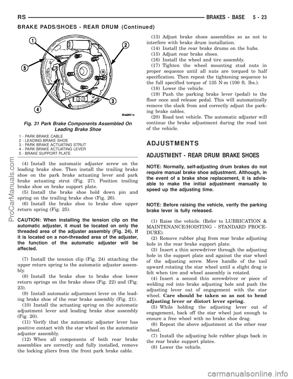
(4) Install the automatic adjuster screw on the
leading brake shoe. Then install the trailing brake
shoe on the park brake actuating lever and park
brake actuating strut (Fig. 27). Position trailing
brake shoe on brake support plate.
(5) Install the brake shoe hold down pin and
spring on the trailing brake shoe (Fig. 26).
(6) Install the brake shoe to brake shoe upper
return spring (Fig. 25).
CAUTION: When installing the tension clip on the
automatic adjuster, it must be located on only the
threaded area of the adjuster assembly (Fig. 24). If
it is located on a non-threaded area of the adjuster,
the function of the automatic adjuster will be
affected.
(7) Install the tension clip (Fig. 24) attaching the
upper return spring to the automatic adjuster assem-
bly.
(8) Install the brake shoe to brake shoe lower
return springs on the brake shoes (Fig. 22) and (Fig.
23).
(9) Install automatic adjustment lever on the lead-
ing brake shoe of the rear brake assembly (Fig. 21).
(10) Install the actuating spring on the automatic
adjustment lever and leading brake shoe assembly
(Fig. 20).
(11) Verify that the automatic adjuster lever has
positive contact with the star wheel on the automatic
adjuster assembly.
(12) When all components of both rear brake
assemblies are correctly and fully installed, remove
the locking pliers from the front park brake cable.(13) Adjust brake shoes assemblies so as not to
interfere with brake drum installation.
(14) Install the rear brake drums on the hubs.
(15) Adjust rear brake shoes.
(16) Install the wheel and tire assembly.
(17) Tighten the wheel mounting stud nuts in
proper sequence until all nuts are torqued to half
specification. Then repeat the tightening sequence to
the full specified torque of 135 N´m (100 ft. lbs.).
(18) Lower the vehicle.
(19) Push the parking brake lever (pedal) to the
floor once and release pedal. This will automatically
remove the slack from and correctly adjust the park-
ing brake cables.
(20) Road test vehicle. The automatic adjuster will
continue the brake adjustment during the road test
of the vehicle.
ADJUSTMENTS
ADJUSTMENT - REAR DRUM BRAKE SHOES
NOTE: Normally, self-adjusting drum brakes do not
require manual brake shoe adjustment. Although, in
the event of a brake shoe replacement, it is advis-
able to make the initial adjustment manually to
speed up the adjusting time.
NOTE: Before raising the vehicle, verify the parking
brake lever is fully released.
(1) Raise the vehicle. (Refer to LUBRICATION &
MAINTENANCE/HOISTING - STANDARD PROCE-
DURE).
(2) Remove rubber plug from rear brake adjusting
hole in the rear brake support plate.
(3) Insert a thin screwdriver through the adjusting
hole in the support plate and against the star wheel
of the adjusting screw. Move handle of the tool
upward rotating the star wheel until a slight drag is
felt when tire and wheel assembly is rotated.
(4) Insert a second thin screwdriver or piece of
welding rod into brake adjusting hole and push the
adjusting lever out of engagement with the star
wheel.Care should be taken so as not to bend
adjusting lever or distort lever spring.
(5) While holding the adjusting lever out of
engagement, back off the star wheel just enough to
ensure a free wheel with no brake shoe drag.
(6) Repeat the above adjustment at the other rear
wheel.
(7) Install the adjusting hole rubber plugs back in
the rear brake support plates.
(8) Lower the vehicle.
Fig. 31 Park Brake Components Assembled On
Leading Brake Shoe
1 - PARK BRAKE CABLE
2 - LEADING BRAKE SHOE
3 - PARK BRAKE ACTUATING STRUT
4 - PARK BRAKE ACTUATING LEVER
5 - BRAKE SUPPORT PLATE
RSBRAKES - BASE5-23
BRAKE PADS/SHOES - REAR DRUM (Continued)
ProCarManuals.com
Page 172 of 2177
master cylinder reservoir from completely draining
out.
(3) Disconnect the brake fluid flex hose from the
caliper assembly and remove it from the vehicle.
CAUTION: Do not use excessive force when clamp-
ing caliper in vise. Excessive vise pressure will
cause bore distortion.
(4) Mount the caliper in a vise equipped with pro-
tective jaws.
(5) Remove the piston dust boot from the caliper
and discard.
NOTE: Do not use a screw driver or other metal tool
for seal removal. Using such tools can scratch the
bore or leave burrs on the seal groove edges.
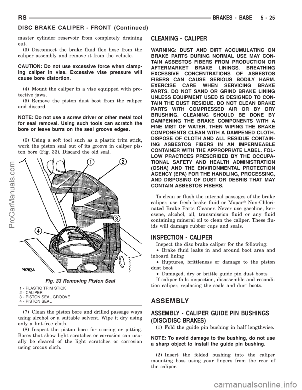
(6) Using a soft tool such as a plastic trim stick,
work the piston seal out of its groove in caliper pis-
ton bore (Fig. 33). Discard the old seal.
(7) Clean the piston bore and drilled passage ways
using alcohol or a suitable solvent. Wipe it dry using
only a lint-free cloth.
(8) Inspect the piston bore for scoring or pitting.
Bores that show light scratches or corrosion can usu-
ally be cleared of the light scratches or corrosion
using crocus cloth.CLEANING - CALIPER
WARNING: DUST AND DIRT ACCUMULATING ON
BRAKE PARTS DURING NORMAL USE MAY CON-
TAIN ASBESTOS FIBERS FROM PRODUCTION OR
AFTERMARKET BRAKE LININGS. BREATHING
EXCESSIVE CONCENTRATIONS OF ASBESTOS
FIBERS CAN CAUSE SERIOUS BODILY HARM.
EXERCISE CARE WHEN SERVICING BRAKE
PARTS. DO NOT SAND OR GRIND BRAKE LINING
UNLESS EQUIPMENT USED IS DESIGNED TO CON-
TAIN THE DUST RESIDUE. DO NOT CLEAN BRAKE
PARTS WITH COMPRESSED AIR OR BY DRY
BRUSHING. CLEANING SHOULD BE DONE BY
DAMPENING THE BRAKE COMPONENTS WITH A
FINE MIST OF WATER, THEN WIPING THE BRAKE
COMPONENTS CLEAN WITH A DAMPENED CLOTH.
DISPOSE OF CLOTH AND ALL RESIDUE CONTAIN-
ING ASBESTOS FIBERS IN AN IMPERMEABLE
CONTAINER WITH THE APPROPRIATE LABEL. FOL-
LOW PRACTICES PRESCRIBED BY THE OCCUPA-
TIONAL SAFETY AND HEALTH ADMINISTRATION
(OSHA) AND THE ENVIRONMENTAL PROTECTION
AGENCY (EPA) FOR THE HANDLING, PROCESSING,
AND DISPOSING OF DUST OR DEBRIS THAT MAY
CONTAIN ASBESTOS FIBERS.
To clean or flush the internal passages of the brake
caliper, use fresh brake fluid or MopartNon-Chlori-
nated Brake Parts Cleaner. Never use gasoline, ker-
osene, alcohol, oil, transmission fluid or any fluid
containing mineral oil to clean the caliper. These flu-
ids will damage rubber cups and seals.
INSPECTION - CALIPER
Inspect the disc brake caliper for the following:
²Brake fluid leaks in and around boot area and
inboard lining
²Ruptures, brittleness or damage to the piston
dust boot
²Damaged, dry or brittle guide pin dust boots
If caliper fails inspection, disassemble and recondi-
tion caliper, replacing the seals and dust boots.
ASSEMBLY
ASSEMBLY - CALIPER GUIDE PIN BUSHINGS
(DISC/DISC BRAKES)
(1) Fold the guide pin bushing in half lengthwise.
NOTE: To avoid damage to the bushing, do not use
a sharp object to install the guide pin bushing.
(2) Insert the folded bushing into the caliper
mounting boss using your fingers from the rear of
the caliper.
Fig. 33 Removing Piston Seal
1 - PLASTIC TRIM STICK
2 - CALIPER
3 - PISTON SEAL GROOVE
4 - PISTON SEAL
RSBRAKES - BASE5-25
DISC BRAKE CALIPER - FRONT (Continued)
ProCarManuals.com