location CHRYSLER CARAVAN 2005 Owners Manual
[x] Cancel search | Manufacturer: CHRYSLER, Model Year: 2005, Model line: CARAVAN, Model: CHRYSLER CARAVAN 2005Pages: 2339, PDF Size: 59.69 MB
Page 515 of 2339
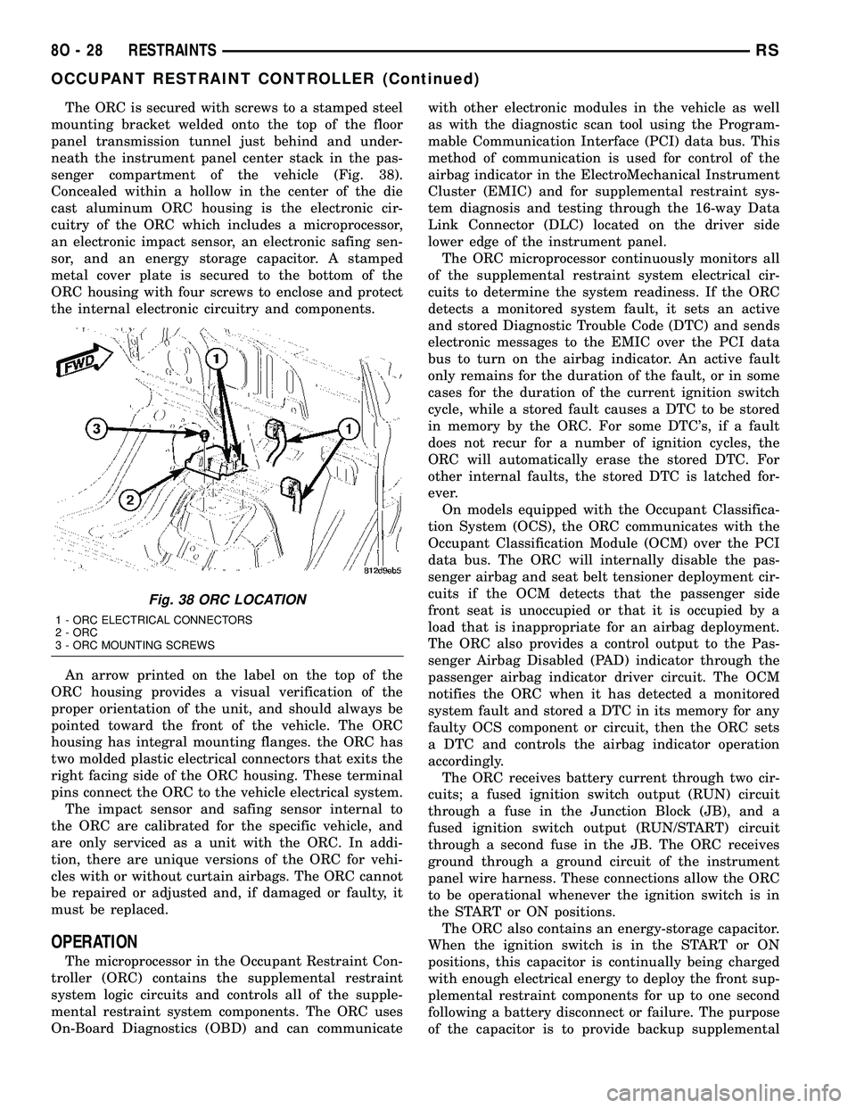
The ORC is secured with screws to a stamped steel
mounting bracket welded onto the top of the floor
panel transmission tunnel just behind and under-
neath the instrument panel center stack in the pas-
senger compartment of the vehicle (Fig. 38).
Concealed within a hollow in the center of the die
cast aluminum ORC housing is the electronic cir-
cuitry of the ORC which includes a microprocessor,
an electronic impact sensor, an electronic safing sen-
sor, and an energy storage capacitor. A stamped
metal cover plate is secured to the bottom of the
ORC housing with four screws to enclose and protect
the internal electronic circuitry and components.
An arrow printed on the label on the top of the
ORC housing provides a visual verification of the
proper orientation of the unit, and should always be
pointed toward the front of the vehicle. The ORC
housing has integral mounting flanges. the ORC has
two molded plastic electrical connectors that exits the
right facing side of the ORC housing. These terminal
pins connect the ORC to the vehicle electrical system.
The impact sensor and safing sensor internal to
the ORC are calibrated for the specific vehicle, and
are only serviced as a unit with the ORC. In addi-
tion, there are unique versions of the ORC for vehi-
cles with or without curtain airbags. The ORC cannot
be repaired or adjusted and, if damaged or faulty, it
must be replaced.
OPERATION
The microprocessor in the Occupant Restraint Con-
troller (ORC) contains the supplemental restraint
system logic circuits and controls all of the supple-
mental restraint system components. The ORC uses
On-Board Diagnostics (OBD) and can communicatewith other electronic modules in the vehicle as well
as with the diagnostic scan tool using the Program-
mable Communication Interface (PCI) data bus. This
method of communication is used for control of the
airbag indicator in the ElectroMechanical Instrument
Cluster (EMIC) and for supplemental restraint sys-
tem diagnosis and testing through the 16-way Data
Link Connector (DLC) located on the driver side
lower edge of the instrument panel.
The ORC microprocessor continuously monitors all
of the supplemental restraint system electrical cir-
cuits to determine the system readiness. If the ORC
detects a monitored system fault, it sets an active
and stored Diagnostic Trouble Code (DTC) and sends
electronic messages to the EMIC over the PCI data
bus to turn on the airbag indicator. An active fault
only remains for the duration of the fault, or in some
cases for the duration of the current ignition switch
cycle, while a stored fault causes a DTC to be stored
in memory by the ORC. For some DTC's, if a fault
does not recur for a number of ignition cycles, the
ORC will automatically erase the stored DTC. For
other internal faults, the stored DTC is latched for-
ever.
On models equipped with the Occupant Classifica-
tion System (OCS), the ORC communicates with the
Occupant Classification Module (OCM) over the PCI
data bus. The ORC will internally disable the pas-
senger airbag and seat belt tensioner deployment cir-
cuits if the OCM detects that the passenger side
front seat is unoccupied or that it is occupied by a
load that is inappropriate for an airbag deployment.
The ORC also provides a control output to the Pas-
senger Airbag Disabled (PAD) indicator through the
passenger airbag indicator driver circuit. The OCM
notifies the ORC when it has detected a monitored
system fault and stored a DTC in its memory for any
faulty OCS component or circuit, then the ORC sets
a DTC and controls the airbag indicator operation
accordingly.
The ORC receives battery current through two cir-
cuits; a fused ignition switch output (RUN) circuit
through a fuse in the Junction Block (JB), and a
fused ignition switch output (RUN/START) circuit
through a second fuse in the JB. The ORC receives
ground through a ground circuit of the instrument
panel wire harness. These connections allow the ORC
to be operational whenever the ignition switch is in
the START or ON positions.
The ORC also contains an energy-storage capacitor.
When the ignition switch is in the START or ON
positions, this capacitor is continually being charged
with enough electrical energy to deploy the front sup-
plemental restraint components for up to one second
following a battery disconnect or failure. The purpose
of the capacitor is to provide backup supplemental
Fig. 38 ORC LOCATION
1 - ORC ELECTRICAL CONNECTORS
2 - ORC
3 - ORC MOUNTING SCREWS
8O - 28 RESTRAINTSRS
OCCUPANT RESTRAINT CONTROLLER (Continued)
Page 516 of 2339
restraint system protection in case there is a loss of
battery current supply to the ORC during an impact.
Two sensors are contained within the ORC, an
electronic impact sensor and a safing sensor. The
ORC also monitors inputs from eight remote impact
sensors. Two front impact sensors are located on each
outboard side of the lower radiator support, and
three side impact sensors are located on each side of
the vehicle at the B-pillar, in the lower sliding door
opening in front of the C-pillar, and over the rear
wheel well between the C and D-pillars. The elec-
tronic impact sensors are accelerometers that sense
the rate of vehicle deceleration, which provides veri-
fication of the direction and severity of an impact.
The safing sensor is an electronic accelerometer
sensor within the ORC that provides an additional
logic input to the ORC microprocessor. The safing
sensor is used to verify the need for a supplemental
restraint deployment by detecting impact energy of a
lesser magnitude than that of the primary electronic
impact sensors, and must exceed a safing threshold
in order for the airbags to deploy. Vehicles equipped
with curtain airbags, there is a second safing sensor
within the ORC to provide confirmation to the ORC
microprocessor of side impact forces. This second saf-
ing sensor is a bi-directional unit that detects impact
forces from either side of the vehicle.
Pre-programmed decision algorithms in the ORC
microprocessor determine when the deceleration rate
as signaled by the impact sensors and the safing sen-
sors indicate an impact that is severe enough to
require supplemental restraint system protection
and, based upon the severity of the monitored
impact, determines the level of front airbag deploy-
ment force required for each front seating position.
When the programmed conditions are met, the ORC
sends the proper electrical signals to deploy the dual
multistage front airbags at the programmed force
levels, the front seat belt tensioners and, if the vehi-
cle is so equipped, either curtain airbag. For vehicles
equipped with the OCS, the passenger front airbag
and seat belt tensioner will be deployed by the ORC
only if enabled by the OCM messages (PAD indicator
OFF) at the time of the impact.
To diagnose and test the ORC and all airbag sys-
tem components, use a scan tool and the appropriate
diagnostic information.
REMOVAL
WARNING: Never replace both the Occupant
Restraint Controller (ORC) and the Occupant Clas-
sification Module (OCM) at the same time. If both
require replacement, replace one, then perform the
Airbag System test (Refer to 8 - ELECTRICAL/RE-
STRAINTS - DIAGNOSIS AND TESTING - AIRBAGSYSTEM) before replacing the other. Both the ORC
and the OCM store Occupant Classification System
(OCS) calibration data, which they transfer to one
another when one of them is replaced. If both are
replaced at the same time, an irreversible fault will
be set in both modules and the OCS may malfunc-
tion and result in personal injury or death.
(1) Disconnect and isolate the battery negative
cable.
(2)
WARNING: Wait two minutes for the airbag system
reserve capacitor to discharge before beginning
any airbag system or component service. Failure to
do so may result in accidental airbag deployment,
personal injury or death.
(3) Remove storage bin from instrument panel
(Refer to 23 - BODY/INSTRUMENT PANEL/STOR-
AGE BIN - REMOVAL).
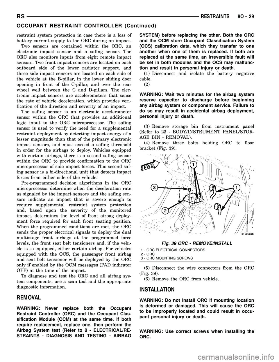
(4) Remove three bolts holding ORC to floor
bracket (Fig. 39).
(5) Disconnect the wire connectors from the ORC
(Fig. 39).
(6) Remove the ORC from vehicle.
INSTALLATION
WARNING: Do not install ORC if mounting location
is deformed or damaged. This will cause the ORC
to be improperly located and could result in occu-
pant personal injury or death.
WARNING: Use correct screws when installing the
ORC.
Fig. 39 ORC - REMOVE/INSTALL
1 - ORC ELECTRICAL CONNECTORS
2 - ORC
3 - ORC MOUNTING SCREWS
RSRESTRAINTS8O-29
OCCUPANT RESTRAINT CONTROLLER (Continued)
Page 540 of 2339
The SKREES can be diagnosed and any stored DTC's
can be retrieved using a DRBllltscan tool as
described in the appropriate Body Diagnostic Proce-
dures information.
DIAGNOSIS AND TESTING
DIAGNOSIS AND TESTING - SENTRY KEY
REMOTE ENTRY SYSTEM
WARNING: On vehicles equipped with airbags, refer
to electrical, restraints, warnings, before attempting
component diagnosis or service. Failure to take the
proper precautions could result in accidental airbag
deployment and possible personal injury or death.
NOTE: The following tests may not prove conclu-
sive in the diagnosis of this system. The most reli-
able, efficient, and accurate means to diagnose the
Sentry Key Remote Entry System (SKREES)
involves the use of a DRBIIITscan tool. Refer to the
proper Body Diagnostic Procedures information.
The Sentry Key Remote Entry System (SKREES)
and the Programmable Communication Interface
(PCI) bus network should be diagnosed using a scan
tool. The scan tool will allow confirmation that the
PCI bus is functional, that the Sentry Key Remote
Entry Module (SKREEM) is placing the proper mes-
sages on the PCI bus, and that the Powertrain Con-
trol Module (PCM) is receiving the PCI bus
messages. Refer to the proper Body Diagnostic Proce-
dures information, and Wiring Diagrams for complete
circuit descriptions and diagrams.
(1) Check the fuses in the Integrated Power Mod-
ule (IPM). If OK, go to Step 2. If not OK, repair the
shorted circuit or component as required and replace
the faulty fuse.
(2) Disconnect and isolate the battery negative
remote cable from the remote terminal. Unplug the
wire harness connector at the SKREEM. Check for
continuity between the ground circuit cavity of the
SKREEM wire harness connector and a good ground.
There should be continuity. If OK, go to Step 3. If not
OK, repair the open circuit to ground as required.
(3) Connect the battery negative cable. Check for
battery voltage at the fused B(+) circuit cavity of the
SKREEM wire harness connector. If OK, go to Step
4. If not OK, repair the open circuit to the fuse in the
IPM as required.
(4) Turn the ignition switch to the ON position.
Check for battery voltage at the fused ignition switch
output (run/start) circuit cavity of the SKREEM wire
harness connector. If OK, use a scan tool and the
proper Body Diagnostic Procedures information tocomplete the diagnosis of the SKREES. If not OK,
repair the open circuit to the fuse in the IPM as
required.
DIAGNOSIS AND TESTING - VEHICLE THEFT
SECURITY SYSTEM
Refer to the appropriate wiring information. The
wiring information includes wiring diagrams, proper
wire and connector repair procedures, further details
on wire harness routing and retention, as well as
pin-out and location views for the various wire har-
ness connectors, splices and grounds. Using a
DRBIIItscan tool. Refer to the proper Body Diagnos-
tic Procedures information for test procedures.
HOOD AJAR SWITCH -
EXPORT
REMOVAL
(1) Disconnect and isolate the battery negative
cable.
(2) Using a small flat blade screwdriver, pry trig-
ger switch from the bracket on the left fender well.
(3) Disconnect the hood ajar switch from the wire
connector and remove from vehicle.
INSTALLATION
(1) Connect the hood ajar switch to the wire conec-
tor.
(2) Press the hood ajar switch into position on the
bracket located on the left inner fender well.
(3) Reconnect the battery negative cable.
(4) Close the hood and check for proper operation.
SENTRY KEY REMOTE ENTRY
MODULE
DESCRIPTION
The Sentry Key Remote Entry Module (SKREEM)
performs the functions of the Sentry Key Immobilizer
Module (SKIM), Remote Keyless Entry (RKE) Mod-
ule, and the Tire Pressure Monitoring (TPM) System
(previously part of the Electronic Vehicle Information
Center (EVIC).
The SKREEM is located in the same location as
the SKIM was and is mounted the same way. It looks
identical, but has added capabilities.
SENTRY KEY IMMOBILIZER
The Sentry Key Immobilizer System (SKIS)
authenticates an electronically coded Transponder
Key placed into the ignition and sends a valid/invalid
key message to the Powertrain Control Module
RSVEHICLE THEFT SECURITY8Q-3
VEHICLE THEFT SECURITY (Continued)
Page 541 of 2339
(PCM) based upon the results. The ªVALID/INVALID
KEYº message communication is performed using a
rolling code algorithm via the Programmable Com-
munication Interface (PCI) data bus. A ªVALID KEYº
message must be sent to the Powertrain Control
Module (PCM) within two seconds of ignition ON to
free the engine from immobilization.
The SKREEM contains a Radio Frequency (RF)
transceiver and a microprocessor. The SKREEM
retains in memory the ID numbers of any Sentry Key
that is programmed to it. The maximum number of
keys that may be programmed to each module is
eight (8). The SKREEM also communicates over the
Programmable Communication Interface (PCI) data
bus with the Powertrain Control Module (PCM), the
Body Control Module (BCM), the Mechanical Instru-
ment Cluster (MIC), and the DRB IIItscan tool. The
SKREEM transmits and receives RF signals through
a tuned antenna enclosed within a molded plastic
ring formation that is integral to the SKREEM hous-
ing. When the SKREEM is properly installed on the
steering column, the antenna ring fits snugly around
the circumference of the ignition lock cylinder hous-
ing. If this ring is not mounted properly, communica-
tion problems may arise in the form of transponder-
related faults.
For added system security, each SKREEM is pro-
grammed with a unique9Secret Key9code. This code
is stored in memory and is sent over the PCI bus to
the PCM and to each key that is programmed to
work with the vehicle. The9Secret Key9code is there-
fore a common element found in all components of
the Sentry Key Immobilizer System (SKIS). In the
event that a SKREEM replacement is required, the
9Secret Key9code can be restored from the PCM by
following the SKIM replacement procedure found in
the DRB IIItscan tool. Proper completion of this
task will allow the existing ignition keys to be repro-
grammed. Therefore, new keys will NOT be needed.
In the event that the original9Secret Key9code can
not be recovered, new ignition keys will be required.
The DRB IIItscan tool will alert the technician if
key replacement is necessary. Another security code,
called a PIN, is used to gain secured access to the
SKREEM for service. The SKREEM also stores in its
memory the Vehicle Identification Number (VIN),
which it learns through a bus message from the
assembly plant tester. The SKIS scrambles the infor-
mation that is communicated between its components
in order to reduce the possibility of unauthorized
SKREEM access and/or disabling.
REMOTE KEYLESS ENTRY (RKE)
The RKE transmitter uses radio frequency signals
to communicate with the SKREEM. The SKREEM is
on the PCI bus. When the operator presses a buttonon the transmitter, it sends a specific request to the
SKREEM. In turn the SKREEM sends the appropri-
ate request over the PCI Bus to the:
²Body Control Module (BCM) to control the door
lock and unlock functions, the liftgate lock and
unlock functions, the arming and disarming of the
Vehicle Theft Security System (VTSS) (if equipped),
and the activation of illuminated entry.
²Integrated Power Module (IPM) to activate the
park lamps, the headlamps, and the horn for horn
chirp. If requested, the BCM sends a request over
the PCI Bus to the:
TIRE PRESSURE MONITORING (TPM)
If equipped with the Tire Pressure Monitoring
(TPM) System, each of the vehicles four wheels will
have a valve stem with a pressure sensor and radio
transmitter built in. Signals from the tire pressure
sensor/transmitter are received and interpreted by
the SKREEM.
A sensor/transmitter in a mounted wheel will
broadcast its detected pressure once per minute
when the vehicle is moving faster than 15 mph (24
km/h). Each sensor/transmitter's broadcast is
uniquely coded so that the SKREEM can determine
the location.
OPERATION
SENTRY KEY IMMOBILIZER
The Sentry Key Remote Entry Module (SKREEM)
receives an encrypted Radio Frequency (RF) signal
from the transponder key. The SKREEM then
decrypts the signal and broadcasts the requested
remote commands to the appropriate modules in the
vehicle over the Programmable Communication
Interface (PCI) data bus. A valid transponder key ID
must be incorporated into the RF signal in order for
the SKREEM to pass the message on to the appro-
priate modules.
Automatic transponder key synchronization is done
by the SKREEM if a valid transponder key is
inserted into the ignition cylinder, and the ignition is
turned ON. This provides a maximum operation win-
dow for RKE functions.
Each Sentry Key Remote Entry System (SKREES)
consists of a SKREEM and a transponder key. Each
system has a secret key code unique to that system.
The secret key is electronically coded in the
SKREEM and in all programmed transponder keys.
It is used for immobilization and RKE functions for
data security. In addition, each transponder key will
have a unique identification. For North America, the
options are a 3-button or 6 button integrated keys.
For Export, the options are 2-button or 5 button key
fobs. (Export does not get the integrated key).
8Q - 4 VEHICLE THEFT SECURITYRS
SENTRY KEY REMOTE ENTRY MODULE (Continued)
Page 547 of 2339
OPERATION
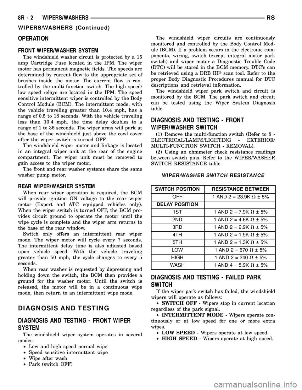
FRONT WIPER/WASHER SYSTEM
The windshield washer circuit is protected by a 15
amp Cartridge Fuse located in the IPM. The wiper
motor has permanent magnetic fields. The speeds are
determined by current flow to the appropriate set of
brushes inside the motor. The current flow is con-
trolled by the multi-function switch. The high speed/
low speed relays are located in the IPM. The speed
sensitive intermittent wiper is controlled by the Body
Control Module (BCM). The intermittent mode, with
the vehicle traveling greater than 10.4 mph, has a
range of 0.5 to 18 seconds. With the vehicle traveling
less than 10.4 mph, the time delay doubles to a
range of 1 to 36 seconds. The wiper arms will park at
the base of the windshield just above the cowl cover
after the wiper switch is turned OFF.
The windshield wiper motor and linkage is located
in an integral wiper unit at the rear of the engine
compartment. The wiper unit must be removed to
gain access to the wiper motor.
The front and rear washer systems share the same
washer pump motor.
REAR WIPER/WASHER SYSTEM
When rear wiper operation is required, the BCM
will provide ignition ON voltage to the rear wiper
motor (Export and ATC equipped vehicles only).
When the wiper switch is turned OFF, the BCM pro-
vides circuit ground to operate the motor until the
wipe cycle is complete and the wiper arm returns to
the base of the rear window.
Switch only offers an intermittent rear wiper
mode. The wiper motor will cycle every 7 seconds.
The intermittent delay time is also adjusted based
upon vehicle speed. With the vehicle traveling
greater than 50 mph, the cycle changes to every 5
seconds.
When rear washer is requested by depressing and
holding down the switch, the BCM then provides a
ground for the washer motor. Until the switch is
released, the motor will be in a continuous wipe
mode, then return to an intermittent wipe mode.
DIAGNOSIS AND TESTING
DIAGNOSIS AND TESTING - FRONT WIPER
SYSTEM
The windshield wiper system operates in several
modes:
²Low and high speed normal wipe
²Speed sensitive intermittent wipe
²Wipe after wash
²Park (switch OFF)The windshield wiper circuits are continuously
monitored and controlled by the Body Control Mod-
ule (BCM). If a problem occurs in the electronic com-
ponents, wiring, switch (except integral motor park
switch) and wiper motor a Diagnostic Trouble Code
(DTC) will be stored in the BCM memory. DTC's can
be retrieved using a DRB IIItscan tool. Refer to the
proper Body Diagnostic Procedures manual for DTC
descriptions and retrieval information.
The windshield wiper park switch and circuit is
monitored by the BCM. The park switch and circuit
can be tested using the Wiper System Diagnosis
table.
DIAGNOSIS AND TESTING - FRONT
WIPER/WASHER SWITCH
(1) Remove the multi-function switch (Refer to 8 -
ELECTRICAL/LAMPS/LIGHTING - EXTERIOR/
MULTI-FUNCTION SWITCH - REMOVAL).
(2) Using an ohmmeter check resistance readings
between switch pins. Refer to the WIPER/WASHER
SWITCH RESISTANCE table.
WIPER/WASHER SWITCH RESISTANCE
SWITCH POSITION RESISTANCE BETWEEN
OFF 1 AND 2 = 23.9KV 5%
DELAY POSITION
1ST 1 AND 2 = 7.9KV 5%
2ND 1 AND 2 = 4.6KV 5%
3RD 1 AND 2 = 2.9KV 5%
4TH 1 AND 2 = 1.9KV 5%
5TH 1 AND 2 = 1.3KV 5%
LOW 1 AND 2 = 670V 5%
HIGH 1 AND2=240V 5%
WASH 1 AND 4 = 5.9KV 5%
DIAGNOSIS AND TESTING - FAILED PARK
SWITCH
If the wiper park switch has failed, the windshield
wipers will operate as follows:
²SWITCH OFF- Wipers stop in current location
regardless of the park signal.
²INTERMITTENT MODE- Wipers operate con-
tinuously or at low speed for one or more extra
wipes.
²LOW SPEED- Wipers operate at low speed.
²HIGH SPEED- Wipers operate at high speed.
8R - 2 WIPERS/WASHERSRS
WIPERS/WASHERS (Continued)
Page 556 of 2339
OPERATION
When rear wiper operation is required, the BCM
will provide ignition ON voltage to the rear wiper
motor. When the wiper switch is turned OFF, the
BCM provides circuit ground to operate the motor
until the wipe cycle is complete and the wiper arm
returns to the base of the rear window.
The rear wiper/washer switch only offers an inter-
mittent rear wiper mode. The wiper motor will cycle
every 7 seconds. The intermittent delay time is also
adjusted based upon vehicle speed. With the vehicle
traveling greater than 50 mph, the cycle changes to
every 5 seconds.
When rear washer is requested by depressing and
holding down the switch, the BCM then provides a
ground for the rear washer motor. Until the switch is
released, the motor will be in a continuous wipe
mode, then return to an intermittent wipe mode.
WASHER FLUID LEVEL
SWITCH
REMOVAL
(1) Disconnect and isolate the battery negative
cable.
(2) Hoist and support vehicle on hoist or jack
stands.
(3) If necessary, remove the right front wheel and
tire assembly (Refer to 22 - TIRES/WHEELS -
REMOVAL).
(4) Disconnect the right front wheelhouse splash
shield and move aside (Refer to 23 - BODY/EXTERI-
OR/WHEELHOUSE SPLASH SHIELD - REMOVAL).
(5) Drain washer fluid from the reservoir and into
a suitable clean container. This can be done by dis-connecting the windshield washer hose from the
front (outboard) washer pump port allowing the
washer fluid to drain into a container through a tem-
porary jumper hose connected to the front washer
pump.
(6) Disconnect the electrical body harness connec-
tor to the the fluid level sensor. Slide the red lock on
the connector to the release position, then, depress
the black tab and pull the connector off the sensor.
(7) Remove the sensor from reservoir by using a
side foot to gently pry the sensor from the body of
the reservoir. Do not damage the reservoir/sensor
sealing surface or puncture reservoir during removal.
CAUTION: To avoid damage to the sensor, assure
the reservoir is in an upright position before remov-
ing the sensor from the reservoir. Do not rotate the
sensor during removal.
INSTALLATION
(1) Use a new grommet when installing a new sen-
sor assembly.
(2) Assure that the flat of the sensor is aligned
under the ridge of the reservoir and that the sensor
connector is facing down in the fully seated position.
This will allow for proper operation of the sensor
float switch.
(3) Connect the electrical body harness connectors
to the fluid level sensor. Slide the red lock on the
connector to the closed or locked position.
(4) Assure that washer hose is properly routed to
prevent pinching and possible inoperative washers.
(5) Connect the left right front wheelhouse splash
shield and move aside (Refer to 23 - BODY/EXTERI-
OR/WHEELHOUSE SPLASH SHIELD - INSTALLA-
TION).
(6) Install the right front wheel and tire assembly
(Refer to 22 - TIRES/WHEELS - INSTALLATION).
(7) lower vehicle from hoist or jack stands.
(8) Connect the battery negative cable.
(9) Verify system operation.
WASHER HOSES
REMOVAL
(1) Remove washer reservoir from vehicle (Refer to
8 - ELECTRICAL/WIPERS/WASHERS/WASHER
RESERVOIR - REMOVAL).
(2) Disconnect washer hose front the reservoir cav-
ity.
(3) Disconnect the washer hose from the reservoir
pump.
(4) Remove parts as necessary to replace washer
hose (engine compartment, interior components, etc.).
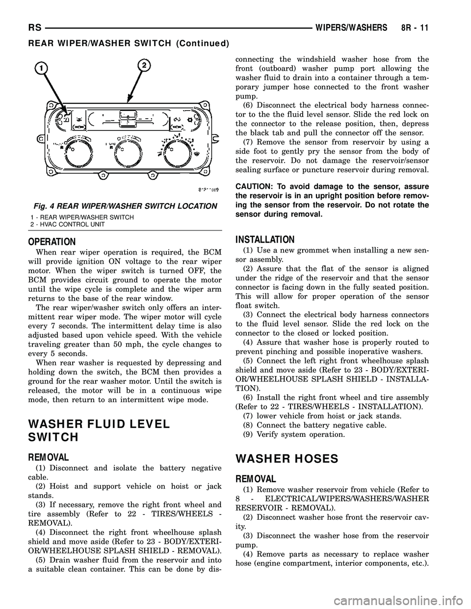
Fig. 4 REAR WIPER/WASHER SWITCH LOCATION
1 - REAR WIPER/WASHER SWITCH
2 - HVAC CONTROL UNIT
RSWIPERS/WASHERS8R-11
REAR WIPER/WASHER SWITCH (Continued)
Page 560 of 2339
NAVIGATION/TELECOMMUNICATION
TABLE OF CONTENTS
page page
NAVIGATION/TELECOMMUNICATION
DESCRIPTION..........................1
OPERATION............................1
DIAGNOSIS AND TESTING
TELECOMMUNICATION.................1HANDS FREE MODULE
REMOVAL.............................3
INSTALLATION..........................3
NAVIGATION/
TELECOMMUNICATION
DESCRIPTION
TELECOMMUNICATIONS
A hands-free cellular system is an available option
on this vehicle. It uses BluetoothŸ technology to pro-
vide wireless communication between the operator's
compatible cellular telephone and the vehicle's
on-board receiver.
The system uses voice recognition technology to
control operation. The incoming voice is broadcast
through the vehicle's radio speakers, automatically
overriding any other audio signals on the speakers
when the hands-free system is in use. A microphone
in the rearview mirror picks up vehicle occupant's
voices. If a call is in progress when the ignition is
switched off, the hands-free system will continue to
operate for up to 45 seconds as part of the Accessory
Relay Delay function. Thereafter, the call can con-
tinue on the hand-held telephone.
The center console front storage compartment
includes a cellular telephone holder, but the system
will communicate with a telephone that is anywhere
within the vehicle. However, covering the hand held
phone or the hands-free phone module with a metal
object may block the signal. The system will recog-
nize up to seven telephones, each of which is given a
spoken identification by the user during the setup
process. The system includes Spanish voice recogni-
tion in addition to English.
Two buttons on the rearview mirror, identified with
ISO icons, control the system: A9phone9button turns
the system on and off; a9voice recognition9(or voice
command) button prompts the hands-free system to
listen for a voice command.
OPERATION
TELECOMMUNICATION
Two buttons on the rearview mirror, identified with
ISO icons, control the system: A9phone9button turns
the system on and off; a9voice recognition9(or voice
command) button prompts the hands-free system to
listen for a voice command. The system includes the
following features:
²Phonebook - Stores telephone numbers for later
recall by name or other verbal identification, called a
voice tag, and memory location.
²Four memory locations - Home, Work, Mobile
and Pager. A maximum of 32 unique names or voice
tags may be stored at the same time, with a different
number in each of the four memory locations.
²Voice tag dialing - Dials the number associated
with a voice tag and memory location.
²Digit dialing - Dials the telephone number by
recognizing the names of the digits as they are spo-
ken.
²Receiving calls - A voice prompt notifies the user
of an incoming call. Pressing the ªphoneº button
answers the call.
²Privacy Mode - Switches the call to the hand-
held telephone and the hands-free system and back
again using the ªvoice recognitionº (or ªvoice com-
mandº) button and a voice command, if desired.
DIAGNOSIS AND TESTING
TELECOMMUNICATION
Any diagnosis of the Telecommunication sys-
tem should begin with the use of the DRB IIIt
diagnostic tool. For information on the use of
the DRB IIIt, refer to the appropriate Diagnos-
tic Service Information.
For complete circuit diagrams, refer to the appro-
priate wiring information.
RSNAVIGATION/TELECOMMUNICATION8T-1
Page 561 of 2339
WARNING: ON VEHICLES EQUIPPED WITH AIR-
BAGS, REFER TO ELECTRICAL, RESTRAINTS
BEFORE ATTEMPTING ANY STEERING WHEEL,
STEERING COLUMN, OR INSTRUMENT PANELCOMPONENT DIAGNOSIS OR SERVICE. FAILURE
TO TAKE THE PROPER PRECAUTIONS COULD
RESULT IN ACCIDENTAL AIRBAG DEPLOYMENT
AND POSSIBLE PERSONAL INJURY.
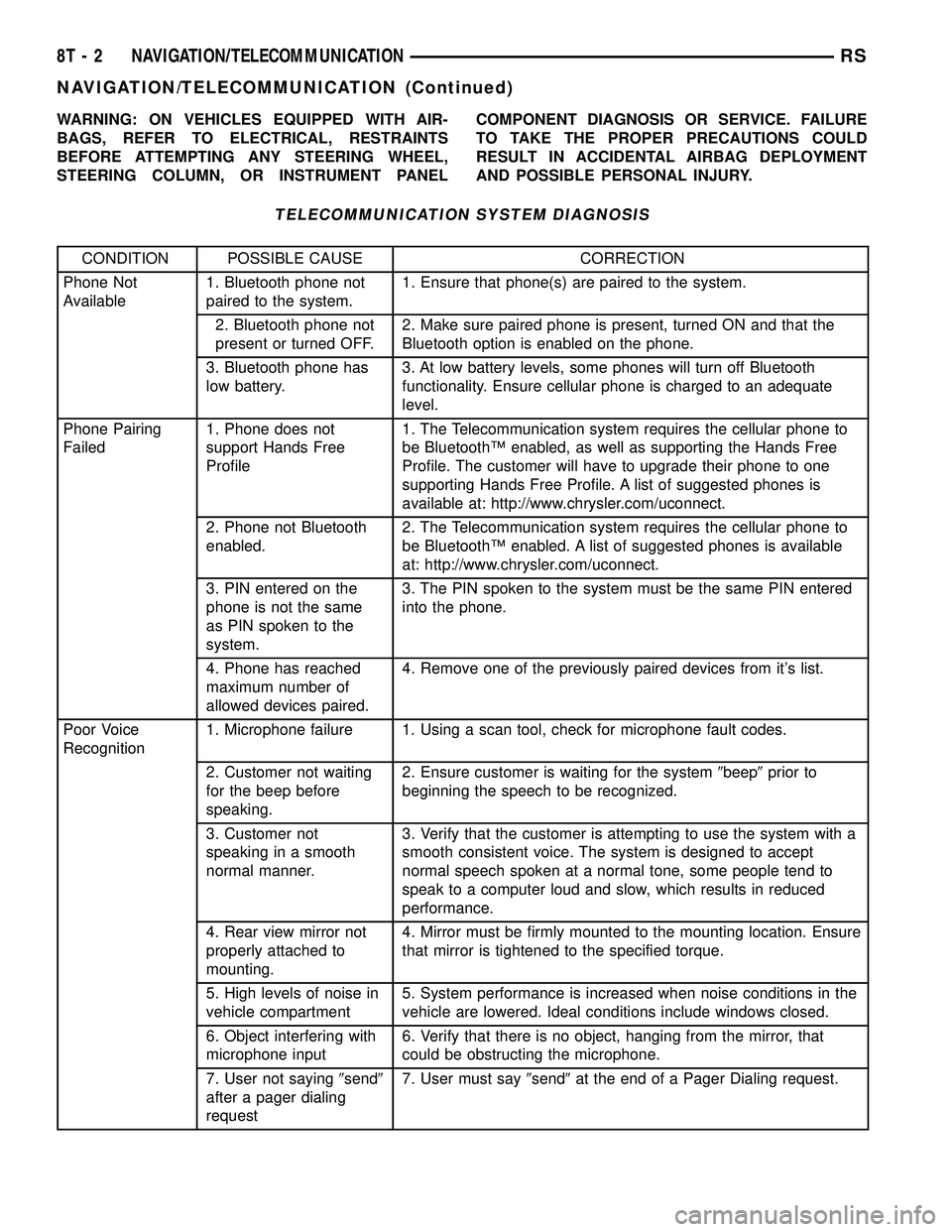
TELECOMMUNICATION SYSTEM DIAGNOSIS
CONDITION POSSIBLE CAUSE CORRECTION
Phone Not
Available1. Bluetooth phone not
paired to the system.1. Ensure that phone(s) are paired to the system.
2. Bluetooth phone not
present or turned OFF.2. Make sure paired phone is present, turned ON and that the
Bluetooth option is enabled on the phone.
3. Bluetooth phone has
low battery.3. At low battery levels, some phones will turn off Bluetooth
functionality. Ensure cellular phone is charged to an adequate
level.
Phone Pairing
Failed1. Phone does not
support Hands Free
Profile1. The Telecommunication system requires the cellular phone to
be BluetoothŸ enabled, as well as supporting the Hands Free
Profile. The customer will have to upgrade their phone to one
supporting Hands Free Profile. A list of suggested phones is
available at: http://www.chrysler.com/uconnect.
2. Phone not Bluetooth
enabled.2. The Telecommunication system requires the cellular phone to
be BluetoothŸ enabled. A list of suggested phones is available
at: http://www.chrysler.com/uconnect.
3. PIN entered on the
phone is not the same
as PIN spoken to the
system.3. The PIN spoken to the system must be the same PIN entered
into the phone.
4. Phone has reached
maximum number of
allowed devices paired.4. Remove one of the previously paired devices from it's list.
Poor Voice
Recognition1. Microphone failure 1. Using a scan tool, check for microphone fault codes.
2. Customer not waiting
for the beep before
speaking.2. Ensure customer is waiting for the system9beep9prior to
beginning the speech to be recognized.
3. Customer not
speaking in a smooth
normal manner.3. Verify that the customer is attempting to use the system with a
smooth consistent voice. The system is designed to accept
normal speech spoken at a normal tone, some people tend to
speak to a computer loud and slow, which results in reduced
performance.
4. Rear view mirror not
properly attached to
mounting.4. Mirror must be firmly mounted to the mounting location. Ensure
that mirror is tightened to the specified torque.
5. High levels of noise in
vehicle compartment5. System performance is increased when noise conditions in the
vehicle are lowered. Ideal conditions include windows closed.
6. Object interfering with
microphone input6. Verify that there is no object, hanging from the mirror, that
could be obstructing the microphone.
7. User not saying9send9
after a pager dialing
request7. User must say9send9at the end of a Pager Dialing request.
8T - 2 NAVIGATION/TELECOMMUNICATIONRS
NAVIGATION/TELECOMMUNICATION (Continued)
Page 562 of 2339
CONDITION POSSIBLE CAUSE CORRECTION
8. Other passengers
talking while customer is
attempting to use the
system8. Although designed for primary use by the driver, the
microphone will pick up passengers in any seat of the vehicle.
System performance is increased in low noise environments.
Phonebook
names not
recognized
consistently1. Phonebook names
recorded in high noise
conditions1. For increased system performance, it is recommended that the
phone book entries are recorded in a low noise environment. That
is, vehicle in park, with windows up.
2. Phonebook name(s)
short2. For increased performance it is recommended that the user
use both first and last name as a phonebook entry. Example9
Daniel James9as opposed to9Dan9.
3. Phonebook names
recorded by another user3. It is recommended that each user of the system record their
own phonebook entries. This will increase the recognition
performance.
4. Similar names in
phonebook4. For increased system performance it is recommended that the
user do not enter similar sounding names in the phonebook.
5. Object interfering with
microphone input5. Object interfering with microphone input.
Poor Phone
audio quality.1. Microphone failure 1. Use a scan tool, and check for Microphone faults.
2. Rear view mirror not
properly fixed to
mounting button2. Mirror must be firmly mounted to the mounting location. Tighten
mirror to the specified torque.
3. System being used in
high noise conditions3. System performance is increased when noise conditions in the
vehicle are lowered. Ideal conditions include windows closed.
No Phone Audio 1. Phone setting cause
phone audio to be routed
to handset.1. Route audio to9Hands free9device.
HANDS FREE MODULE
REMOVAL
(1) Disconnect and isolate the battery negative
cable.
(2) Remove the instrument panel lower console
(Refer to 23 - BODY/INSTRUMENT PANEL/STOR-
AGE BIN - REMOVAL).
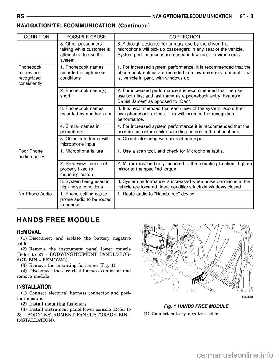
(3) Remove the mounting fasteners (Fig. 1).
(4) Disconnect the electrical harness connector and
remove module.
INSTALLATION
(1) Connect electrical harness connector and posi-
tion module.
(2) Install mounting fasteners.
(3) Install instrument panel lower console (Refer to
23 - BODY/INSTRUMENT PANEL/STORAGE BIN -
INSTALLATION).(4) Connect battery negative cable.
Fig. 1 HANDS FREE MODULE
RSNAVIGATION/TELECOMMUNICATION8T-3
NAVIGATION/TELECOMMUNICATION (Continued)
Page 564 of 2339

WIRING
TABLE OF CONTENTS
page page
WIRING DIAGRAM INFORMATION....... 8W-01-1
COMPONENT INDEX.................. 8W-02-1
POWER DISTRIBUTION............... 8W-10-1
GROUND DISTRIBUTION.............. 8W-15-1
BUS COMMUNICATIONS.............. 8W-18-1
CHARGING SYSTEM.................. 8W-20-1
STARTING SYSTEM.................. 8W-21-1
FUEL/IGNITION SYSTEM.............. 8W-30-1
TRANSMISSION CONTROL SYSTEM..... 8W-31-1
VEHICLE SPEED CONTROL............ 8W-33-1
ANTILOCK BRAKES................... 8W-35-1
VEHICLE THEFT SECURITY SYSTEM..... 8W-39-1
INSTRUMENT CLUSTER............... 8W-40-1
HORN/CIGAR LIGHTER/POWER OUTLET . . 8W-41-1
AIR CONDITIONING-HEATER........... 8W-42-1
OCCUPANT RESTRAINT SYSTEM........ 8W-43-1
INTERIOR LIGHTING.................. 8W-44-1
BODY CONTROL MODULE............. 8W-45-1
MESSAGE CENTER................... 8W-46-1
AUDIO SYSTEM..................... 8W-47-1REAR WINDOW DEFOGGER............ 8W-48-1
OVERHEAD CONSOLE................. 8W-49-1
FRONT LIGHTING.................... 8W-50-1
REAR LIGHTING..................... 8W-51-1
TURN SIGNALS...................... 8W-52-1
WIPERS............................ 8W-53-1
TRAILER TOW....................... 8W-54-1
NAVIGATION/TELECOMMUNICATIONS.... 8W-55-1
CONVENIENCE SYSTEMS.............. 8W-56-1
POWER WINDOWS................... 8W-60-1
POWER DOOR LOCKS................ 8W-61-1
POWER MIRRORS................... 8W-62-1
POWER SEATS...................... 8W-63-1
POWER SUNROOF................... 8W-64-1
SPLICE INFORMATION................ 8W-70-1
CONNECTOR PIN-OUTS............... 8W-80-1
CONNECTOR/GROUND/SPLICE
LOCATION........................ 8W-91-1
POWER DISTRIBUTION SYSTEM........ 8W-97-1 RSWIRING
8W-1