location CHRYSLER CARAVAN 2005 Manual Online
[x] Cancel search | Manufacturer: CHRYSLER, Model Year: 2005, Model line: CARAVAN, Model: CHRYSLER CARAVAN 2005Pages: 2339, PDF Size: 59.69 MB
Page 471 of 2339
CONDITION POSSIBLE CAUSES CORRECTION
Binding or sticking of components Establish location of binding and replace
necessary components
Squeaks, Noises and rattles Foreign material in door compartment Remove foreign material
Loose components Check and tighten loose components
Missing stabilizers, bumpers or
anti-rattle componentsCheck to ensure components are present.
Replace as necessary
Misadjusted stabilizers, bumpers or
anti-rattle componentsAdjust components as necessary
Poor door track lubrication Lubricate the front portions of the side door
tracks with9Door EaseT9or equivalent
STANDARD PROCEDURE
POWER SLIDING DOOR LEARN CYCLE
Any time a power sliding door component is removed,
replaced, door adjustment is performed or diagnostic
trouble codes are addressed and erased, a learn cycle
mustbe performed. This learn cycle enables the power
sliding door control module to learn or relearn its critical
information (travel limits, resistance to door travel, etc.)
which allows it to perform properly and safely. To per-
form a power sliding door learn cycle do the following:
(1)Obtain a DRB IIIt, or equivalent scan tool.
Connect the scan tool to the vehicle and check for
any power sliding door system stored diagnostic trou-
ble codes, erase any stored codes. Operate the system
and check to see if any trouble codes return. If any
diagnostic trouble codes return, diagnose, correct and
erase the codes before performing the learn cycle. If a
DRB IIIt, or equivalent scan tool is not available, the
learn cycle can be performed by opening and closing
the power sliding door using any of the normal open/
close command switches. Be certain to cycle the
power sliding door through a complete openand
close cycle or the procedure will not be complete.
(2) Using the scan tool, Go into Test Routine Menu
and select a power open command.
(3) Select a power close command.
(4) The power side door learn cycle is complete.
NOTE: If the power sliding door will not complete a
full cycle, a problem exists with the power sliding door
system. (Refer to 8 - ELECTRICAL/POWER DOORS -
DIAGNOSIS AND TESTING) for additional information.
PUSH-PIN GROMMET REPLACEMENT
Push-pin grommets are used to hold and isolate
the power sliding door motor to and from the door
inner panel. This secures the door motor assembly to
the inner panel and keeps the audible motor vibra-
tions to a minimum. If a push-pin grommet showssigns of wear, it must be replaced. Follow the proce-
dure below if replacement is necessary.
(1) Remove the door motor from the door inner
panel. (Refer to 8 - ELECTRICAL/POWER DOORS/
MOTOR - REMOVAL).
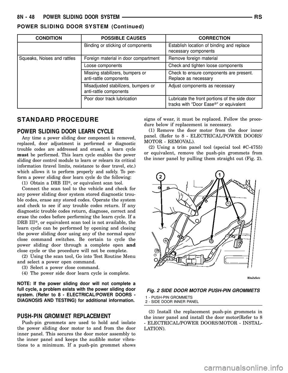
(2) Using a trim panel tool (special tool #C-4755)
or equivalent, remove the push-pin grommets from
the inner panel by pulling them straight out (Fig. 2).
(3) Install the replacement push-pin grommets in
the inner panel and install the door motor(Refer to 8
- ELECTRICAL/POWER DOORS/MOTOR - INSTAL-
LATION).
Fig. 2 SIDE DOOR MOTOR PUSH-PIN GROMMETS
1 - PUSH-PIN GROMMETS
2 - SIDE DOOR INNER PANEL
8N - 48 POWER SLIDING DOOR SYSTEMRS
POWER SLIDING DOOR SYSTEM (Continued)
Page 480 of 2339
LOWER DRIVE UNIT TRACK &
RACK
DESCRIPTION
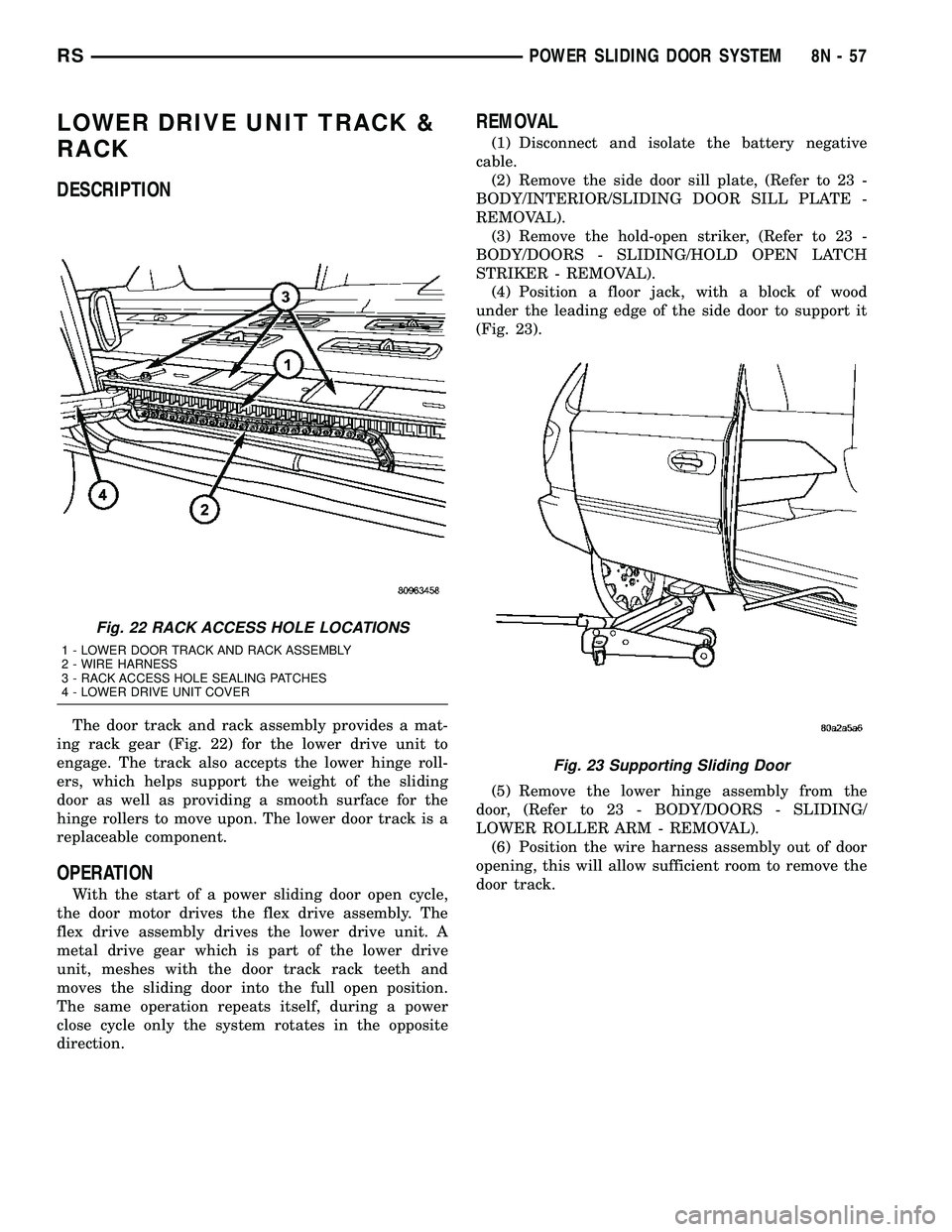
The door track and rack assembly provides a mat-
ing rack gear (Fig. 22) for the lower drive unit to
engage. The track also accepts the lower hinge roll-
ers, which helps support the weight of the sliding
door as well as providing a smooth surface for the
hinge rollers to move upon. The lower door track is a
replaceable component.
OPERATION
With the start of a power sliding door open cycle,
the door motor drives the flex drive assembly. The
flex drive assembly drives the lower drive unit. A
metal drive gear which is part of the lower drive
unit, meshes with the door track rack teeth and
moves the sliding door into the full open position.
The same operation repeats itself, during a power
close cycle only the system rotates in the opposite
direction.
REMOVAL
(1) Disconnect and isolate the battery negative
cable.
(2) Remove the side door sill plate, (Refer to 23 -
BODY/INTERIOR/SLIDING DOOR SILL PLATE -
REMOVAL).
(3) Remove the hold-open striker, (Refer to 23 -
BODY/DOORS - SLIDING/HOLD OPEN LATCH
STRIKER - REMOVAL).
(4) Position a floor jack, with a block of wood
under the leading edge of the side door to support it
(Fig. 23).
(5) Remove the lower hinge assembly from the
door, (Refer to 23 - BODY/DOORS - SLIDING/
LOWER ROLLER ARM - REMOVAL).
(6) Position the wire harness assembly out of door
opening, this will allow sufficient room to remove the
door track.
Fig. 22 RACK ACCESS HOLE LOCATIONS
1 - LOWER DOOR TRACK AND RACK ASSEMBLY
2 - WIRE HARNESS
3 - RACK ACCESS HOLE SEALING PATCHES
4 - LOWER DRIVE UNIT COVER
Fig. 23 Supporting Sliding Door
RSPOWER SLIDING DOOR SYSTEM8N-57
Page 490 of 2339
²Occupant Classification System- These
vehicles also include an Occupant Classification Sys-
tem (OCS) with components that are located on or in
the passenger front seat cushion. These components
include an Occupant Classification Module (OCM)
and a seat weight bladder and pressure sensor
assembly. In addition, this system includes a belt
tension sensor integral to the lower anchor of the
passenger side front seat belt. Vehicles equipped with
the OCS can be readily identified by a Passenger Air-
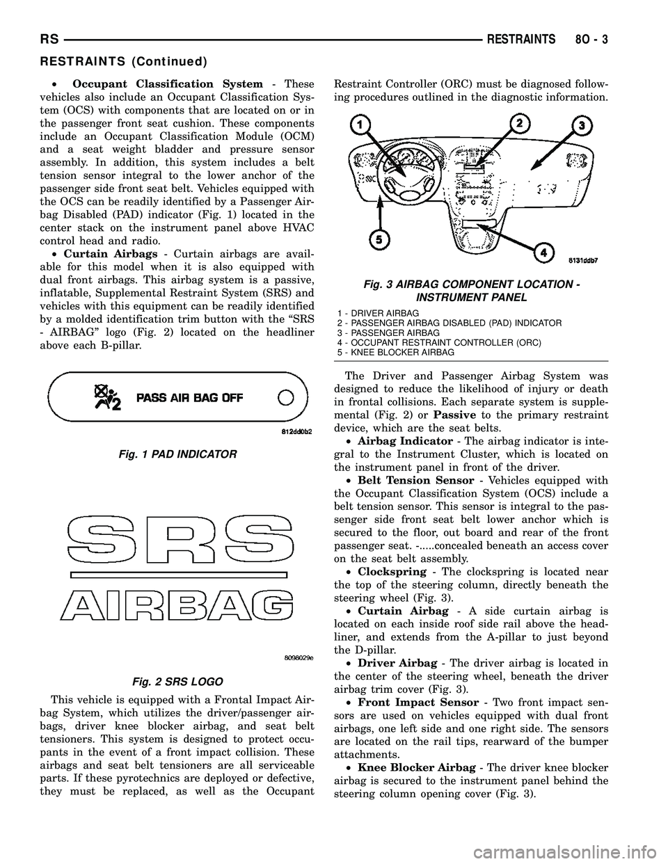
bag Disabled (PAD) indicator (Fig. 1) located in the
center stack on the instrument panel above HVAC
control head and radio.
²Curtain Airbags- Curtain airbags are avail-
able for this model when it is also equipped with
dual front airbags. This airbag system is a passive,
inflatable, Supplemental Restraint System (SRS) and
vehicles with this equipment can be readily identified
by a molded identification trim button with the ªSRS
- AIRBAGº logo (Fig. 2) located on the headliner
above each B-pillar.
This vehicle is equipped with a Frontal Impact Air-
bag System, which utilizes the driver/passenger air-
bags, driver knee blocker airbag, and seat belt
tensioners. This system is designed to protect occu-
pants in the event of a front impact collision. These
airbags and seat belt tensioners are all serviceable
parts. If these pyrotechnics are deployed or defective,
they must be replaced, as well as the OccupantRestraint Controller (ORC) must be diagnosed follow-
ing procedures outlined in the diagnostic information.
The Driver and Passenger Airbag System was
designed to reduce the likelihood of injury or death
in frontal collisions. Each separate system is supple-
mental (Fig. 2) orPassiveto the primary restraint
device, which are the seat belts.
²Airbag Indicator- The airbag indicator is inte-
gral to the Instrument Cluster, which is located on
the instrument panel in front of the driver.
²Belt Tension Sensor- Vehicles equipped with
the Occupant Classification System (OCS) include a
belt tension sensor. This sensor is integral to the pas-
senger side front seat belt lower anchor which is
secured to the floor, out board and rear of the front
passenger seat. -.....concealed beneath an access cover
on the seat belt assembly.
²Clockspring- The clockspring is located near
the top of the steering column, directly beneath the
steering wheel (Fig. 3).
²Curtain Airbag- A side curtain airbag is
located on each inside roof side rail above the head-
liner, and extends from the A-pillar to just beyond
the D-pillar.
²Driver Airbag- The driver airbag is located in
the center of the steering wheel, beneath the driver
airbag trim cover (Fig. 3).
²Front Impact Sensor- Two front impact sen-
sors are used on vehicles equipped with dual front
airbags, one left side and one right side. The sensors
are located on the rail tips, rearward of the bumper
attachments.
²Knee Blocker Airbag- The driver knee blocker
airbag is secured to the instrument panel behind the
steering column opening cover (Fig. 3).
Fig. 1 PAD INDICATOR
Fig. 2 SRS LOGO
Fig. 3 AIRBAG COMPONENT LOCATION -
INSTRUMENT PANEL
1 - DRIVER AIRBAG
2 - PASSENGER AIRBAG DISABLED (PAD) INDICATOR
3 - PASSENGER AIRBAG
4 - OCCUPANT RESTRAINT CONTROLLER (ORC)
5 - KNEE BLOCKER AIRBAG
RSRESTRAINTS8O-3
RESTRAINTS (Continued)
Page 496 of 2339
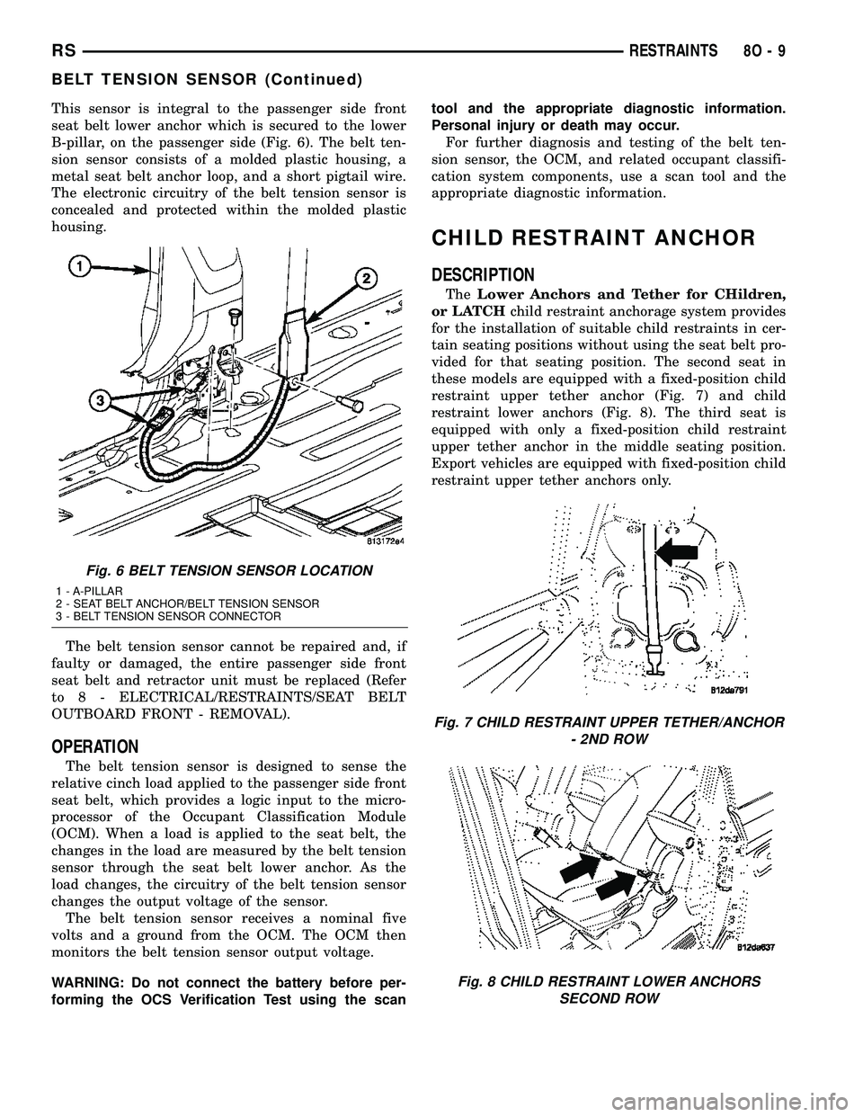
This sensor is integral to the passenger side front
seat belt lower anchor which is secured to the lower
B-pillar, on the passenger side (Fig. 6). The belt ten-
sion sensor consists of a molded plastic housing, a
metal seat belt anchor loop, and a short pigtail wire.
The electronic circuitry of the belt tension sensor is
concealed and protected within the molded plastic
housing.
The belt tension sensor cannot be repaired and, if
faulty or damaged, the entire passenger side front
seat belt and retractor unit must be replaced (Refer
to 8 - ELECTRICAL/RESTRAINTS/SEAT BELT
OUTBOARD FRONT - REMOVAL).
OPERATION
The belt tension sensor is designed to sense the
relative cinch load applied to the passenger side front
seat belt, which provides a logic input to the micro-
processor of the Occupant Classification Module
(OCM). When a load is applied to the seat belt, the
changes in the load are measured by the belt tension
sensor through the seat belt lower anchor. As the
load changes, the circuitry of the belt tension sensor
changes the output voltage of the sensor.
The belt tension sensor receives a nominal five
volts and a ground from the OCM. The OCM then
monitors the belt tension sensor output voltage.
WARNING: Do not connect the battery before per-
forming the OCS Verification Test using the scantool and the appropriate diagnostic information.
Personal injury or death may occur.
For further diagnosis and testing of the belt ten-
sion sensor, the OCM, and related occupant classifi-
cation system components, use a scan tool and the
appropriate diagnostic information.
CHILD RESTRAINT ANCHOR
DESCRIPTION
TheLower Anchors and Tether for CHildren,
or LATCHchild restraint anchorage system provides
for the installation of suitable child restraints in cer-
tain seating positions without using the seat belt pro-
vided for that seating position. The second seat in
these models are equipped with a fixed-position child
restraint upper tether anchor (Fig. 7) and child
restraint lower anchors (Fig. 8). The third seat is
equipped with only a fixed-position child restraint
upper tether anchor in the middle seating position.
Export vehicles are equipped with fixed-position child
restraint upper tether anchors only.
Fig. 6 BELT TENSION SENSOR LOCATION
1 - A-PILLAR
2 - SEAT BELT ANCHOR/BELT TENSION SENSOR
3 - BELT TENSION SENSOR CONNECTOR
Fig. 7 CHILD RESTRAINT UPPER TETHER/ANCHOR
- 2ND ROW
Fig. 8 CHILD RESTRAINT LOWER ANCHORS
SECOND ROW
RSRESTRAINTS8O-9
BELT TENSION SENSOR (Continued)
Page 501 of 2339
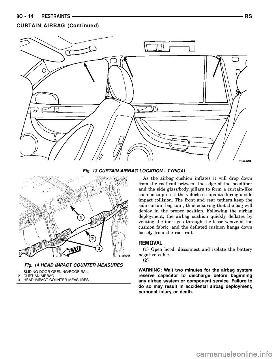
As the airbag cushion inflates it will drop down
from the roof rail between the edge of the headliner
and the side glass/body pillars to form a curtain-like
cushion to protect the vehicle occupants during a side
impact collision. The front and rear tethers keep the
side curtain bag taut, thus ensuring that the bag will
deploy in the proper position. Following the airbag
deployment, the airbag cushion quickly deflates by
venting the inert gas through the loose weave of the
cushion fabric, and the deflated cushion hangs down
loosely from the roof rail.
REMOVAL
(1) Open hood, disconnect and isolate the battery
negative cable.
(2)
WARNING: Wait two minutes for the airbag system
reserve capacitor to discharge before beginning
any airbag system or component service. Failure to
do so may result in accidental airbag deployment,
personal injury or death.
Fig. 13 CURTAIN AIRBAG LOCATION - TYPICAL
Fig. 14 HEAD IMPACT COUNTER MEASURES
1 - SLIDING DOOR OPENING/ROOF RAIL
2 - CURTIAN AIRBAG
3 - HEAD IMPACT COUNTER MEASURES
8O - 14 RESTRAINTSRS
CURTAIN AIRBAG (Continued)
Page 502 of 2339
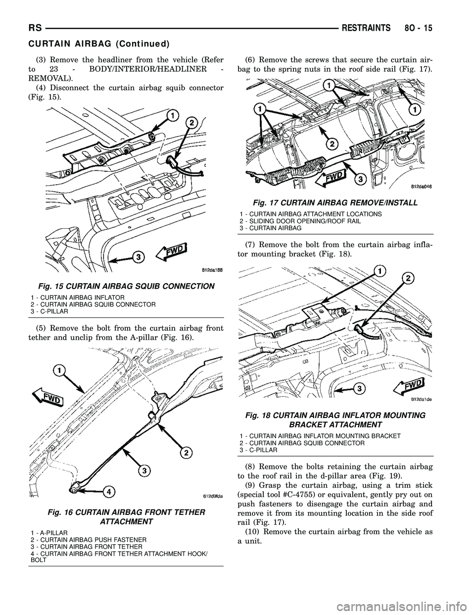
(3) Remove the headliner from the vehicle (Refer
to 23 - BODY/INTERIOR/HEADLINER -
REMOVAL).
(4) Disconnect the curtain airbag squib connector
(Fig. 15).
(5) Remove the bolt from the curtain airbag front
tether and unclip from the A-pillar (Fig. 16).(6) Remove the screws that secure the curtain air-
bag to the spring nuts in the roof side rail (Fig. 17).
(7) Remove the bolt from the curtain airbag infla-
tor mounting bracket (Fig. 18).
(8) Remove the bolts retaining the curtain airbag
to the roof rail in the d-pillar area (Fig. 19).
(9) Grasp the curtain airbag, using a trim stick
(special tool #C-4755) or equivalent, gently pry out on
push fasteners to disengage the curtain airbag and
remove it from its mounting location in the side roof
rail (Fig. 17).
(10) Remove the curtain airbag from the vehicle as
a unit.
Fig. 15 CURTAIN AIRBAG SQUIB CONNECTION
1 - CURTAIN AIRBAG INFLATOR
2 - CURTAIN AIRBAG SQUIB CONNECTOR
3 - C-PILLAR
Fig. 16 CURTAIN AIRBAG FRONT TETHER
ATTACHMENT
1 - A-PILLAR
2 - CURTAIN AIRBAG PUSH FASTENER
3 - CURTAIN AIRBAG FRONT TETHER
4 - CURTAIN AIRBAG FRONT TETHER ATTACHMENT HOOK/
BOLT
Fig. 17 CURTAIN AIRBAG REMOVE/INSTALL
1 - CURTAIN AIRBAG ATTACHMENT LOCATIONS
2 - SLIDING DOOR OPENING/ROOF RAIL
3 - CURTAIN AIRBAG
Fig. 18 CURTAIN AIRBAG INFLATOR MOUNTING
BRACKET ATTACHMENT
1 - CURTAIN AIRBAG INFLATOR MOUNTING BRACKET
2 - CURTAIN AIRBAG SQUIB CONNECTOR
3 - C-PILLAR
RSRESTRAINTS8O-15
CURTAIN AIRBAG (Continued)
Page 503 of 2339
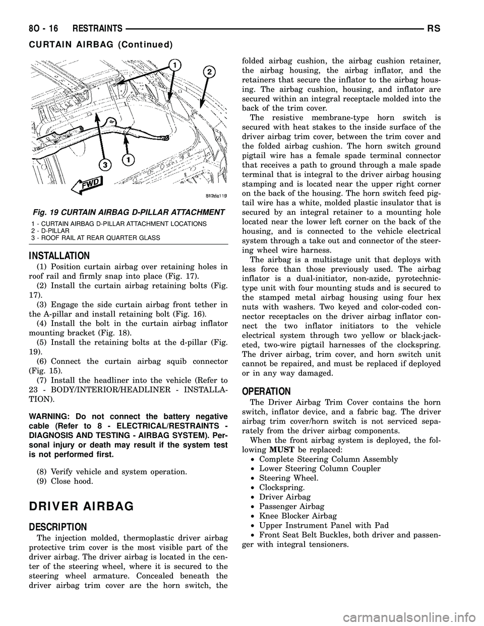
INSTALLATION
(1) Position curtain airbag over retaining holes in
roof rail and firmly snap into place (Fig. 17).
(2) Install the curtain airbag retaining bolts (Fig.
17).
(3) Engage the side curtain airbag front tether in
the A-pillar and install retaining bolt (Fig. 16).
(4) Install the bolt in the curtain airbag inflator
mounting bracket (Fig. 18).
(5) Install the retaining bolts at the d-pillar (Fig.
19).
(6) Connect the curtain airbag squib connector
(Fig. 15).
(7) Install the headliner into the vehicle (Refer to
23 - BODY/INTERIOR/HEADLINER - INSTALLA-
TION).
WARNING: Do not connect the battery negative
cable (Refer to 8 - ELECTRICAL/RESTRAINTS -
DIAGNOSIS AND TESTING - AIRBAG SYSTEM). Per-
sonal injury or death may result if the system test
is not performed first.
(8) Verify vehicle and system operation.
(9) Close hood.
DRIVER AIRBAG
DESCRIPTION
The injection molded, thermoplastic driver airbag
protective trim cover is the most visible part of the
driver airbag. The driver airbag is located in the cen-
ter of the steering wheel, where it is secured to the
steering wheel armature. Concealed beneath the
driver airbag trim cover are the horn switch, thefolded airbag cushion, the airbag cushion retainer,
the airbag housing, the airbag inflator, and the
retainers that secure the inflator to the airbag hous-
ing. The airbag cushion, housing, and inflator are
secured within an integral receptacle molded into the
back of the trim cover.
The resistive membrane-type horn switch is
secured with heat stakes to the inside surface of the
driver airbag trim cover, between the trim cover and
the folded airbag cushion. The horn switch ground
pigtail wire has a female spade terminal connector
that receives a path to ground through a male spade
terminal that is integral to the driver airbag housing
stamping and is located near the upper right corner
on the back of the housing. The horn switch feed pig-
tail wire has a white, molded plastic insulator that is
secured by an integral retainer to a mounting hole
located near the lower left corner on the back of the
housing, and is connected to the vehicle electrical
system through a take out and connector of the steer-
ing wheel wire harness.
The airbag is a multistage unit that deploys with
less force than those previously used. The airbag
inflator is a dual-initiator, non-azide, pyrotechnic-
type unit with four mounting studs and is secured to
the stamped metal airbag housing using four hex
nuts with washers. Two keyed and color-coded con-
nector receptacles on the driver airbag inflator con-
nect the two inflator initiators to the vehicle
electrical system through two yellow or black-jack-
eted, two-wire pigtail harnesses of the clockspring.
The driver airbag, trim cover, and horn switch unit
cannot be repaired, and must be replaced if deployed
or in any way damaged.
OPERATION
The Driver Airbag Trim Cover contains the horn
switch, inflator device, and a fabric bag. The driver
airbag trim cover/horn switch is not serviced sepa-
rately from the driver airbag components.
When the front airbag system is deployed, the fol-
lowingMUSTbe replaced:
²Complete Steering Column Assembly
²Lower Steering Column Coupler
²Steering Wheel.
²Clockspring.
²Driver Airbag
²Passenger Airbag
²Knee Blocker Airbag
²Upper Instrument Panel with Pad
²Front Seat Belt Buckles, both driver and passen-
ger with integral tensioners.
Fig. 19 CURTAIN AIRBAG D-PILLAR ATTACHMENT
1 - CURTAIN AIRBAG D-PILLAR ATTACHMENT LOCATIONS
2 - D-PILLAR
3 - ROOF RAIL AT REAR QUARTER GLASS
8O - 16 RESTRAINTSRS
CURTAIN AIRBAG (Continued)
Page 506 of 2339
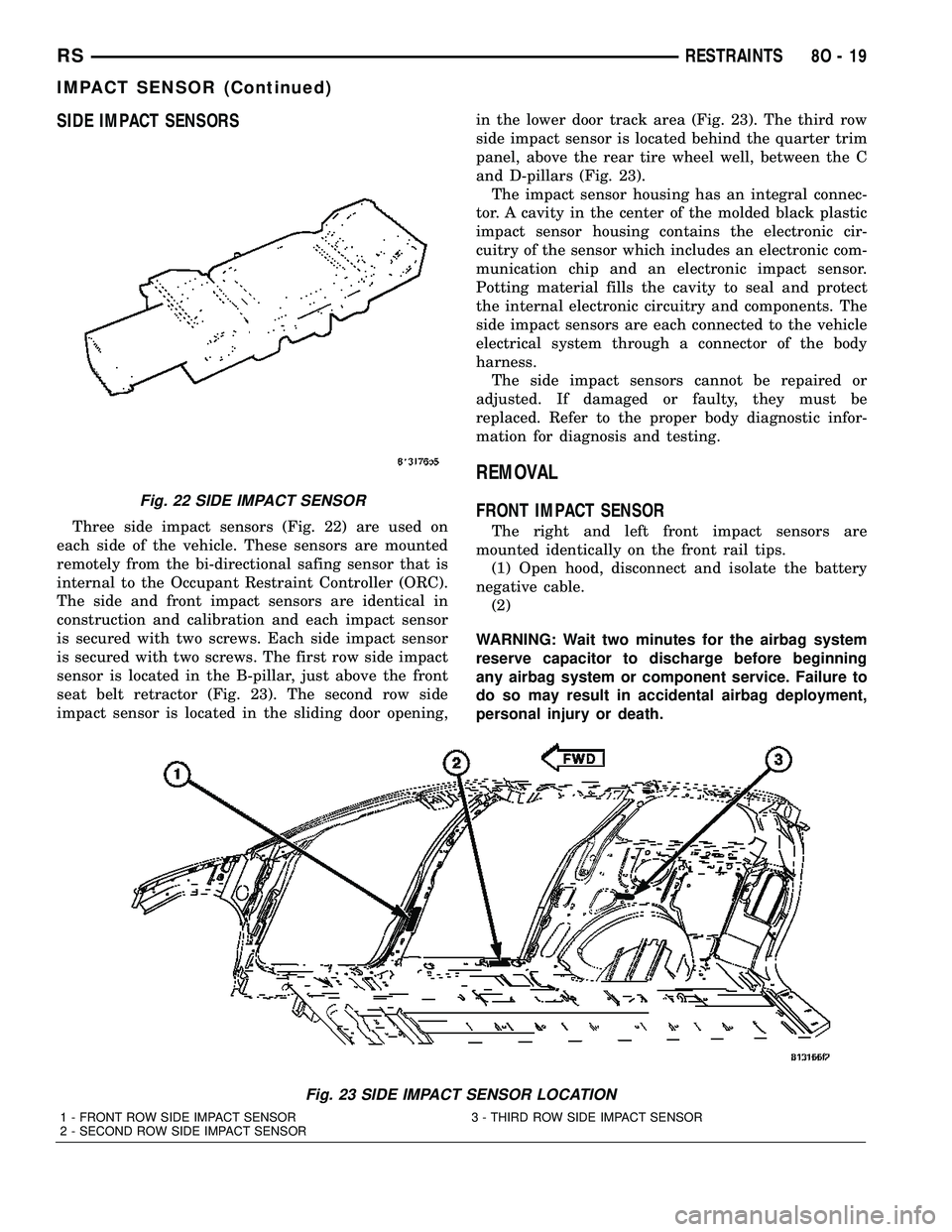
SIDE IMPACT SENSORS
Three side impact sensors (Fig. 22) are used on
each side of the vehicle. These sensors are mounted
remotely from the bi-directional safing sensor that is
internal to the Occupant Restraint Controller (ORC).
The side and front impact sensors are identical in
construction and calibration and each impact sensor
is secured with two screws. Each side impact sensor
is secured with two screws. The first row side impact
sensor is located in the B-pillar, just above the front
seat belt retractor (Fig. 23). The second row side
impact sensor is located in the sliding door opening,in the lower door track area (Fig. 23). The third row
side impact sensor is located behind the quarter trim
panel, above the rear tire wheel well, between the C
and D-pillars (Fig. 23).
The impact sensor housing has an integral connec-
tor. A cavity in the center of the molded black plastic
impact sensor housing contains the electronic cir-
cuitry of the sensor which includes an electronic com-
munication chip and an electronic impact sensor.
Potting material fills the cavity to seal and protect
the internal electronic circuitry and components. The
side impact sensors are each connected to the vehicle
electrical system through a connector of the body
harness.
The side impact sensors cannot be repaired or
adjusted. If damaged or faulty, they must be
replaced. Refer to the proper body diagnostic infor-
mation for diagnosis and testing.
REMOVAL
FRONT IMPACT SENSOR
The right and left front impact sensors are
mounted identically on the front rail tips.
(1) Open hood, disconnect and isolate the battery
negative cable.
(2)
WARNING: Wait two minutes for the airbag system
reserve capacitor to discharge before beginning
any airbag system or component service. Failure to
do so may result in accidental airbag deployment,
personal injury or death.
Fig. 23 SIDE IMPACT SENSOR LOCATION
1 - FRONT ROW SIDE IMPACT SENSOR 3 - THIRD ROW SIDE IMPACT SENSOR
2 - SECOND ROW SIDE IMPACT SENSOR
Fig. 22 SIDE IMPACT SENSOR
RSRESTRAINTS8O-19
IMPACT SENSOR (Continued)
Page 510 of 2339
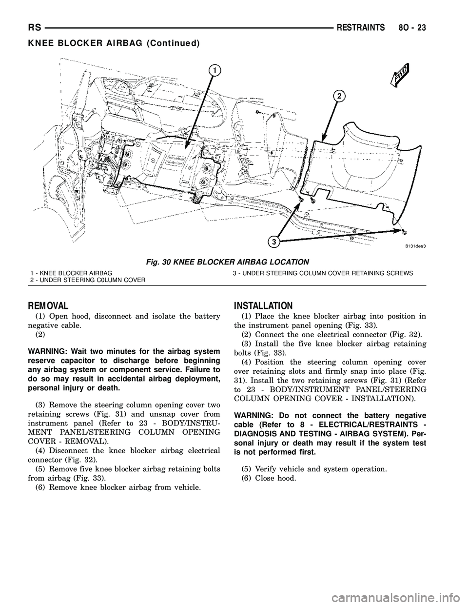
REMOVAL
(1) Open hood, disconnect and isolate the battery
negative cable.
(2)
WARNING: Wait two minutes for the airbag system
reserve capacitor to discharge before beginning
any airbag system or component service. Failure to
do so may result in accidental airbag deployment,
personal injury or death.
(3) Remove the steering column opening cover two
retaining screws (Fig. 31) and unsnap cover from
instrument panel (Refer to 23 - BODY/INSTRU-
MENT PANEL/STEERING COLUMN OPENING
COVER - REMOVAL).
(4) Disconnect the knee blocker airbag electrical
connector (Fig. 32).
(5) Remove five knee blocker airbag retaining bolts
from airbag (Fig. 33).
(6) Remove knee blocker airbag from vehicle.
INSTALLATION
(1) Place the knee blocker airbag into position in
the instrument panel opening (Fig. 33).
(2) Connect the one electrical connector (Fig. 32).
(3) Install the five knee blocker airbag retaining
bolts (Fig. 33).
(4) Position the steering column opening cover
over retaining slots and firmly snap into place (Fig.
31). Install the two retaining screws (Fig. 31) (Refer
to 23 - BODY/INSTRUMENT PANEL/STEERING
COLUMN OPENING COVER - INSTALLATION).
WARNING: Do not connect the battery negative
cable (Refer to 8 - ELECTRICAL/RESTRAINTS -
DIAGNOSIS AND TESTING - AIRBAG SYSTEM). Per-
sonal injury or death may result if the system test
is not performed first.
(5) Verify vehicle and system operation.
(6) Close hood.
Fig. 30 KNEE BLOCKER AIRBAG LOCATION
1 - KNEE BLOCKER AIRBAG 3 - UNDER STEERING COLUMN COVER RETAINING SCREWS
2 - UNDER STEERING C0LUMN COVER
RSRESTRAINTS8O-23
KNEE BLOCKER AIRBAG (Continued)
Page 512 of 2339
OCCUPANT CLASSIFICATION
MODULE
DESCRIPTION
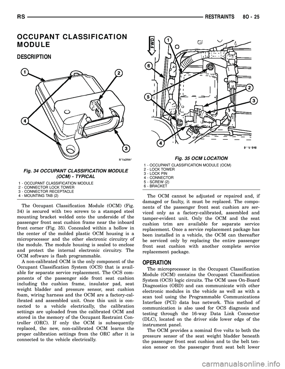
The Occupant Classification Module (OCM) (Fig.
34) is secured with two screws to a stamped steel
mounting bracket welded onto the underside of the
passenger front seat cushion frame near the inboard
front corner (Fig. 35). Concealed within a hollow in
the center of the molded plastic OCM housing is a
microprocessor and the other electronic circuitry of
the module. The module housing is sealed to enclose
and protect the internal electronic circuitry. The
OCM software is flash programmable.
A non-calibrated OCM is the only component of the
Occupant Classification System (OCS) that is avail-
able for separate service replacement. The OCS com-
ponents of the passenger side front seat cushion
including the cushion frame, insulator pad, seat
weight bladder and pressure sensor, seat cushion
foam, wiring harness and the OCM are a factory-cal-
ibrated and assembled unit. Once this unit is con-
nected to a vehicle electrically, the calibration
settings are uploaded from the calibrated OCM and
stored in the memory of the Occupant Restraint Con-
troller (ORC). If only the OCM is subsequently
replaced, the new, non-calibrated OCM learns the
proper calibration settings from the ORC after it is
connected to the vehicle electrically.The OCM cannot be adjusted or repaired and, if
damaged or faulty, it must be replaced. The compo-
nents of the passenger front seat cushion are ser-
viced only as a factory-calibrated, assembled and
tamper-evident unit. Only the OCM and the seat
cushion trim are available for separate service
replacement. Once a service replacement package has
been installed in a vehicle, the OCM can thereafter
be serviced only by replacing the entire passenger
front seat cushion with another complete service
replacement package.
OPERATION
The microprocessor in the Occupant Classification
Module (OCM) contains the Occupant Classification
System (OCS) logic circuits. The OCM uses On-Board
Diagnostics (OBD) and can communicate with other
electronic modules in the vehicle as well as with a
scan tool using the Programmable Communications
Interface (PCI) data bus network. This method of
communication is also used for OCS diagnosis and
testing through the 16-way Data Link Connector
(DLC), located on the driver side lower edge of the
instrument panel.
The OCM provides a nominal five volts to both the
pressure sensor of the seat weight bladder beneath
the passenger front seat cushion and to the belt ten-
sion sensor on the passenger front seat belt lower
Fig. 34 OCCUPANT CLASSIFICATION MODULE
(OCM) - TYPICAL
1 - OCCUPANT CLASSIFICATION MODULE
2 - CONNECTOR LOCK TOWER
3 - CONNECTOR RECEPTACLE
4 - MOUNTING TAB (2)
Fig. 35 OCM LOCATION
1 - OCCUPANT CLASSIFICATION MODULE (OCM)
2 - LOCK TOWER
3 - LOCK PIN
4 - CONNECTOR
5 - SCREW (2)
6 - BRACKET
RSRESTRAINTS8O-25